HHV20011107Emergency Portable Cellular Telephone
Panasonic Electric Works Co., Ltd.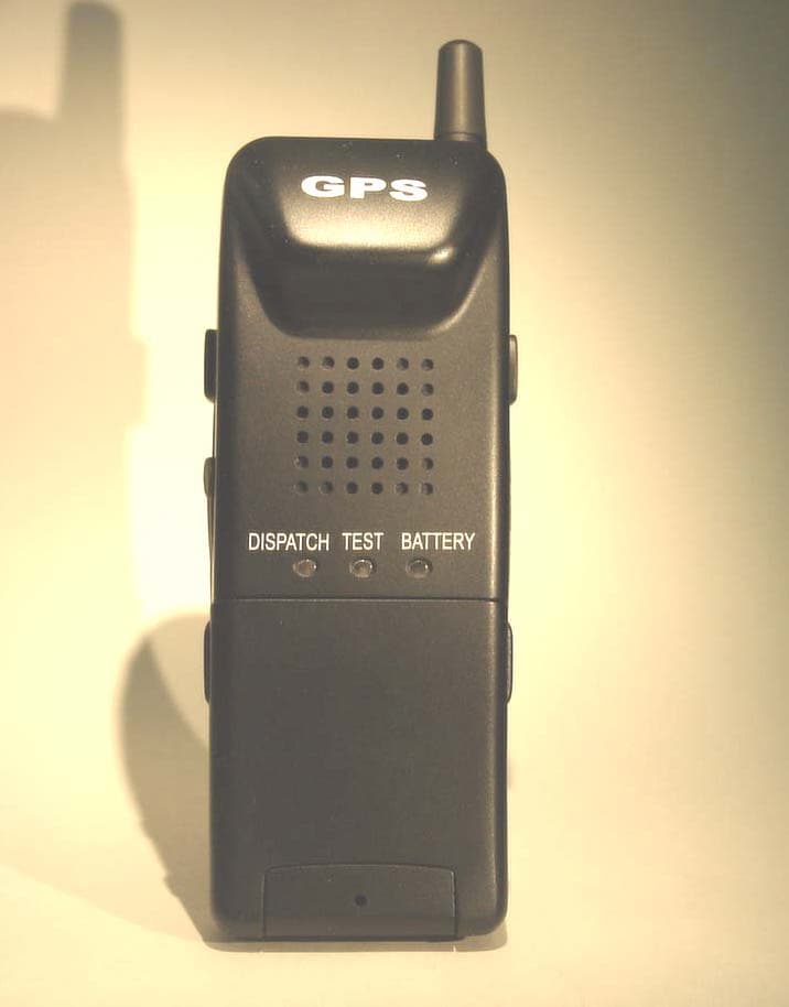
Click to zoom
Application Details
- Equipment Class
- TNT - Licensed Non-Broadcast Transmitter Worn on Body
- Date of Grant
- May 30, 2002
- Application Purpose
- Original Equipment
- Date of Application
- Feb 04, 2002
- Equipment Note
- Emergency Portable Cellular Telephone
- Frequency Range
- 824.04000000 - 848.97000000
- Country
- Japan
Documents & Files
Document Text
Text extracted from the exhibit documents filed with the FCC. Open a document above to read the original.
Cover Letter(s)
Applicant : Matsushita Electric Works, Ltd. Transmitter Type : HHV20011107 LIST OF EXHIBITS EXHIBIT NO. DESCRIPTION 1 Grantee’s Certification 2 Test Data Certification (2 Pages) 3 Descriptive Information (15Pages) 4 Technical Description (2 Pages) 5 FCC Label 6 Photograph: Front View (2 Page) 7 Photograph: Back View (3 Page) 8 Photograph: Closs shot View 9 Photograph: Top View 10 Photograph: Bottom View 11 Photograph: Right Side View 12 Photograph: Left Side View 13 Photograph: Front View of PC Board (2 Page) 14 Photograph: Back View of PC Board (2 Page ) 15 Block Diagram of Cellular Telephone Transmitter 16 Schematic Diagram of Transceiver 17 Block Diagram TCXO System 18 Schematic Diagram of VCXO 19 Schematic Diagram of TX VCO 20 Operating Instructions (11 Pages) PAGE 1 OF 2 Applicant : Matsushita Electric Works, Ltd. Transmitter Type : HHV20011107 LIST OF EXHIBITS ( Continued ) EXHIBIT NO. DESCRIPTION 21 Tune-Up Procedure (7 Pages) 22 Data: Report of Measurement (KEC) (16 Pages) 23 Graph: SAT Filter Response 24 Graph: ST and Wide Band Data Filter Response 25 Graph: Post-Limiter Filter Response 26 Graph: Transmit Audio Frequency Response (2 Pages) 27 Graph: Modulation Limiting 28 Graph: Occupied Bandwidth (No Modulation) 29 Graph: Occupied Bandwidth (Audio) 30 Graph: Occupied Bandwidth (SAT) 31 Graph: Occupied Bandwidth (Audio Plus SAT) 32 Graph: Occupied Bandwidth (DTMF plus SAT) 33 Graph: Occupied Bandwidth (WBD) (2 Pages) 34 Graph: Occupied Bandwidth (ST) 35 Graph: Occupied Bandwidth (SAT Plus ST) 36 Graph: Transmitter Conducted Spurious Emissions (5 pages) 37 Graph: Transmitter Conducted Spurious Emissions (Receive Band, 3 pages) 38 Graph: Frequency Stability-Temperature Variation 39 Graph: Frequency Stability-Voltage Variation 40 Data: Report of Measurements (16 Pages) (Intertek Testing Services NA, Inc. Laboratory) PAGE 2 OF 2
Cover Letter(s)
Date:April /2 /2002 To:Mr.Diane Poole, FCC Application Processing Branch From:Iwao Oyaizu, Matsushita Electric Works,Ltd Re: FCC ID HHV20011107 Applicant: Matsushita Electric Works Ltd Correspondence Reference Number: 22428 Form731 Confirmation Number: EA829170 >EMC >Please draw the emission mask for some of the >Bandwidth Plot. Reply: Mask is added to each Bandwidth Plot of EXHIBIT 28 to 36 and it is uploaded. >SAR >1. Following statement from users manual has some >grammar errors. Please see example body-worn >statements in Suppl C and revise accordingly. >This device was tested for typical body-worn >operations using the belt-clip supplied with the >product. >The use of other belt-clip and other non-accessories >may not comply with FCC RF exposure requirements >and should be void. Reply to item 1: Correction has been made to EXHIBIT20 Operating Instructions and it is uploaded. >2. Because device is shaped like a phone, even with >users manual instructions people may use it next it >to the head, in which case compliance with SAR limits >should be evaluated. Please justify. The best way >to prevent head use is a caution label on device. Applicant : Matsushita Electric Works, Ltd. Transmitter Type : HHV20011107 EXHIBIT 41 PAGE 1 OF 5 Reply to Item 2: Caution label of the following photo is attached. Also, caution label is uploaded.. >3. df 1 correct ? Reply to Item 3: The following reply was received from SAR laboratory During the SAR test, the phone was transmitting a CW (continuous wave) signal (in test mode). Therefore, we setup in the SAR System the Crest Factor = 1 which is equivalent to the Duty Factor of 1" >4. Form 731 power is 600mW ERP. EMC shows 619mW. >SAR conducted power is 486mW. Tuneup procedure shows >446mW. Please clarify what power is requested. Please >use same power level in all tests as necessary. What >is conducted power in EMC compared to SAR? Reply to item 4: EUT which was used for each measurement is identical. The current application details are shown in TABLE 1. Applicant : Matsushita Electric Works, Ltd. Transmitter Type : HHV20011107 EXHIBIT 41 PAGE 2 OF 5 Item which is not harmonized is Tune-up Procedure and Form731. We will change Form731 as per TABLE2 to harmonize it. This letter gives authorization to change the Rated RF Power Output from 0.6W to 0.619W on the Form 731 TABLE 1 FrequencyERP 2.1046(a)Conducted 2.1046(a) Body SAR @ Conducted Power TUNE-UP ProcedureFORM731 991ch/824.04MHz 0.619W / 27.92dBm0.486W / 26.87dBm 1.41 W/kg @ 26.87dBm(0.486W) 383ch/836.49MHz 0.586W / 27.68dBm0.449W / 26.52dBm 1.45 W/kg @ 26.52dBm(0.449W) 0.447W / 26.5dBm0.6W ERP 799ch/848.97MHz 0.594W / 27.74dBm0.379W / 25.79dBm 1.39 W/kg @ 25.79dBm(0.379W) TABLE 2 FrequencyERP 2.1046(a)Conducted 2.1046(a) Body SAR @ Conducted Power TUNE-UP ProcedureFORM731 991ch/824.04MHz 0.619W / 27.92dBm 0.486W / 26.87dBm 1.41 W/kg @ 26.87dBm(0.486W) 383ch/836.49MHz 0.586W / 27.68dBm0.449W / 26.52dBm 1.45 W/kg @ 26.52dBm(0.449W) 0.447W / 26.5dBm 0.619W ERP 799ch/848.97MHz 0.594W / 27.74dBm0.379W / 25.79dBm 1.39 W/kg @ 25.79dBm(0.379W) >5. SAR report pg 8/38 shows blisters or debris on >phantom. Are same blisters in test area of phantom? >9. SAR report pages 8,9 appear to show 2 different >phantoms. Why? Was same liquid use in both phantoms. Reply to items 5&9: The following reply was received from SAR laboratory "5 & 9. Our phantom does not have blisters. There was a little remains of a tape producing light reflections. We cleaned the phantom, and you can see the bottom of the phantom on the attached photos. We have only one phantom. Applicant : Matsushita Electric Works, Ltd. Transmitter Type : HHV20011107 EXHIBIT 41 PAGE 3 OF 5 >6. Please justify duty cycle = 1. Reply to item 6: The following reply was received from SAR laboratory 6. The phone was tested in CW mode, so we used the Crest Factor of 1. >7. FYI - direct contact SAR does not exactly simulate >hand condition, because antenna loading will usually >be different with hand. Thank you for your advice. >8. 900 MHz head probe factor incorrectly used for 835 >MHz body test. Please adjust or re-test all SAR values >and plots. Reply to item 8: The following reply was received from SAR laboratory 8. At the time when we performed the test we had a probe calibrated for head tissue only. Later we asked SPIAG to perform the calibration for muscle tissue. The conversion Factor for muscle is slightly less (5.72 instead of 5.83). Please see attached plot recalculated for the Conversion Factor of 5.72 (in worse case, 836 MHz). The SAR reading increased from 1.42 mW/g to 1.45 mW/g. Revision has been made to EXHIBIT40 SAR Report of Measurements and it is uploaded. Applicant : Matsushita Electric Works, Ltd. Transmitter Type : HHV20011107 EXHIBIT 41 PAGE 4 OF 5 >10. Some SAR plots show different liquid parameters. >Please explain and correct as necessary. Reply to item 10: The following reply was received from SAR laboratory 10. We used different liquid parameters for different frequencies: 824 MHz (epsilon=56.2, sigma=0.92), 836 MHz (epsilon=55.2, sigma=0.97), 849 MHz (epsilon=55.4, sigma=0.97). These numbers are what we measured." >11. Operational desc. shows 26.5 dBm +2 dB = 708mW is >possible. Please explain, or reduce power, also >considering question 4 above. Tune-up shows 26.5 + >0 dB. Please harmonize power across all parts of >filing. Reply to item 11: Revision has been made to Page 1 of 15 of EXHIBIT 3 Descriptive Information and it is uploaded. Sincerely, Iwao Oyaizu Matsushita Electric Works,Ltd Applicant : Matsushita Electric Works, Ltd. Transmitter Type : HHV20011107 EXHIBIT 41 PAGE 5 OF 5
Cover Letter(s)
Applicant : Matsushita Electric Works, Ltd. Transmitter : HHV20011107 Date: May,16,2002 To:Mr.Diane Pool, FCC Application Processing Branch. From:Iwao Oyaizu, Matsushita Electric Works,LTD. Re: FCC ID HHV20011107 Applicant: Matsushita Electric Works, Ltd Correspondence Reference Number: 22726 Form 731 Confirmation Number: EA829170 >1. Users manual has been changed, but again please >consider using the suggested text from Suppl. C: > >"For body worn operation, this phone has been tested >and meets the FCC RF exposure guidelines when used with >the (manufacturer name) accessories supplied or >designated for this product. Use of other accessories >may not ensure compliance with FCC RF exposure guidelines." Reply to Item 1: Revised page 2 of Operating Instructions (EXHIBIT 20) is uploaded . >2. "Caution label" looks like a package insert. Please >consider to use a stick-on label on the exterior of the >device. If used, please submit photos of label placement >on device. EXHIBIT 43 PAGE 1 OF 3 Applicant : Matsushita Electric Works, Ltd. Transmitter : HHV20011107 Reply to Item 2: The caution label will be inserted (see EXHIBIT 42) so that the user see it when taking the device from the package. Considering the following points, this seems enough way to avoid the situation which the user uses it near his ear like a conventional portable cellular telephone. (1) The user has the special contract with the service provider for emergency call service, and the device has not any conventional keypad for dialing. There would be few chance for other person to uses it. (2) The device has no ear receiver usually used for handset. The devise has a loudspeaker and a high sensitive microphone to enable the user to hear and speak at 10 feet away from the device. Since the device has not any volume control for loudspeaker, the user actually cannot hold it near his ear in a phone call because of its loud sound from the loudspeaker. Caution label of the following photo is attached. Also, Revised caution label is uploaded.. EXHIBIT 43 PAGE 2 OF 3 Applicant : Matsushita Electric Works, Ltd. Transmitter : HHV20011107 >3. For Part 22 amps mode when the ERP is greater than >600 mW, we list 600 mW but the SAR must be tested at >maximum ERP (target output power + any listed tolerance). >We place a note in the remarks field that indicates this >ERP and state that the device cannot exceed this level. We noted your comment. Sincerely, Iwao Oyaizu Matsushita Electric Works, Ltd. EXHIBIT 43 PAGE 3 OF 3
Cover Letter(s)
May 24, 2002 Federal Communications Commission Authorization and Evaluation Division 7435 Oakland Mills Road Columbia, MD 21046 Attention : Equipment Authorization Branch Request for Confidentiality Pursuant to Sections 0.457 (d) (l) (ii) and 0.459 of the Commission’s Rules, the Applicant hereby requests confidential treatment of some of the information accompanying this Application of FCC ID: HHV20011107. Since these materials contain trade secrets and proprietary information not customarily released to the public and the public disclosure of these matters might be harmful to the Applicant and provide unjustified benefits to its competitors, the Applicant request the following listed exhibits be held as confidential and withheld from the Public Information File. - Exhibit Type : Operational Description - Exhibit Type : Parts List / Tune Up Info - Exhibit Type : Block Diagram - Exhibit Type : Schematics - Exhibit Type : Internal Photos - Exhibit Type : Users Manual EXHIBIT 44 PAGE 1 OF 1
Cover Letter(s)
May 25, 2002 Federal Communications Commission Authorization and Evaluation Division 7435 Oakland Mills Road Columbia, MD 21046 Attention : Equipment Authorization Branch Request for Confidentiality Pursuant to Sections 0.457 (d) (l) (ii) and 0.459 of the Commission’s Rules, the Applicant hereby requests confidential treatment of some of the information accompanying this Application of FCC ID: HHV20011107. Since these materials contain trade secrets and proprietary information not customarily released to the public and the public disclosure of these matters might be harmful to the Applicant and provide unjustified benefits to its competitors, the Applicant request the following listed exhibits be held as confidential and withheld from the Public Information File. - Exhibit Type : Operational Description - Exhibit Type : Parts List / Tune Up Info - Exhibit Type : Block Diagram - Exhibit Type : Schematics EXHIBIT 45 PAGE 1 OF 1
External Photos
Applicant : Matsushita Electric Works, Ltd. Transmitter Type : HHV20011107 EXHIBIT 6 Front View PAGE 1 OF 2 Applicant : Matsushita Electric Works, Ltd. Transmitter Type : HHV20011107 EXHIBIT 6 Front View PAGE 2 OF 2
External Photos
Applicant : Matsushita Electric Works, Ltd. Transmitter Type : HHV20011107 EXHIBIT 7 Back View PAGE 1 OF 3 Applicant : Matsushita Electric Works, Ltd. Transmitter Type : HHV20011107 EXHIBIT 7 Back View PAGE 2 OF 3 Applicant : Matsushita Electric Works, Ltd. Transmitter Type : HHV20011107 EXHIBIT 7 Back View PAGE 3 OF 3
External Photos
Applicant : Matsushita Electric Works, Ltd. Transmitter Type : HHV20011107 EXHIBIT 8 Closs shot View
External Photos
Applicant : Matsushita Electric Works, Ltd. Transmitter Type : HHV20011107 EXHIBIT 9 Top View
External Photos
Applicant : Matsushita Electric Works, Ltd. Transmitter Type : HHV20011107 EXHIBIT 10 Bottom View
External Photos
Applicant : Matsushita Electric Works, Ltd. Transmitter Type : HHV20011107 EXHIBIT 11 Right Side View
External Photos
Applicant : Matsushita Electric Works, Ltd. Transmitter Type : HHV20011107 EXHIBIT 12 Left Side View
ID Label/Location Info
28A4xxxx MADE IN JAPAN FCC ID: HHV20011107 Applicant: Matsushita Electric Works, Ltd.Transmitter Type: HHV20011107 EXHIBIT 5
RF Exposure Info
1365 Adams Court, Menlo Park, CA 94025 Matsushita Electric Works, Ltd, Model No: PSD Date of Test: January 7 & 11, 2002 FCC ID: HHV20011107 File: 30171762Page 1 of 38RSS-102 & FCC Part 2 SAR Evaluation TABLE OF CONTENTS 1.0JOB DESCRIPTION................................................................................................................2 1.1Client Information..........................................................................................................2 1.2Equipment under test (EUT)...........................................................................................2 1.3Test Plan Reference........................................................................................................2 1.4System Test Configuration.............................................................................................3 1.4.1System Block Diagram & Support equipment....................................................3 1.4.2Test Position......................................................................................................4 1.4.3Test Condition...................................................................................................6 1.5 Modifications required for compliance.............................................................................6 1.6Additions, deviations and exclusions from standards.......................................................6 2.0SAR EVALUATION.................................................................................................................7 2.1SAR Limits.....................................................................................................................7 2.2Configuration Photographs.............................................................................................8 2.3System Verification......................................................................................................14 2.4Evaluation Procedures..................................................................................................14 2.5Test Results..................................................................................................................15 3.0TEST EQUIPMENT...............................................................................................................17 3.1Equipment List.............................................................................................................17 3.2Muscle Tissue Simulating Liquid..................................................................................18 3.3E-Field Probe Calibration.............................................................................................18 3.4Measurement Uncertainty.............................................................................................19 3.5Measurement Tractability.............................................................................................19 4.0WARNING LABEL INFORMATION - USA........................................................................20 5.0REFERENCES.......................................................................................................................21 6.0DOCUMENT HISTORY........................................................................................................22 APPENDIX A - SAR Evaluation Data................................................................................................23 APPENDIX B - E-Field Probe Calibration Data................................................................................30 1365 Adams Court, Menlo Park, CA 94025 Matsushita Electric Works, Ltd, Model No: PSD Date of Test: January 7 & 11, 2002 FCC ID: HHV20011107 File: 30171762Page 2 of 38RSS-102 & FCC Part 2 SAR Evaluation 1.0JOB DESCRIPTION 1.1 Client Information The PSD has been tested at the request of: Company:Matsushita Electric Works, Ltd 1048, Kadoma Osaka, 571-8686 Japan Name of contact:Mr. Akira Ohya Telephone:+81-6-6906-0473 Fax:+81-6-6906-0520 1.2 Equipment under test (EUT) Product Descriptions: Equipment Emergency Portable Cellular Telephone Trade NameMatsushita Electric Works, Ltd. P/N. PSD FCC ID HHV20011107 S/N No.17407801777 Category Portable RF ExposureUncontrolled Environment Frequency Band824-849 MHzSystemAMPS EUT Antenna Description TypeMonopoleConfigurationFixed Dimensions17.4mm (L),Gain2.14 dBi LocationRight side top Use of Product:Emergency calls. Manufacturer:Shintom Co., Ltd. Production is planned:[X ] Yes, [ ] No EUT receive date:January 3, 2002 EUT received condition:Good working condition prototype Test start date:January 3, 2002 Test end date:January 11, 2002 1.3 Test Plan Reference FCC rule part 2.1093, FCC Docket 96-326 & Supplement C (Edition 01 - 01) to OET Bulletin 65 1365 Adams Court, Menlo Park, CA 94025 Matsushita Electric Works, Ltd, Model No: PSD Date of Test: January 7 & 11, 2002 FCC ID: HHV20011107 File: 30171762Page 3 of 38RSS-102 & FCC Part 2 SAR Evaluation 1.4 System Test Configuration 1.4.1 System Block Diagram & Support equipment The diagram shown below details test configuration of the equipment under test. No Support Equipment was used. The test sample was operated in a test mode that allows control of the transmitter without the need to place actual phone calls. For the purposes of this test the device is commanded to test mode and manually set to the proper channel, transmitter power level and transmit mode of operation. The device was then placed in the SAR measurement system with a fully charged battery. EUT 1365 Adams Court, Menlo Park, CA 94025 Matsushita Electric Works, Ltd, Model No: PSD Date of Test: January 7 & 11, 2002 FCC ID: HHV20011107 File: 30171762Page 4 of 38RSS-102 & FCC Part 2 SAR Evaluation 1.4.2Test Position Three test configurations were used to show compliance with the FCC RF human exposure requirements. In all configurations, the PSD was configured for testing in a typical fashion (as a customer would normally use it). Due to the appli…
Text truncated - open the document above for the full version.
RF Exposure Info
1365 Adams Court, Menlo Park, CA 94025 Matsushita Electric Works, Ltd, Model No: PSD Date of Test: January 7 & 11, 2002 FCC ID: HHV20011107 File: 30171762aPage 1 of 38RSS-102 & FCC Part 2 SAR Evaluation TABLE OF CONTENTS 1.0JOB DESCRIPTION................................................................................................................2 1.1Client Information..........................................................................................................2 1.2Equipment under test (EUT)...........................................................................................2 1.3Test Plan Reference........................................................................................................2 1.4System Test Configuration.............................................................................................3 1.4.1System Block Diagram & Support equipment....................................................3 1.4.2Test Position......................................................................................................4 1.4.3Test Condition...................................................................................................6 1.5 Modifications required for compliance.............................................................................6 1.6Additions, deviations and exclusions from standards.......................................................6 2.0SAR EVALUATION.................................................................................................................7 2.1SAR Limits.....................................................................................................................7 2.2Configuration Photographs.............................................................................................8 2.3System Verification......................................................................................................14 2.4Evaluation Procedures..................................................................................................14 2.5Test Results..................................................................................................................15 3.0TEST EQUIPMENT...............................................................................................................17 3.1Equipment List.............................................................................................................17 3.2Muscle Tissue Simulating Liquid..................................................................................18 3.3E-Field Probe Calibration.............................................................................................18 3.4Measurement Uncertainty.............................................................................................19 3.5Measurement Tractability.............................................................................................19 4.0WARNING LABEL INFORMATION - USA........................................................................20 5.0REFERENCES.......................................................................................................................21 6.0DOCUMENT HISTORY........................................................................................................22 APPENDIX A - SAR Evaluation Data................................................................................................23 APPENDIX B - E-Field Probe Calibration Data................................................................................30 1365 Adams Court, Menlo Park, CA 94025 Matsushita Electric Works, Ltd, Model No: PSD Date of Test: January 7 & 11, 2002 FCC ID: HHV20011107 File: 30171762aPage 2 of 38RSS-102 & FCC Part 2 SAR Evaluation 1.0JOB DESCRIPTION 1.1 Client Information The PSD has been tested at the request of: Company:Matsushita Electric Works, Ltd 1048, Kadoma Osaka, 571-8686 Japan Name of contact:Mr. Akira Ohya Telephone:+81-6-6906-0473 Fax:+81-6-6906-0520 1.2 Equipment under test (EUT) Product Descriptions: Equipment Emergency Portable Cellular Telephone Trade NameMatsushita Electric Works, Ltd. P/N. PSD FCC ID HHV20011107 S/N No.17407801777 Category Portable RF ExposureUncontrolled Environment Frequency Band824-849 MHzSystemAMPS EUT Antenna Description TypeMonopoleConfigurationFixed Dimensions17.4mm (L),Gain2.14 dBi LocationRight side top Use of Product:Emergency calls. Manufacturer:Shintom Co., Ltd. Production is planned:[X ] Yes, [ ] No EUT receive date:January 3, 2002 EUT received condition:Good working condition prototype Test start date:January 3, 2002 Test end date:January 11, 2002 1.3 Test Plan Reference FCC rule part 2.1093, FCC Docket 96-326 & Supplement C (Edition 01 - 01) to OET Bulletin 65 1365 Adams Court, Menlo Park, CA 94025 Matsushita Electric Works, Ltd, Model No: PSD Date of Test: January 7 & 11, 2002 FCC ID: HHV20011107 File: 30171762aPage 3 of 38RSS-102 & FCC Part 2 SAR Evaluation 1.4 System Test Configuration 1.4.1 System Block Diagram & Support equipment The diagram shown below details test configuration of the equipment under test. No Support Equipment was used. The test sample was operated in a test mode that allows control of the transmitter without the need to place actual phone calls. For the purposes of this test the device is commanded to test mode and manually set to the proper channel, transmitter power level and transmit mode of operation. The device was then placed in the SAR measurement system with a fully charged battery. EUT 1365 Adams Court, Menlo Park, CA 94025 Matsushita Electric Works, Ltd, Model No: PSD Date of Test: January 7 & 11, 2002 FCC ID: HHV20011107 File: 30171762aPage 4 of 38RSS-102 & FCC Part 2 SAR Evaluation 1.4.2Test Position Three test configurations were used to show compliance with the FCC RF human exposure requirements. In all configurations, the PSD was configured for testing in a typical fashion (as a customer would normally use it). Due to the a…
Text truncated - open the document above for the full version.
Test Report
A-040-01-C Page 1 of 16 KEC Ikoma Testing Laboratory 12128 Takayama-cho Ikoma-city Nara 630-0101 Japan Designated by Ministry of international Trade and industry KANSAI ELECTRONIC INDUSTRY DEVELOPMENT CENTER HEAD OFFICE IKOMA TESTING LABORATORY 6-8-7 NISHITENMA 12128 TAKAYAMA-CHO KITA-KU OSAKA 530-0047 JAPAN IKOMA-CITY NARA 630-0101 JAPAN Corporate Juridical Person TEST REPORT Report No. A-040-01-C Date: 27 December 2001 This test report is to certify that the tested device properly complies with the requirements of: FCC Rules and Regulations Part 22 Subpart H ; a Public Mobile Service. ALL the tests necessary to show compliance to the requirements were performed and these results met the specifications of requirement. The results of this report should not be construed to imply compliance of equipment other than that which was tested. Unless the laboratory permission, this report should not be copied in part. 1. Applicant Company Name : Matsushita Electric Works, Ltd. Mailing Address : 1048, Kadoma, Osaka 571-8686, Japan 2. Identification of Tested Device FCC ID : HHV20011107 Device Name : Emergency Portable Cellular Telephone Trade Name : NAIS Model Number : PSD Serial Number : 17407801777 Date of Manufacture : November 2001 3. Test Items and Procedure (1) MEASUREMENT OF FIELD STRENGTH OF SPURIOUS RADIATION (2) MEASUREMENT OF RF POWER OUTPUT( SUBSTITUTION METHOD ) Above all tests were performed under : FCC Part 2 Section 2.1046 and Section 2.1053 4. Date of Test Receipt of Test Sample : 17 December 2001 Test Completed on : 20 December 2001 CERTIFIED BY : Eizo Hariya General Manager of Ikoma Testing Laboratory A-040-01-C Page 2 of 16 KEC Ikoma Testing Laboratory 12128 Takayama-cho Ikoma-city Nara 630-0101 Japan Table of Contents 1. GENERAL INFORMATION................................................................................................. 3 1.1 Product Description...................................................................................................... 3 1.2 Description for Equipment Authorization........................................................................ 3 1.3 Test Facility.................................................................................................................. 3 2. TESTED SYSTEM............................................................................................................... 4 2.1 Test Mode.................................................................................................................... 4 2.2 Block Diagram of EUT System...................................................................................... 5 2.3 List of EUT System...................................................................................................... 6 2.4 List of Antenna............................................................................................................. 6 3. MEASUREMENT OF FIELD STRENGTH OF SPURIOUS RADIATION.............................. 7 3.1 Reference Rule and Specification................................................................................... 7 3.2 Test Procedure.............................................................................................................. 7 3.3 Test Configuration........................................................................................................ 8 3.4 Photographs of EUT System Configuration.................................................................... 9 3.5 Test Results .......................................................................................................... 10 4. MEASUREMENT OF RF POWER OUTPUT ( Substitution Method )................................... 13 4.1 Reference Rule and Specification................................................................................. 13 4.2 Test Procedure............................................................................................................ 13 4.3 Test Configuration ............................................................................................... 14 4.4 Test Results................................................................................................................ 15 5. LIST OF TEST INSTRUMENTS......................................................................................... 16 A-040-01-C Page 3 of 16 KEC Ikoma Testing Laboratory 12128 Takayama-cho Ikoma-city Nara 630-0101 Japan 1. GENERAL INFORMATION 1.1 Product Description The NAIS Model No. PSD (referred to as EUT in this report) is an ANALOG AMPS Emergency Potable Cellular Telephone. (1) Transmitting Frequency Range : 824.04 - 848.97 MHz (2) Receiving Frequency Range : 869.04 - 893.97 MHz (3) Emission Designator : F3E (4) Type of Circuit : Superheterodyne 1st IF : 83.16 MHz 2nd IF : 60 kHz (5) Type of Antenna : Internal Antenna (50Ω, unbalanced) (6) Rated Power Supply : DC 6.…
Text truncated - open the document above for the full version.
Contact Information
Applicant
Iwao Oyaizu
Technical Contact
Matsushita Electric Works, Ltd.Iwao Oyaizu
[email protected]+81-59-228-9312
1668, Fujikata · Tsu-shi · Japan
Non-Technical Contact
Matsushita Electric Works, Ltd.Iwao Oyaizu
[email protected]+81-59-228-9312
Technical Specifications
| # | Rule Parts | Frequency Range | Power Output | Emission | Tolerance |
|---|---|---|---|---|---|
| 2 | 22H | 824.04 MHz - 848.97 MHz | 600.00 mW | 40K0F1D | 2.5 ppm |
Other Applications from Panasonic Electric Works Co., Ltd.
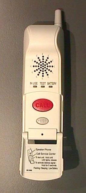
HHV20021106
Mar 25, 2003Emergency Portable Cellular Phone
Equipment Class
TNT - Licensed Non-Broadcast Transmitter Worn on Body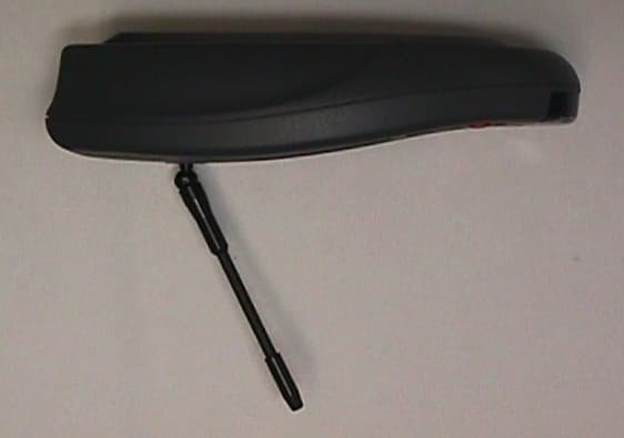
HHV20020606
Aug 19, 2002Emergency Communication Device
Equipment Class
TNB - Licensed Non-Broadcast Station TransmitterHHV26PBV4539919N
Apr 11, 1994Smoke Detector
Equipment Class
DSC - Part 15 Security/Remote Control TransmitterHHV26PECA249514N
Feb 28, 1993Security System Transmitter
Equipment Class
DSC - Part 15 Security/Remote Control TransmitterHHV26PECA249510N
Jul 15, 1991RF Smoke Detector Transmitter
Equipment Class
DSC - Part 15 Security/Remote Control Transmitter