HJR-X12-600-15Part 15.242 Medical Telemetry Transmitter
Welch Allyn, Inc.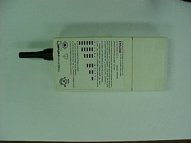
Click to zoom
Application Details
- Equipment Class
- DXX - Part 15 Low Power Communication Device Transmitter
- Date of Grant
- Sep 26, 2001
- Application Purpose
- Original Equipment
- Date of Application
- Sep 26, 2001
- Equipment Note
- Part 15.242 Medical Telemetry Transmitter
- Frequency Range
- 626.48000000 - 631.52000000
- Company
- Welch Allyn, Inc.
- Country
- United States
Documents & Files
Document Text
Text extracted from the exhibit documents filed with the FCC. Open a document above to read the original.
Users Manual
REF 9502-036-50 Ambulatory X-12 Operator’s Manual ______________________________________________________________________________ CAUTION: Federal law restricts this device for sale to and use by or on the order of a physician. ® Copyright© 2001 by Mortara Instrument, Inc. 7865 N. 86th Street Milwaukee, Wisconsin 53224 This document contains confidential information that belongs to Mortara Instrument, Inc. No part of this document may be transmitted, reproduced, used, or disclosed outside of the receiving organization without the express written consent of Mortara Instrument, Inc. Mortara is a registered trademark of Mortara Instrument, Inc. Ambulatory X- 12 is a trademark of Mortara Instrument, Inc. REF 9500-067-01 i Technical Support and Service Following are telephone numbers and addresses for contacting various technical support and service personnel. Mortara Instrument, Inc. 7865 N. 86th St. Milwaukee, WI 53224 Telephone Number: 414-354-1600 Toll-free Telephone Number: 800-231-7437 Toll-free Service Number: 888-MORTARA Fax: 414-354-4760 E-mail address: [email protected] 24 hour technical support Over 120 trained field service technicians Same day shipment of replacement parts Biomedical training classes Extended warranties/service contracts Sales Support/Supplies & Accessories Mortara Instrument, Inc. 7865 N. 86th St. Milwaukee, WI 53224 Phone: 414-354-1600 Fax: 414-354-4760 Internet: http://www.mortara.com European Economic Community Representative Mortara Rangoni Via Oradour, 7 40016 San Giorgio di Piano Bologna, Italy Phone: 39-51-6650-701 Fax: 39-51-6651-012 Additional International Support Offices Mortara France (France) Immeubles Burolines - Bat. 2 2 Ter, Rue Marcel Doret 31700 Blagnac Telephone number: 33-561-164000 Fax number: 33-561-164001 Mortara Instrument, Inc., GMBH (Germany) Henricistr. 124 45136 Essen Telephone number: 49-201-268311 Fax: 49-201-268313 Mortara Instrument, Inc., B.V. (The Netherlands). H. Dunantplein 6 3731 CL De Bilt Postbus 131 3720 AC Bilthoven Telephone number: 31-30-2205050 Fax: 31-30-2201531 ii Notices Manufacturer’s Responsibility Mortara Instrument, Inc., is responsible for the effects on safety, and performance only if • Assembly operations, extensions, re-adjustments, modifications or repairs are carried out by persons authorized by Mortara Instrument, • The electrical installation of the relevant room complies with the requirements of appropriate regulations, and • The Ambulatory X-12 is used in accordance with the instructions for use. Responsibility of the Customer The user of this product is responsible for ensuring the implementation of a satisfactory maintenance schedule. Failure to do so may cause undue failure and possible health hazards. Equipment Identification Mortara Instrument equipment is identified by serial numbers on the back or bottom of the device. Care should be taken so that these numbers are not defaced. Information pertinent to tracking and manufacturing is found under the battery compartment of the product and may be called upon if service of the device is required. Copyright and Trademark Notices This document contains information that is protected by copyright. All rights are reserved. No part of this document may be photocopied, reproduced or translated to another language without prior written consent of Mortara Instrument, Inc. The information contained in this document is subject to change without notice. Other Important Information The information in this document is subject to change without notice. Mortara Instrument, Inc., makes no warranty of any kind with regard to this material, including, but not limited to implied warranties of merchant ability and fitness for a particular purpose. Mortara Instrument, Inc., assumes no responsibility for any errors of omissions that may appears in this document. Mortara Instrument makes no commitment to update nor to keep current the information contained in this document. iii Warranty Information Your Mortara Warranty MORTARA INSTRUMENT, INC. (hereinafter referred to as “Mortara”) hereby warrants that Mortara products (hereinafter referred to as “Products”) shall be free from defects in material and workmanship under normal use, service and maintenance for one year of such Product from Mortara or an authorized distributor or representative of Mortara. Normal use, service and maintenance means operation and maintenance in accordance with appropriate instructions and/or information guides. This Warranty does not apply to damage to the Products caused by any or all of the following circumstances or conditions: a) Freight damage; b) Parts and/or accessories of the Products not obtained from or approved by Mortara; c) Misapplication, misuse, abuse and failure to follow the Product instruction sheets and/or information guides; d) Accident, a disaster affecting the Products; e) Alterations or modifications to the Products not authorized by Mortara; f) Other events outside of Mortara’s reasonable control or not arising under normal operating conditions. THE REMEDY UNDER THIS WARRANTY IS LIMITED TO THE REPAIR OR REPLACEMENT WITHOUT CHARGE FOR LABOR OR MATERIALS, OR ANY PRODUCTS FOUND UPON EXAMINATION BY MORTARA TO HAVE BEEN DEFECTIVE. This remedy shall be conditioned upon receipt of notice by Mortara of any alleged defects promptly after discovery thereof within the warranty period. Mortara’s obligations under the foregoing warranty will further be conditioned upon the assumption by the purchaser of the Products (i) of all carrier charges with respect to any Products returned to Mortara’s principal place or any other place as specifically designated by Mortara or an authorized distributor or representative of Mortara, and (ii) all risk of loss in transit. It is expressly agreed that the liability of Mortara is limited and that Mortara does not function as an insurer. A purchaser of a Product, by its acceptance and purchase thereof, acknowledges and agrees that Mortara is not liable…
Text truncated - open the document above for the full version.
Block Diagram
SPEAKERKEY PADDISPLAY CHANNEL SWITCHES AA Battery AA Battery SLIDE SWITCH SYSTEM CLOCK 5.12 MHZ ECG ANALOG TO DIGITAL CONVERTER MICROCONTROLLER RF OSCILLATOR AND MODULATOR MOC-600 PATIENT CABLEANTENNA POWER SUPPLY POWER SUPPLY FRONT END CARD MFC TRANSMITTER CARD MTC-600 X12-600 Block Diagram
Cover Letter(s)
Hi Jim, We have completed our review and have identified the following issues: 1. The form 731 quoted the grantee code to be HUR, however we believe it should be HJR. HUR is also used throughout the application. There is no need to correct the all the documentation as I will add an exhibit to the FCC filing to correct the error. However I would like a corrected tested report. The label has the correct code. Response – Revised test report supplied. 2. Please include in the manual information to the user and installer procedures to implement the requirements of 15.242 (d) and 15.242 (e). We do not currently find any information in the user's manual informing the user about their responsibilities with regard to coordination of use with existing TV stations and radio astronomy observatories. Response – Revised manual supplied. 3. Please confirm that device was tested in three orthogonal planes to maximize emissions. Response – Revised test report supplied. 4. Please include instructions in the manual that this device is for use solely on the premises of health care facilities. See 15.242 (a). Response – Revised manual supplied. Best regards Barry C. Quinlan Certification & Telecom Manager ------------------------------------------------------------------------------- Curtis-Straus LLC Voice: 978.486.8880 x270 527 Great Road Fax: 978.486.8828 Littleton, MA 01460 http://www.curtis-straus.com --------------------------------------------------------------------------------
External Photos
Mortara Instrument, Inc. X-12 Digital Transmitter for Medical Telemetry FCC ID#: HUR-X12-600-15 Photo One X-12 Digital Transmitter with Medical Patient Cable Attached for Monitoring Mortara Instrument, Inc. X-12 Digital Transmitter for Medical Telemetry FCC ID#: HUR-X12-600-15 Photo Two X-12 Digital Transmitter Front Cover Mortara Instrument, Inc. X-12 Digital Transmitter for Medical Telemetry FCC ID#: HUR-X12-600-15 Photo Three X-12 Digital Transmitter Back Cover
ID Label/Location Info
Mortara Instrument, Inc. X-12 Digital Transmitter for Medical Telemetry FCC ID#: HUR-X12-600-15 Photo Four X-12 Digital FCC ID Label Close-up
Internal Photos
Mortara Instrument, Inc. X-12 Digital Transmitter for Medical Telemetry FCC ID#: HUR-X12-600-15 Photo Six Battery Pack Removed to Expose Programming Switches Mortara Instrument, Inc. X-12 Digital Transmitter for Medical Telemetry FCC ID#: HUR-X12-600-15 Photo Seven Open for Inspection Mortara Instrument, Inc. X-12 Digital Transmitter for Medical Telemetry FCC ID#: HUR-X12-600-15 Photo Nine Digital Processing on Transmitter PCB Mortara Instrument, Inc. X-12 Digital Transmitter for Medical Telemetry FCC ID#: HUR-X12-600-15 Photo Ten Digital Processing PCB Flip Side RF PCB shown with Shield Cover Removed Mortara Instrument, Inc. X-12 Digital Transmitter for Medical Telemetry FCC ID#: HUR-X12-600-15 Photo Eleven RF PCB Close-up Mortara Instrument, Inc. X-12 Digital Transmitter for Medical Telemetry FCC ID#: HUR-X12-600-15 Photo Twelve RF PCB Close-up with Shield Removed Mortara Instrument, Inc. X-12 Digital Transmitter for Medical Telemetry FCC ID#: HUR-X12-600-15 Photo Thirteen Close-up of Antenna Connection Note: See the following FCC Approval Statement for the use of this Connector with Modified Antenna Boot.
Operational Description
X12-600 Theory of Operation 8/7/01 X12-600 Overview The X12-600 is an ECG amplifier with digital conversion and integrated RF transmitter. The ECG amplifier is a 12 lead device with diagnostic quality digital conversion. The RF transmitter operates in the TV channels 37 through 41 (608 to 632 MHz) meeting FCC Part 15.242. The X12 has a detachable light weight 12 lead patient cable. The X12-600 operates from 2 AA Alkaline batteries for over 30 Hours. When the battery compartment is removed, a power switch and RF channel select switches are exposed. The front panel has a two button keypad and a 51x27 mm segment LCD. The overall dimensions are 140x67x25 mm. The X12 is made up of two circuit boards sandwiched together inside the unit. A single 8 pin header provides interconnectivity. The two boards are the Mortara Front End Card (MFC) and the Mortara Transmit Card (MTC). The MFC is screwed to the back half of the plastic housing. The MTC is screwed to the front plastic housing. The LCD is held in place by the MTC with conductive rubber strips. The rubber strips pass the electrical signals from the MTC to the LCD. Exiting from the top of the unit is a 45mm long antenna. Internal attachment to the PC board is via a standard SMA connector. The antenna is collared by the case thus it is not replaceable unless the case is disassembled. The case mounting screws are hidden by the back label preventing easy removal. The mechanical antenna capture technique is identical to the FCC approved X12-915 (HJR-X12-915). Mortara Front End Card (MFC) The MFC is a low power ECG front end that converts the analog patient signals to digital data. The MFC is designed to operate in handheld or portable devices and to operate from two AA alkaline batteries. The MFC has the patient cable connector mounted directly on the PC board. The digital data and clock interface to the transmit card is through an 8 pin header. There is no isolation boundary required for this board so all signals and power lines connect directly to the transmitter. The two AA Alkaline batteries connect to the MFC through the slide switch. The battery voltage is stepped up to 5 volts by switching regulators U2. This step up supply can operate with the two AA batteries down to ½ volt each. This effectively uses all the energy stored in the batteries. The 5V output is first linear regulated (U3) to 4.3V and then linear regulated (U4) to 3.3V. The 4.3V is only used to power the linear op amps. The 3.3V is 1% accurate and powers the custom A/D converter, voltage references, and other logic components. The linear regulator U3 keeps the MFC in reset until the supply is within operating range. The ECG signals are digitized by a custom 8 channel A/D converter with 20 bit resolution (U1). The A/D is clocked by the 5.12 MHZ clock from the transmit card. The true sample rate for each channel is 10 KHz. A 2.56 MHz serial data stream comprised of all 8 channels encoded in 32 bit packets is sent to the transmit card for processing . Mortara Transmit Card (MTC-600) The X12-600 processing is performed by a Motorola 68HC711 microcontroller on the MTC board. The microcontroller runs at the system clock speed of 5.12 MHz. Besides processing the digital ECG data the microcontroller performs the following tasks. *Writing data to the LCD controller (U13). *Reading the RF channel select switches (S2 and S3). *Reading the key pad. *Activating the speaker tones. *Program the RF oscillator phase locked channel. The two AA Alkaline batteries connect to the MTC through the slide switch. The battery voltage is stepped up to 3.3 by switching regulator U3. This step up supply can operate with the two AA batteries down to ½ volt each. This effectively uses all the energy stored in the batteries. U2 provides a regulation drop out flag that will reset the processor when the 3.3V switcher supply drops below a defined threshold. This condition occurs either at start-up or at battery depletion. Either case, halting the processor prevents transmission of erroneous data or other system malfunction until the supplies are valid. The microcontroller, other logic, and RF oscillator are all powered by the 3.3V supply. The RF oscillator is controlled by a phase locked loop (PLL). The PLL is programmed by the microcontroller based on the channel switch settings. The channel switches and subsequently the channel itself have hexadecimal labels. The lowest channel is 00 and the highest channel is FF. The Table I. below lists the channel numbers and the center RF frequencies. The 2.56 MHz serial data stream from the MFC A/D converter is first processed by U9 the Receiver Gate Array. This device decimates the 10KHz sample rate and formats the data for each sample and channel into two 16 bit words. The effective sample rate out the Receiver is 500 Hz for each channel. The output data is dumped into FIFO’s U7 and U9. When the microcontroller U4 is ready, it reads the data samples from the FIFO’s. The microcontroller processes the ECG data including detecting lead fail. If lead fail is detected the display driver is also informed resulting in the lead fail message being displayed. If in the impedance check mode the microcontroller detects the small stimulus voltages in the data for its magnitude and derives the quality of electrode placement. Finally, the ECG data, lead fail data, error correction, RF channel number, pace maker detect, and ancillary data is formatted into a 40K baud serial data stream. This data stream is Gaussian Filtered then FM modulates the RF carrier with a 20 KHz deviation. SPEAKERKEY PADDISPLAY CHANNEL SWITCHES AA Battery AA Battery SLIDE SWITCH SYSTEM CLOCK 5.12 MHZ ECG ANALOG TO DIGITAL CONVERTER MICROCONTROLLER RF OSCILLATOR AND MODULATOR MOC-600 PATIENT CABLEANTENNA POWER SUPPLY POWER SUPPLY FRONT END CARD MFC TRANSMITTER CARD MTC-600 X12-600 Block Diagram Table I. X12-600 Channel Assignments TV37TV38TV39TV40 CH#MHzCH#MHzCH#MHzCH#MHz 00608.4840614.4880620.48C0626.48 01608.…
Text truncated - open the document above for the full version.
Test Report
L. S. COMPLIANCE, Inc. FCC ID: HJR-X12-600-15 LSC-Mortara-Medical Tx-301314 Page 0 of 39 COMPLIANCE TESTING OF THE X12-600 Medical Telemetry Transmitter - TEST REPORT - Project Number: 301314 Prepared for: Brian Sueppel Mortara Instrument, Inc. 7865 North 86 th Street MILWAUKEE, WI 53224 Date(s) tests were performed: August 9 th , 2001 All results of this report relate only to the items that were tested. This report is not to be reproduced, except in full, without written approval of L.S.Compliance, Inc. L. S. COMPLIANCE, Inc. FCC ID: HJR-X12-600-15 LSC-Mortara-Medical Tx-301314 Page 1 of 39 Table of Contents: Section Description Page # Index 1 1.1 Description of Measurement Facilities 2 1.2 Signature Page 3 1.3 Summary of Test Report 4 1.4 Introduction 5 1.5 Purpose 5 1.6 Radiated Emission Test Setup 5 1.7 Radiated Emission Test Procedure 6 1.8 Test Equipment Utilized for Radiated Emission 7 1.9 Restricted Bands (Frequencies and Limits) 8 1.10 Photos taken during testing 9 1.11 Summary of Results and Conclusions 12 1.12 Test Equipment List 13 Appendices A Sample Calculations: 14 I Calculation of Radiated Emissions Limits 15 B Data Charts 16 C Graphs 18 L. S. COMPLIANCE, Inc. FCC ID: HJR-X12-600-15 LSC-Mortara-Medical Tx-301314 Page 2 of 39 1.1 DESCRIPTION OF MEASUREMENT FACILITIES Site on File with the FCC ID Number: 31040/SIT 1300F2 “ The site referenced above has been found to comply with the test site criteria found in ANSI C63.4-1992 and Title 47CFR, FCC Part 15 Section 2.948.” L. S. COMPLIANCE, Inc. FCC ID: HJR-X12-600-15 LSC-Mortara-Medical Tx-301314 Page 3 of 39 1.2 SIGNATURE PAGE SIGNATURE PAGE Prepared By: August9 th 2001 Date Approved By: August 9 th , 2001 Kenneth L. Boston, EMC Lab Manager Date PE #31926 Registered Professional Engineer (State of Wisconsin) L. S. COMPLIANCE, Inc. FCC ID: HJR-X12-600-15 LSC-Mortara-Medical Tx-301314 Page 4 of 39 1.3 SUMMARY OF TEST REPORT MANUFACTURER: Mortara Instrument, Inc. MODEL: X12-600 SERIAL: 30012-006-1000A DESCRIPTION: X12-600 Medical Telemetry Transmitter The X12-600 medical telemetry transmitter was found to MEET the radiated emission specification of Title 47 CFR, FCC Part 15, subpart C, for an intentional radiator. No conducted emissions tests were performed, due to the product not being powered off of the public AC power mains. The X12-600 medical telemetry transmitter was also found to MEET the radiated emission specification of Title 47 CFR FCC Part 15, subpart B for emissions with regards to the class B digital sections of the product. This product is a composite device, with the digital section subject to verification. Therefore this technical report will primary contain data that is pertinent to the certification of the transmitter section of the product. L. S. COMPLIANCE, Inc. FCC ID: HJR-X12-600-15 LSC-Mortara-Medical Tx-301314 Page 5 of 39 1.4 INTRODUCTION On August 9 th , 2001, a series of Radiated Emissions tests were performed on a sample model of the Medical Telemetry Transmitter. The X12-600 is an ECG amplifier with digital conversion and integrated RF transmitter. The ECG amplifier is a 12 lead device with diagnostic quality digital conversion. The RF transmitter operates in the TV channels 37 through 41 (608 to 632 MHz) meeting FCC Part 15.242. The X12 has a detachable light weight 12 lead patient cable. The X12-600 operates from two AA Alkaline batteries for over 30 hours. When the battery compartment is removed, a power switch and RF channel select switches are exposed. The front panel has a two button keypad and a 51x27mm segment LCD. The overall dimensions are 140x67x25 mm. These tests were performed using the test procedures outlined in ANSI C63.4-1992 for intentional radiators, and in accordance with the general limits set forth in FCC Part 15.242 and 15.209 for a low power transmitter. Tests were also performed as outlined in ANSI C63.4- 1992 for non-intentional radiators, in order to allow verification of emissions from the digital section of the product. These tests were performed by Thomas T. Lee, of L. S. Compliance, Inc. and witnessed by Brian Sueppel of Mortara Instruments, Inc. 1.5 PURPOSE The above mentioned tests were performed in order to determine the compliance of the product with limits contained in various provisions of Title 47 CFR, FCC Part 15, including: 15.209 15.242 All radiated emissions tests were performed to measure the emissions in the frequency bands described by the above sections, and to determine whether said emissions are below the limits established by the above sections. These tests were performed in accordance with the procedure described in the American National Standard for methods of measurement of Radio-Noise Emissions from Low-Voltage Electrical and Electronic Equipment in the Range of 9 kHz to 40 GHz (ANSI C63.4-1992). Another document used as reference for the EMI receiver specification was the International Special Committee on Radio Interference (CISPR) number 16-1 (1993). 1.6 RADIATED EMISSIONS TEST SETUP The test sample was operated within the 3 meter Semi-Anechoic, FCC listed chamber located at L.S. Compliance in Cedarburg, WI. The test sample was operated using two AA alkaline batteries. The battery voltage is stepped up to 5 volts by switching regulators U2. This step up supply can operate with the two AA batteries down to ½ volt each. This effectively uses all the energy stored in the batteries. The test sample was positioned upon an 80cm high wooden table, which was positioned upon the 2meter turntable within the chamber. The measurement antenna, mounted upon a motorized mast was then placed 3 meters from the product perimeter. This allowed the test sample to be scanned in both azimuth and elevation. Measurements were performed for the transmitter fundamental, and harmonics up through the 10 th harmonic, although harmonics above the 4 th harmonic could not be seen in the noise floor. The test sample was set to operate on one of three channels available within …
Text truncated - open the document above for the full version.
Test Setup Photos
L. S. COMPLIANCE, Inc. FCC ID: HJR-X12-600-15 LSC-Mortara-Medical Tx-301314 Page 10 of 39 Close up front view of the X12-600 during the Radiated Emissions tests on the 3-Meter FCC listed Semi-anechoic chamber L. S. COMPLIANCE, Inc. FCC ID: HJR-X12-600-15 LSC-Mortara-Medical Tx-301314 Page 11 of 39 Side view of the X12-600 during the Radiated Emissions tests on the 3-Meter Semi-anechoic Chamber
Contact Information
Applicant
Robert Berry(Regulatory Affairs Manager)
Test Firm
LS Research, LLCRyan Urness
Technical Specifications
| # | Rule Parts | Frequency Range | Power Output |
|---|---|---|---|
| 4 | 15C | 626.48 MHz - 631.52 MHz | - |
Other Applications from Welch Allyn, Inc.
HJR-X12P-2500
Nov 18, 2004Telemetry Transmitter for Medical Applications
Equipment Class
DXX - Part 15 Low Power Communication Device TransmitterHJR-MRM-915
Jul 24, 1994Medical Telemetry Receiver Module for use in Mortara Instrument Products.
Equipment Class
CYY - Communications Receiver used w/Pt 15 TransmitterHJR-X12-915
Jul 24, 1994Medical Telemetry Transmitter
Equipment Class
DXX - Part 15 Low Power Communication Device Transmitter