HJR-X12P-2500Telemetry Transmitter for Medical Applications
Welch Allyn, Inc.Application Details
- Equipment Class
- DXX - Part 15 Low Power Communication Device Transmitter
- Date of Grant
- Nov 18, 2004
- Application Purpose
- Original Equipment
- Date of Application
- Nov 18, 2004
- Equipment Note
- Telemetry Transmitter for Medical Applications
- Frequency Range
- 2400.00000000 - 2483.50000000
- Company
- Welch Allyn, Inc.
- Country
- United States
Documents & Files
Document Text
Text extracted from the exhibit documents filed with the FCC. Open a document above to read the original.
Users Manual
P/N 9515-164-50-ENG X12+ User Manual __________________________________________________________________________________________ CAUTION: Federal law restricts this device for sale to and use by or on the order of a physician. ® Copyright © 2004 by Mortara Instrument, Inc. 7865 N. 86th Street Milwaukee, Wisconsin 53224 This document contains confidential information that belongs to Mortara Instrument, Inc. No part of this document may be transmitted, reproduced, used, or disclosed outside of the receiving organization without the express written consent of Mortara Instrument, Inc. Mortara is a registered trademark of Mortara Instrument, Inc. Ambulatory X12+ is a trademark of Mortara Instrument, Inc. REF NEW i Technical Support and Service Headquarters Mortara Instrument, Inc. 7865 North 86th Street Milwaukee, WI 53224 Tel: 414.354.1600 Tel: 800.231.7437 Fax: 414.354.4760 Internet: http://www.mortara.com Europe Economic Community Representative Mortara Rangoni Europe, Srl (European Headquarters, Italy) Via Oradour 7 40016 S. Giorgio di Piano, BO Tel: +39.051.6654311 Fax: +39.051.6651012 Service/Technical Support Group Mortara Instrument, Inc. 7865 North 86th Street Milwaukee, WI 53224 Tel: 414.354.1600 Service: 888.MORTARA (888.667.8272) Fax: 414.354.4760 E-mail: [email protected] 24 Hour Technical Support Same Day Shipment of Replacement Parts Biomedical Training Classes Extended Warranties/Service Contracts Sales Support/ Supplies & Accessories Mortara Instrument, Inc. 7865 North 86th Street Milwaukee, WI 53224 Tel: 414.354.1600 Fax: 414.354.4760 E-mail: [email protected] Mortara Instrument GmbH (Germany) Kaninenberghöhe 50 45136 Essen Tel: +49.201.268311 Fax: +49.201.268313 Mortara Instrument B.V. (The Netherlands) H. Dunantplein 6 3731 CL De Bilt Postbus 131 3720 AC Bilthoven Tel: +31.30.2205050 Fax: +31.30.2201531 ii Notices Manufacturer’s Responsibility Mortara Instrument, Inc., is responsible for the effects on safety and performance only if: • Assembly operations, extensions, readjustments, modifications or repairs are carried out only by persons authorized by Mortara Instrument, Inc. • The device (Ambulatory X12+) is used in accordance with the instructions for use. Responsibility of the Customer The user of this product is responsible for ensuring the implementation of a satisfactory maintenance schedule. Failure to do so may cause undue failure and possible health hazards. Equipment Identification Mortara Instrument, Inc. equipment is identified by a serial and reference number on the back of the device. Care should be taken so that these numbers are not defaced. Copyright and Trademark Notices This document contains information that is protected by copyright. All rights are reserved. No part of this document may be photocopied, reproduced or translated to another language without prior written consent of Mortara Instrument, Inc. Other Important Information The information in this document is subject to change without notice. Mortara Instrument, Inc. makes no warranty of any kind with regard to this material including, but not limited to, implied warranties of merchantability and fitness for a particular purpose. Mortara Instrument, Inc. assumes no responsibility for any errors or omissions that may appear in this document. Mortara Instrument Inc. makes no commitment to update or to keep current the information contained in this document. iii Warranty Information Your Mortara Warranty MORTARA INSTRUMENT, INC. (hereinafter referred to as “Mortara”) hereby warrants that Mortara products (hereinafter referred to as “Products”) shall be free from defects in material and workmanship under normal use, service and maintenance for the warranty period of such Product from Mortara or an authorized distributor or representative of Mortara. The warranty period is defined as twelve (12) months following the date of shipment from Mortara. Normal use, service and maintenance means operation and maintenance in accordance with appropriate instructions and/or information guides. This Warranty does not apply to damage to the Products caused by any or all of the following circumstances or conditions: a) Freight damage; b) Parts and/or accessories of the Products not obtained from or approved by Mortara; c) Misapplication, misuse, abuse and failure to follow the Product instruction sheets and/or information guides; d) Accident, a disaster affecting the Products; e) Alterations or modifications to the Products not authorized by Mortara; f) Other events outside of Mortara’s reasonable control or not arising under normal operating conditions. THE REMEDY UNDER THIS WARRANTY IS LIMITED TO THE REPAIR OR REPLACEMENT WITHOUT CHARGE FOR LABOR OR MATERIALS, OR ANY PRODUCTS FOUND UPON EXAMINATION BY MORTARA TO HAVE BEEN DEFECTIVE. This remedy shall be conditioned upon receipt of notice by Mortara of any alleged defects promptly after discovery thereof within the warranty period. Mortara’s obligations under the foregoing warranty will further be conditioned upon the assumption by the purchaser of the Products (i) of all carrier charges with respect to any Products returned to Mortara’s principal place or any other place as specifically designated by Mortara or an authorized distributor or representative of Mortara, and (ii) all risk of loss in transit. It is expressly agreed that the liability of Mortara is limited and that Mortara does not function as an insurer. A purchaser of a Product, by its acceptance and purchase thereof, acknowledges and agrees that Mortara is not liable for loss, harm or damage due directly or indirectly to an occurrence or consequence therefrom relating to the Products. If Mortara should be found liable to anyone under any theory (except the expressed warranty set forth herein) for loss, harm or damage, the liability of Mortara shall be limited to the lesser of the actual loss, harm or damage, or the original purchase price of the Product when sold. EXCLUDED FROM THE LIMITED WAR…
Text truncated - open the document above for the full version.
Cover Letter(s)
Response to TCB Findings 1. The label is missing the "ID" after the "FCC". It should read as "FCC ID". Please supply a corrected label sample. Revised label drawing supplied. 2. Complete user/instruction manual must be supplied. The copy submitted appears to be first 11 pages of the manual. Please supply the whole manual. Complete user’s manual supplied. 3. Please note that the band-edge compliance must be shown with regular BW settings used above 1GHz, namely 1MHz RBW and VBW. If this causes significant contribution from the fundamental near the band-edge and cause it to fail, then marker delta method of DA 00-705 can be used to show compliance. Please supply test data showing compliance at the band-edges with 1MHz RBW & VBW. Revised test report supplied.
External Photos
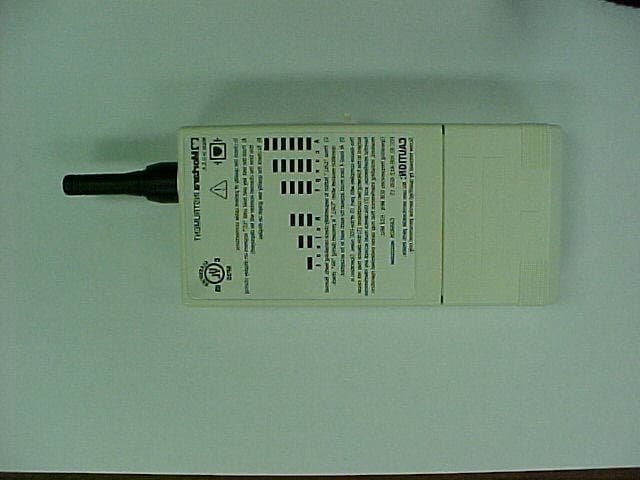
Mortara Instrument, Inc. X-12+ Digital Transmitter for Medical Telemetry 2.4GHz ISM Band FCC ID#: HJR-X12P-2500 Photo One – External Module configuration with ¼ wave monopole antenna Mortara Instrument, Inc. X-12+ Digital Transmitter for Medical Telemetry 2.4GHz ISM Band FCC ID#: HJR-X12P-2500 Photo Two – External Module Patient Connector Mortara Instrument, Inc. X-12+ Digital Transmitter for Medical Telemetry 2.4GHz ISM Band FCC ID#: HJR-X12P-2500 Photo Three – External Module FCC Label and Battery Compartment Mortara Instrument, Inc. X-12+ Digital Transmitter for Medical Telemetry 2.4GHz ISM Band FCC ID#: HJR-X12P-2500 Photo Four – External Close-Up of FCC ID Label
ID Label/Location Info
9050 - 057 - 02 "ELECTRONIC ORIGINAL" Any Changes To This Document Done Manually Void The Data Base Original. DRAWN BY: DATE: DATE: DATE: DATE: DATE: DATE: DOCUMENTATION CHECKED BY: ENGINEERING APPROVED BY: MANUFACTURING APPROVED BY: Q.A. APPROVED BY: OTHER: TITLE: LATEST DOCUMENT CHANGE: DR: ECO: DATE: BY: PART NUMBER: SCALE: SHEET 1 OF 2 7865 N. 86th STREET, MILWAUKEE, WI 53224 TEL. 414-354-1600 GRZinda 03-03-04 CONFIDENTIAL This print and the design therein represented are the property of Mortara Instrument, Incorporated, and may not be used in any manner detrimental to its interest. This print has been issued with the understanding that it will not be reproduced, that no disclosure of its contents will be made to others, that it will not be used for manufacture for others, and will be returned upon request. LABEL X12+ NAMEPLATE 2500MHz FULL REV: B1 Notes: 1. Material: 0.010 Velvet Polycarbonate Adhesive: MIS-01-022-02 2. Text Copy: Mortara Black per MIS-01-021-05. Background: Mortara White per MIS-01-021-03. 3. The label shall be a “UL” recognized marking and labeling system, for use on various metals, painted surfaces, and plastic, to indicate conformance to this requirement, the supplier shall identify conformance with appropriate markings on direct packaging. 4. Lines depicting label borders are for reference only and should not appear on finished copy. Finish: .Three coats dense white ink for opacity Measurements in Inches Tolerance: +/-.006 unless otherwise noted. 2.102 TYP 2 PLACES R 0.120 TYP 2 PLACES 0.904 TYP 2 PLACES R 0.080 TYP 4 PLACES R 0.127 TYP 2 PLACES 0.312 2.748 3.100 1 5524 11-17-04 GRZinda 0459 AA c U L US SI F S I A E LD C RR 5P35 UL2601-1, IEC60601-1 CAN/CSA C22.2 No. 601.1 IEC60601-2-25 This device complies with part 15 of the FCC rules. Operation is subject to the following two conditions: (1) this device may not cause harmful interference, and (2) this device must accept any interference received, including interference that may cause undesired operation. FCC ID: HJR-X12P-2500 INSTRUMENT Milwaukee, WI U.S.A. Model: X12+ MEDICAL EQUIPMENT PAGE:SCALE : PART NUMBER: REV: 2 of 2 NTS9050 - 057 - 02 B1
Internal Photos
Mortara Instrument, Inc. X-12+ Digital Transmitter for Medical Telemetry 2.4GHz ISM Band FCC ID#: HJR-X12P-2500 Photo One – Internal Open for Inspection Mortara Instrument, Inc. X-12+ Digital Transmitter for Medical Telemetry 2.4GHz ISM Band FCC ID#: HJR-X12P-2500 Photo Two – Internal RF / Control Digital PCB exposing Patient Interface PCB Mortara Instrument, Inc. X-12+ Digital Transmitter for Medical Telemetry 2.4GHz ISM Band FCC ID#: HJR-X12P-2500 Photo Three – Internal RF / Control Digital PCB Mortara Instrument, Inc. X-12+ Digital Transmitter for Medical Telemetry 2.4GHz ISM Band FCC ID#: HJR-X12P-2500 Photo Four – Internal Flip Side showing RF PCB Module Mortara Instrument, Inc. X-12+ Digital Transmitter for Medical Telemetry 2.4GHz ISM Band FCC ID#: HJR-X12P-2500 Photo Five – Internal Antenna to RF Module Mortara Instrument, Inc. X-12+ Digital Transmitter for Medical Telemetry 2.4GHz ISM Band FCC ID#: HJR-X12P-2500 Photo Six – Internal Antenna Module – Ground Plane Side Mortara Instrument, Inc. X-12+ Digital Transmitter for Medical Telemetry 2.4GHz ISM Band FCC ID#: HJR-X12P-2500 Photo Seven – Internal Antenna PCB Shield Removed Mortara Instrument, Inc. X-12+ Digital Transmitter for Medical Telemetry 2.4GHz ISM Band FCC ID#: HJR-X12P-2500 Photo Eight – Internal RF PCB Close-Up
Test Report
L.S. Compliance, Inc. W66 N220 Commerce Court Cedarburg, WI 53012 262-375-4400 Fax: 262-375-4248 COMPLIANCE TESTING OF : X12 + Transmitter PREPARED FOR : Mortara Instrument, Incorporated Attn.: Mr. Brian Sueppel 7865 North 86 th Street Milwaukee, WI 53224 TEST REPORT NUMBER : 304274-TCB Rev. 1 TEST DATE(S) : June 21 ST - 25 TH , 2004 All results of this report relate only to the items that were tested. This report is not to be reproduced, except in full, without written approval of L. S. Compliance, Inc. L.S. Compliance, Inc. Page 2 of 25 Test Report Number: 304274-TCB Rev. 1 Prepared For: Mortara Instrument, Inc. Table of Contents Section Description Page Index 2 1 L. S. Compliance in Review 3 2 A2LA Certificate of Accreditation 4 3 A2LA Scope of Accreditation 5 4 Validation Letter-U.S. Competent Body for EMC Directive 89/336/EEC 6 5 Signature Page 7 6 Product and General Information 8 7 Introduction 8 8 Product Description 8 9 Test Requirements 9 10 Summary of Test Report 9 11 Radiated Emissions Test 10-20 12 Conducted Emissions Test, AC Power Line 21 13 Band-Edge Measurements 22 14 Frequency and Power Stability across input voltage 23 Appendix A Test Equipment List 24 L.S. Compliance, Inc. Page 3 of 25 Test Report Number: 304274-TCB Rev. 1 Prepared For: Mortara Instrument, Inc. 1. L. S. Compliance In Review L.S. Compliance - Accreditations and Listing’s As an EMC Testing Laboratory, our Accreditation and Assessments are recognized through the following: A2LA – American Association for Laboratory Accreditation Accreditation based on ISO/IEC 17025 : 1999 with Electrical (EMC) Scope of Accreditation A2LA Certificate Number: 1255.01 Federal Communications Commission (FCC) – USA Listing of 3 Meter Semi-Anechoic Chamber based on Title 47 CFR – Part 2.948 FCC Registration Number: 90756 Listing of 3 and 10 meter OATS based on Title 47CFR – Part 2.948 FCC Registration Number: 90757 Industry Canada On file, 3 Meter Semi-Anechoic Chamber based on RSS-212 – Issue 1 File Number: IC 3088-A On file, 3 and 10 Meter OATS based on RSS-212 – Issue 1 File Number: IC 3088 U. S. Conformity Assessment Body (CAB) Validation Validated by the European Commission as a U. S. Competent Body operating under the U. S. /EU, Mutual Recognition Agreement (MRA) operating under the European Union Electromagnetic Compatibility –Council Directive 89/336/EEC, Article 10.2. Date of Validation: January 16, 2001 Validated by the European Commission as a U.S. Notified Body operating under the U.S./EU, Mutual Recognition Agreement (MRA) operating under the European Union Telecommunication Equipment – Council Directive 99/5/EC, Annex V. Date of Validation: November 20, 2002 Notified Body Identification Number: 1243 L.S. Compliance, Inc. Page 4 of 25 Test Report Number: 304274-TCB Rev. 1 Prepared For: Mortara Instrument, Inc. 2. A2LA Certificate of Accreditation L.S. Compliance, Inc. Page 5 of 25 Test Report Number: 304274-TCB Rev. 1 Prepared For: Mortara Instrument, Inc. 3. A2LA Scope of Accreditation L.S. Compliance, Inc. Page 6 of 25 Test Report Number: 304274-TCB Rev. 1 Prepared For: Mortara Instrument, Inc. 4. Validation Letter – U.S. Competent Body for EMC Directive 89/336/EEC L.S. Compliance, Inc. Page 7 of 25 Test Report Number: 304274-TCB Rev. 1 Prepared For: Mortara Instrument, Inc. 5. Signature Page Prepared By: November 15, 2004 Teresa A. White, Document Coordinator Date Tested By: November 15, 2004 Abtin Spantman, EMC Engineer Date Approved By: November 15, 2004 Kenneth L. Boston, EMC Lab Manager Date PE #31926 Licensed Professional Engineer Registered in the State of Wisconsin, United States L.S. Compliance, Inc. Page 8 of 25 Test Report Number: 304274-TCB Rev. 1 Prepared For: Mortara Instrument, Inc. 6. Product and General Information Manufacturer: Mortara Instrument, Inc. Date(s) of Test: June 21 ST – 25 TH , 2004 Test Engineer(s): Tom Smith √ Abtin Spantman Ken Boston Model #: X12 + Serial #: Proto #2 Voltage: 1.5 VDC Operation Mode: Normal and Continuous Transmit 7. Introduction Between June 21 ST and 25 TH , 2004 a series of Conducted and Radiated Emission tests were performed on one sample of the Mortara Instrument model number X12+ transmitter, serial number “Proto #2”, here forth referred to as the “Equipment Under Test” or “EUT”. These tests were performed using the procedures outlined in ANSI C63.4-2003 for intentional radiators, and in accordance with the limits set forth in FCC Part 15.249 (Industry Canada RSS-210) for a low power transmitter. These tests were performed by Abtin Spantman, EMC Engineer of L.S. Compliance, Incorporated and witnessed by Brian Sueppel of Mortara Instrument, Incorporated. All Radiated and Conducted Emission tests were performed upon the EUT to measure the emissions in the frequency bands described in Title 47 CFR, FCC Part 15, including 15.35, 15.209, 15.249 and Industry Canada RSS-210 to determine whether these emissions are below the limits expressed within the standards. These tests were performed in accordance with the procedures described in the American National Standard for methods of measurement of Radio- Noise Emissions from Low-Voltage Electrical and Electronic Equipment in the Range of 9 kHz to 40 GHz (ANSI C63.4-2003). Another document used as a reference for the EMI Receiver specification was the Comite International Special Des Perturbations Radioelelectriques (CISPR) Number 16-1, 2002. 8. Product Description The X12+ (2500) is a patient worn telemetry transmitter used in hospitals and clinics for the transmission of ECG data. The transmitter is made up of an ECG amplifier, microprocessor, and RF transmitter. The ECG amplifier is a 12 lead device with diagnostic quality response and digital conversion. The microprocessor formats the ECG data for transmission, handles user I/O, and sets the RF transmission channel. The RF transmitter operates in the 2.4 GHz ISM band, on 256 channels, and is designed to meet FCC rules Part 15.249. The modulation of the carrier is …
Text truncated - open the document above for the full version.
Test Setup Photos
Page 1 of 2 Mortara Instrument Test Setup Photos Photos Taken During Radiated Emission Testing View of the EUT setup in vertical orientation View of the EUT setup in Horizontal orientation View of the EUT setup in Side orientation Page 2 of 2 View of the equipment setup with the simulated patient connected. View of the equipment setup without the simulated patient.
Contact Information
Applicant
Robert Berry(Regulatory Affairs Manager)
Test Firm
LS Research, LLCRyan Urness
Technical Specifications
| # | Rule Parts | Frequency Range | Power Output |
|---|---|---|---|
| 1 | 15C | 2.40 GHz - 2.48 GHz | - |
Other Applications from Welch Allyn, Inc.
HJR-X12-600-15
Sep 26, 2001Part 15.242 Medical Telemetry Transmitter
Equipment Class
DXX - Part 15 Low Power Communication Device TransmitterHJR-MRM-915
Jul 24, 1994Medical Telemetry Receiver Module for use in Mortara Instrument Products.
Equipment Class
CYY - Communications Receiver used w/Pt 15 TransmitterHJR-X12-915
Jul 24, 1994Medical Telemetry Transmitter
Equipment Class
DXX - Part 15 Low Power Communication Device Transmitter