HSW-2410NF2.4 GHz SPREAD SPECTRUM TRANSCEIVER
Murata Electronics North America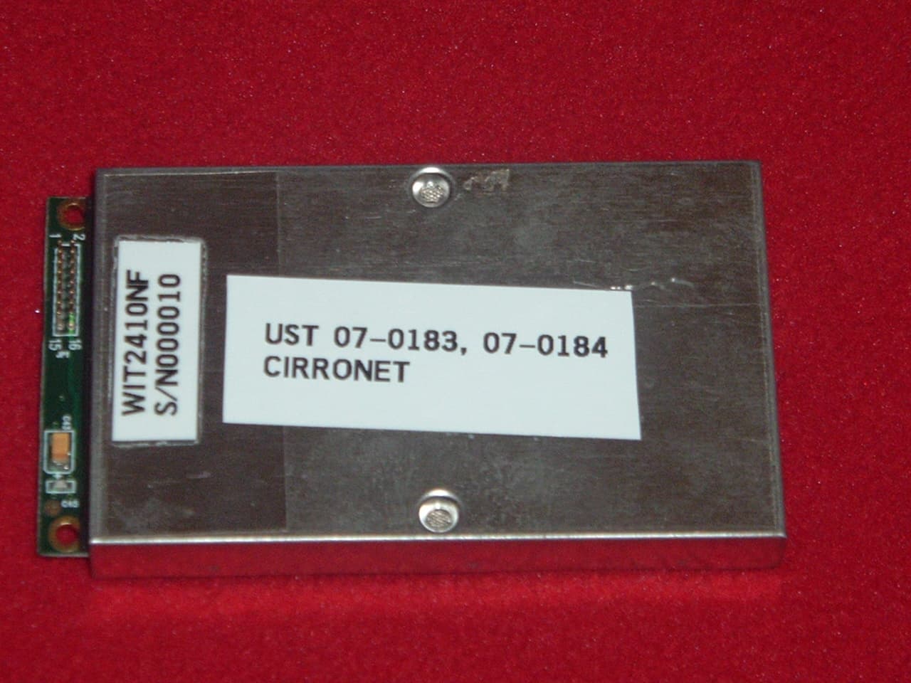
Click to zoom
Application Details
- Equipment Class
- DSS - Part 15 Spread Spectrum Transmitter
- Date of Grant
- Sep 18, 2007
- Application Purpose
- Original Equipment
- Date of Application
- Sep 17, 2007
- Equipment Note
- 2.4 GHz SPREAD SPECTRUM TRANSCEIVER
- Frequency Range
- 2401.68960000 - 2469.88800000
- Country
- United States
Documents & Files
Document Text
Text extracted from the exhibit documents filed with the FCC. Open a document above to read the original.
Cover Letter(s)
Tuesday, August 17, 2007 Dear Application Examiner Regarding Part 15 Unlicensed Modular Transmitter Approval, the following requirements called out in FCC Public Notice DA 00-1407 are observed: 1. The WIT2410NF has its own RF shielding. 2. The WIT2410NF modular transmitter has buffered modulation/data inputs to ensure that the module will comply with Part 15 requirements under conditions of excessive data rates or over- modulation. 3. The WIT2410NF employs on board power supply regulation. 4. The WIT2410NF employs a MMCX connector. Professional installation is required. 5. The WIT2410NF was tested in a stand-alone configuration. 6. The WIT2410NF has a label with the FCC ID: HSW-2410NF 7. The WIT2410NF complies with FCC DTS for Frequency Hopping Spread Spectrum Operation. An Integration Guide is provided for every module sold. This guide instructs the user in the proper operation of the device. The text in the guide specifies FCC Part 15 compliance: 8. The use of the WIT2410NF in any application where the antenna is 20 cm or less distance to the body is not allowed. This is specified in the Integration Guide previous to the Table of Contents. The text follows: Maximum Permissible Exposure (MPE) Limits • Information to user/installer regarding FCC s Maximum Permissible Exposure (MPE) limits. • Notice to users/installers using the following fixed antenna, with Cirronet products containing the RF module WIT2410NF The field strength radiated by this antenna, when connected to the WIT2410NF Cirronet RF module, may exceed FCC mandated RF exposure limits. FCC rules require installation of these antennas in such a way that the general public will not be closer than 20 cm from the radiating aperture of any of these antennas. End users of these systems must also be informed that RF exposure limits may be exceeded if personnel come closer than 20 cm to the apertures of the unit. Al Patrick Sr. Compliance Engineer Cirronet Inc. [email protected]
Cover Letter(s)
WIT-2410NF Product EMC Information CONFIDENTIALITY REQUEST Federal Communications Commission Equipment Authorization Branch 7435 Oakland Mills Road Columbia, MD 21046 Date: August 17, 2007 Gentlemen: Cirronet Inc respectfully requests confidentiality of certain materials provided with the submission of the WIT-2410NF under FCC ID: HSW-2410NF in accordance with FCC Regulations 0.459. The confidentiality request applies to the schematics, parts list, Hop Sequence, Integration Guide and block diagrams contained in: 07-0183.Block Diagram.pdf. 07-0183.Schematics.pdf 07-0183.Theory of Operation.pdf 07-0183.Hop Sequence.pdf 07-0183.Integration Guide.pdf Although this information is supplied to the Integrator, it is not released to the General Public. The WIT-2410NF has been developed at considerable effort and expense by Cirronet Inc.. These items are considered as Trade Secrets and therefore public access to the proprietary material could possibly result in duplication of equipment that could severely damage the company's business advantage. I appreciate your assistance in this matter. Sincerely, Al Patrick, Date: August, 17 2007 Sr. Compliance Engineer Cirronet Inc. 3079 Premiere Parkway, Suite 140 Duluth, GA 30097 678 684 2000 ext. 138 [email protected]
External Photos
FCC ID: HSW-2410NF 66 PHOTOS OF THE TESTED EUT The following photos are attached: . Photo 1. Dipole Antenna Photo 2. Top of EUT, Cover On Photo 3. Bottom of EUT, Cover On Photo 4. Top of EUT, Cover Open Photo 5. Top of EUT, Cover Removed Photo 6. Bottom of EUT, Cover Removed FCC ID: HSW-2410NF 68 Photo 2. Top of EUT, Cover On FCC ID: HSW-2410NF 69 Photo 3. Bottom of EUT, Cover On
RF Exposure Info
U.S. Technologies, Inc FCC Part 15C Rev: 040103 Report Number: 07-0183 Issue Date: August 13, 2007 Cirronet Corporation Model: WIT2410NF RF EXPOSURE U.S. Technologies, Inc FCC Part 15C Rev: 040103 Report Number: 07-0183 Issue Date: August 13, 2007 Cirronet Corporation Model: WIT2410NF 5.1 RF Safety Requirements to 2.1091 for Mobile Transmitters The unit under evaluation has one integral antenna. Cirronet Corporation calculated the MPE emission values for a WIT2410NF. They used the formula shown in OET Bulletin 65 and calculated the minimum distance between antenna and unsuspecting user as 20 cm. 5.1 RF Safety Requirements to 2.1091 for Mobile Transmitters – Cont. Power Output The EUT’s maximum expected output power as shown in Section 2.6 was Frequency of Fundamental (MHz) Measurement (dBm)* Measurement (mW)* FCC Limit (Watt) 2401.83 17.23 52.84 1.0 2435.55 17.45 55.6 1.0 2470.00 17.19 52.36 1.0 * Measurement includes 0.1 dB for cable loss The maximum EIRP expected is with a +2 dBi gain dipole antenna. This would yield and maximum EIRP of 19.45 dBm. +19.45 dBm Antilog (19.45 dBm/10) = 88.1 mW MPE Calculations MPE Calculations The limits for this unit (uncontrolled exposure) are 1.0 mW/cm 2 . Taking the RF Density Field Equation: S = (EIRP in mW)/(4πR 2 ) and solving for Density S at 20 cm. S = 88.1/4π20 2 U.S. Technologies, Inc FCC Part 15C Rev: 040103 Report Number: 07-0183 Issue Date: August 13, 2007 Cirronet Corporation Model: WIT2410NF S = 88.1/5026.55 S = 0.018 mW/cm 2 All manual instructions will specify 20 cm for all installations.
Test Report
FCC ID: HSW-2410NF 36 2.9 Average Spurious Emission in the Frequency Range 30 - 25000 MHz (FCC Section 15.247(c)) The results of average radiated spurious emissions falling within restricted bands are given in Tables 5a – 5u. Calculation of Maximum Transmit Duty Cycle As outlined in Appendix I, each remote WIT2410NF can transmit only once during a dwell time. The maximum length of the transmitted packet from each remote is set by the system design and cannot be adjusted by the user. That packet length is calculated as follows: Preamble 9 bytes Sync and CRC 10 bytes Data Payload 13 bytes Maximum packet length 32 bytes Bit time (1/460 Kbps) 2.1739 us Byte time (bit time * 8) 17.3912 us Maximum packet time (byte time * 32) 556.5184 us The maximum amount of time that our Remote transmitter can operate in any 10 millisecond period is 556.5 us. Therefore, our source-averaged transmit duty cycle becomes 0.0556 (556.5 us / 10 ms). Note that this duty cycle is not dependent on our use of Frequency Hopping. We are not averaging our power over the number of hops. The above calculation is strictly based on the maximum amount of time our transmitter can transmit in any 10 ms time period – regardless of the channel the radio happens to be on at the time. The transmission duty cycle correction factor is then calculated as: 20 log10 (0.556ms/10ms)= -25.1 dB
Test Report
Cirronet FCC Part 15, Certification Application WIT2410NF Spread Spectrum Transceiver UST Project: 07-0183 Issue Date: August 18, 2007 3505 Francis Circle Alpharetta, GA 30004 PH: 770-740-0717 Fax: 770-740-1508 www.ustech-lab.com I certify that I am authorized to sign for the manufacturer and that all of the statements in this report and in the Exhibits attached hereto are true and correct to the best of my knowledge and belief: UNITED STATES TECHNOLOGIES, INC. (AGENT RESPONSIBLE FOR TEST): By: Name: Louis A. Feudi __________ Title: VP/ Operations & Engineering Date: August 18, 2007 _ Cirronet Corporation 3079 Premiere Parkway Suite 140 Duluth, GA 30097 By:_________________________ Name: ______________________ Title:________________________ Date:_______________________ This report shall not be reproduced except in full. This report may be copied in part only with the prior written approval of U.S. Technologies. The results contained in this report are subject to the adequacy and representative character of the sample provided. 3505 Francis Circle Alpharetta, GA 30004 PH: 770-740-0717 Fax: 770-740-1508 www.ustech-lab.com FCC ID: HSW-2410NF 1 MEASUREMENT/TECHNICAL REPORT COMPANY NAME: Cirronet MODEL: WIT2410NF FCC ID: HSW-2410NF DATE: August 18, 2007 This report concerns (check one): Original grant X Class II change_____ Equipment type: 2.4 GHz Spread Spectrum Transceiver Deferred grant requested per 47 CFR 0.457(d)(1)(ii)? yes_____ No X If yes, defer until:_________________ date N.A. agrees to notify the Commission by N.A. date of the intended date of announcement of the product so that the grant can be issued on that date. Report prepared by: United States Technologies, Inc. 3505 Francis Circle Alpharetta, GA 30004 Phone Number: (770) 740-0717 Fax Number: (770) 740-1508 FCC ID: HSW-2410NF 2 TABLE OF CONTENTS AGENCY AGREEMENT SECTION 1 GENERAL INFORMATION 1.1 Product Description 1.2 Related Submittal(s) SECTION 2 TESTS AND MEASUREMENTS 2.1 Configuration of Tested EUT 2.2 Test Facility 2.3 Test Equipment 2.4 Modifications 2.5 Antenna Description 2.6 Peak Power ( Bandedge Antenna Conducted at Antenna Terminal) 2.7 Antenna Conducted Spurious Emissions 2.8 Peak Radiated Spurious Emissions 2.9 Average Radiated Spurious Emissions 2.10 Bandedge Requirements 2.11 Minimum 20 dB Bandwidth 2.12 Number of Hopping Channels 2.13 Average Time of Occupancy per Channel 2.14 Power Line Conducted Emissions for Transmitter 2.15 Radiated Emissions for Digital Device & Receiver 2.16 Power Line Conducted for Digital Device & Receiver 2.17 Channel Separation SECTION 3 LABELING INFORMATION SECTION 4 BLOCK DIAGRAM(S)/ SCHEMATIC(S) SECTION 5 PHOTOGRAPHS SECTION 6 THEORY OF OPERATION SECTION 7 USER'S MANUAL FCC ID: HSW-2410NF 3 LIST OF FIGURES AND TABLES FIGURES 1) Test Configuration 2) Photograph(s) for Spurious and Conducted Emissions 3) Peak Output Power 4) Conducted Spurious Emissions 5) Peak Radiated Spurious Emissions 6) Bandedge Compliance Antenna Conducted 7) 20 dB Bandwidth 8) Number of Hopping Channels 9) Channel Separation TABLES 1) EUT and Peripherals 2) Test Instruments 3) Peak Power Output 4) Peak Radiated Spurious Emissions 5) Average Radiated Spurious Emissions 6) 20 dB Bandwidth 7) Number of Hopping Channels 8) Conducted Emissions 9) Radiated Emissions for Digital Device and Receiver FCC ID: HSW-2410NF 4 SECTION 1 GENERAL INFORMATION FCC ID: HSW-2410NF 5 GENERAL INFORMATION 1.1 Product Description The Equipment Under Test (EUT) is a Cirronet, Model WIT2410NF modular 2.4 GHz spread spectrum transceiver. The EUT will be used with one antenna. 1.2 Related Submittal(s)/Grant(s) The EUT will be used to send/receive data. The transceiver presented in this report will be used with other like transceivers: The EUT is subject to the following authorizations: a) Certification as a transceiver (modular approval) b) Verification as a digital device The information contained in this report is presented for the certification & verification authorization(s) for the EUT. The manufacturer desires to seek a modular approval on this device. FCC ID: HSW-2410NF 6 SECTION 2 TESTS AND MEASUREMENTS FCC ID: HSW-2410NF 7 TEST AND MEASUREMENTS 2.1 Configuration of Tested System The sample was tested per ANSI C63.4, Methods of Measurement from Low-Voltage Electrical and Electronic Equipment in the Range of 9 kHz to 40 GHz (2003). Conducted and radiated emissions data were taken with the test receiver or spectrum analyzer's resolution bandwidth adjusted to 9 kHz and 120 kHz, respectively. All measurements are peak unless stated otherwise. The video filter associated with the spectrum analyzer was off throughout the evaluation process. Bock diagrams of the tested systems are shown in Figures 1a and 16. Test configuration photographs for spurious and fundamental emissions are shown in Figure 2a -g. The sample used for testing was received by U.S. Technologies on May 1, 2007 in good condition. 2.2 Test Facility Testing was performed at US Tech's measurement facility at 3505 Francis Circle, Alpharetta, GA. This site has been fully described and registered with the FCC, under designation number US5117. Additionally this site has also been fully described and submitted to Industry Canada (IC), and has been approved under file number 2982A-1. 2.3 Test Equipment Table 2 describes test equipment used to evaluate this product. 2.4 Modifications No modifications were made by US Tech, to bring the EUT into compliance with FCC Part 15, Class B Limits for the transmitter portion of the EUT or the Class B Digital Device Requirements. FCC ID: HSW-2410NF 8 FIGURE 1a TEST CONFIGURATION 6’ U 120 VAC 60 Hz AC Adapter Antenna EUT Laptop Computer 6’S 0.2 m S 6’ U 120 VAC 60 Hz Direct Plug-in FCC ID: HSW-2410NF 9 TABLE 1 Test Date: May 1 through 8, 2007 UST Project: 07-0183 Customer: Cirronet Model: WIT2410NF EUT and Peripherals PERIPHERAL MANU. MODEL NUMBER SERIAL NUMBER FCC ID: CABLES P/D (EUT) Cirronet WIT2410NF 000010 HSW-2410NF 0.2 m S Antenna s…
Text truncated - open the document above for the full version.
Test Setup Photos
FCC ID: HSW-2410NF 75 SECTION 8 Test Setup Photos FCC ID: HSW-2410NF 76 FIGURE 8a Photograph(s) for Spurious Emissions FCC ID: HSW-2410NF 77 FIGURE 8b Photograph(s) for Spurious Emissions FCC ID: HSW-2410NF 78 FIGURE 8c Photograph(s) for Conducted Emissions
Contact Information
Applicant
Mark Tucker(Director of Hardware Engineering)
Test Firm
US TechGeorge Yang
Technical Specifications
| # | Rule Parts | Frequency Range | Power Output |
|---|---|---|---|
| 1 | 15C | 2.40 GHz - 2.47 GHz | 55.60 mW |
Other Applications from Murata Electronics North America
HSW2NR
May 13, 2026LBMA0ZZ2NR
Equipment Class
DTS - Digital Transmission SystemHSW2FR
Aug 29, 2024Communication Module
Equipment Class
DTS - Digital Transmission System
HSW2EG
Dec 14, 2022Type 2EG BLE Module
Equipment Class
DTS - Digital Transmission System
HSW-2420
Jul 12, 2021Wireless 2.4 GHz Industrial Transceiver
Equipment Class
DSS - Part 15 Spread Spectrum Transmitter
HSW-608B
Apr 11, 2021Wireless Medical Telemetry Service Radio Module
Equipment Class
TNB - Licensed Non-Broadcast Station Transmitter