HSW-2420Wireless 2.4 GHz Industrial Transceiver
Murata Electronics North America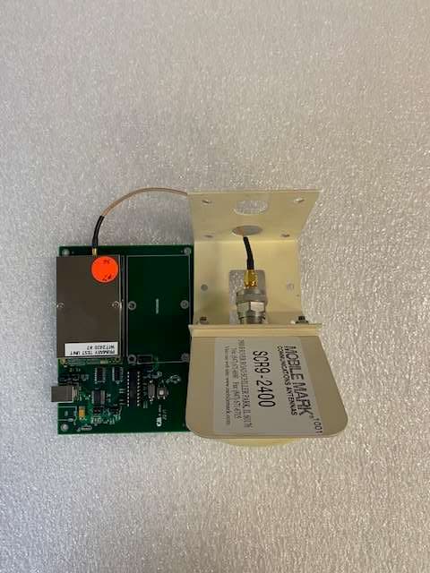
Click to zoom
Application Details
- Equipment Class
- DSS - Part 15 Spread Spectrum Transmitter
- Date of Grant
- Jul 12, 2021
- Application Purpose
- Original Equipment
- Date of Application
- Jul 12, 2021
- Equipment Note
- Wireless 2.4 GHz Industrial Transceiver
- Frequency Range
- 2401.69000000 - 2469.89000000
- Country
- United States
Documents & Files
Document Text
Text extracted from the exhibit documents filed with the FCC. Open a document above to read the original.
Users Manual
WIT2420 2.4GHz Spread Spectrum Wireless Industrial Transceiver Integration Guide June 2 nd 2021 Note: This unit has been tested and found to comply with the limits for a class A digital device, pursuant to part 15 of the FCC Rules. These limits are designed to provide reasonable protection against harmful interference when the equipment is operated in a commercial environment. This equipment generates, uses, and can radiate radio frequency energy and, if not installed and used in accordance with the instruction manual, may cause harmful interference to radio communications. Operation of this equipment in a residential area is likely to cause harmful interference in which case the user will be required to correct the interference at his own expense. The modular transmitter is only FCC authorized for the specific rule parts listed on the grant; when it is installed in a host device, the host product manufacturer is responsible for compliance to any other FCC rules that apply to the host not covered by the modular transmitter grant of certification. The final host product still requires Part 15 Subpart B compliance testing with the modular transmitter installed. If the WIT2420 is installed within another device the outside of the device into which the WIT2420 is installed must also display a label referring to the enclosed module. The label required for the WIT2420 module is as follows: Contains FCC ID: HSW-2420 and Contains IC: 4492A-2420. This device complies with Part 15 of the FCC Rules. Operation is subject to the following two (1) This device may not cause harmful interference, and (2) this device must accept any interference received, including inerference that may cause undesired operation. WARNING: changes not expressly approved by the party responsible for compliance could void the user’s authority to operate this device. WARNING: a 20cm separation distance must be maintained between this device and the user. This device complies with Industry Canada license-exempt RSS standard(s). Operation is subject to the following two conditions: (1) this device may not cause interference, and (2) this device must accept any interference, including interference that may cause undesired operation of the device. Le présent appareil est conforme aux CNR d'Industrie Canada applicables aux appareils radio exempts de licence. L'exploitation est autorisée aux deux conditions suivantes : (1) l'appareil ne doit pas produire de brouillage, et (2) l'utilisateur de l'appareil doit accepter tout brouillage radioélectrique subi, même si le brouillage est susceptible d'en compromettre le fonctionnement. About This Manual This manual is designed to allow integration of the Murata WIT2420 OEM module into complete products. Care has been taken to try and make sure all of the information in this manual is accurate. However, specifications can change over time and Murata cannot guarantee the accuracy of this information. If you have any questions on any information in this manual, please contact Murata Technical Support at (678) 684-2009. TABLE OF CONTENTS 1. INTRODUCTION ...................................................................................................................................................1 1.1 Why Spread Spectrum? ...................................................................................................................................1 1.2 Frequency Hopping vs. Direct Sequence ........................................................................................................2 2. RADIO OPERATION .............................................................................................................................................4 2.1. Synchronization and Registration ..................................................................................................................4 2.2. Data Transmission .........................................................................................................................................5 2.2.1. Point-to-Point .......................................................................................................................................5 2.2.2. Point-to-Multipoint ................................................................................................................................6 2.2.3. TDMA Mode .........................................................................................................................................6 2.2.4. Full Duplex Communication .................................................................................................................8 2.2.5. Error-free Packet Transmission Using ARQ ........................................................................................8 2.3. Modes of Operation ........................................................................................................................................9 2.3.1. Control and Data Modes ......................................................................................................................9 2.3.2. Sleep Mode ..........................................................................................................................................9 2.3.3. Low Power Mode and Duty Cycling .................................................................................................. 10 2.3.4. RF Flow Control Mode ....................................................................................................................... 10 3. PROTOCOL MODES ......................................................................................................................................... 11 3.1. Packet Formats ........................................................................................................................................... 13 3.1.1. Data Packet ......................................................................................................…
Text truncated - open the document above for the full version.
Cover Letter(s)
3505 Francis Circle Alpharetta, GA 30004 PH: 770-740-0717 www.ustech-lab.com Request for Confidentiality Date: July 1, 2021 Subject: Confidentiality Request for: FCC ID: HSW-2420, IC: 4462A-2420 Pursuant to FCC 47 CRF 0.457(d) and 0.459 and IC RSP-100, Section 12.4, the applicant requests that a part of the subject FCC/ISED application be held confidential. Type of Confidentiality Requested Exhibit Short Term Permanent Block Diagrams Short Term Permanent Operation Description/Theory of Operation Short Term Permanent Schematics Murata Electronics North America, Inc. has spent substantial effort in developing this product and it is one of the first of its kind in industry. Having the subject information easily available to "competition" would negate the advantage they have achieved by developing this product. Not protecting the details of the design will result in financial hardship. NOTE for ISED Applications: The applicant understands that until such time that ISED distinguishes between Short Term and Permanent Confidentiality, either type of marked exhibit above will simply be marked Confidential when submitted to ISED. Sincerely, By: __________________________ ___Sandi McEnery__- Agent (Signature/Title) (Print name)
Cover Letter(s)
3505 Francis Circle Alpharetta, GA 30004 PH: 770-740-0717 www.ustech-lab.com SDoC Attestation Letter Date: July 1, 2021 Subject: SDoC Attestation Letter: FCC ID: HSW-2420 The following equipment meets FCC Part 15 SDoC Requirements for digital device: Responsible Party: Murata Electronics North America 2200 Lake Park Drive Smyrna, GA 30080 Mark Tucker Manager, Hardware Engineering Group Equipment: Wireless 2.4 GHz Industrial Transceiver Model Name: WIT2420 Sincerely, By: __________________________ ___Sandi McEnery__- Agent (Signature/Title) (Print name)
Cover Letter(s)
AGENCY AGREEMENT Federal Communications Commission Date: 3/30/2021 P.O. Box 429 Columbia, MD 21045 Gentlemen: By signature below, we hereby appoint US Tech employees Sandi McEnery, Alan Ghasiani and George Yang to act as our agent with regard to all FCC equipment authorizations. This appointment will remain in effect until otherwise notified. I further certify by signature below that no party (per 47 CFR 1.2002(b)) to the application is subject to a denial of Federal benefits, including FCC benefits, pursuant to Section 5301 of the Anti-Drug Abuse Act of 1988, 21 U.S.C. 853(a). This appointment includes the authority to complete FCC Form 731 on our behalf and sign the application as an authorized agent. Name: Mark Tucker Signature: Title: HW Engineering Manager Date: 3/30/2021
Cover Letter(s)
July 1, 2021 TCB Applications Examiner RE: Modular Approval for Murata Electronics North America – FCC ID: HSW-2420 Dear Application Examiner: Regarding Part 15 Unlicensed Modular Transmitter Approval, the following requirements called out in FCC Public Notice DA 00-1407 are observed: 1) The modular transmitter must have its own RF shielding. This is intended to ensure that the module does not have to rely upon the shielding provided by the device into which it is installed in order for all modular transmitter emissions to comply with Part 15 limits. It is also intended to prevent coupling between the RF circuitry of the module and any wires or circuits in the device into which the module is installed. Such coupling may result in non-compliant operation. The Murata Electronics North America Model WIT2420 is a completely self contained radio which has its own RF shielding on the RF section. No other RF shielding is required or implemented. 2) The modular transmitter must have buffered modulation/data inputs (if such inputs are provided) to ensure that the module will comply with Part 15 requirements under conditions of excessive data rates or over-modulation. The Murata Electronics North America Model WIT2420 controls the data flow to the transmitter section compliant with Part 15 requirements. 3) The modular transmitter must have its own power supply regulation. This is intended to ensure that the module will comply with Part 15 requirements regardless of the design of the power supplying circuitry in the device into which the module is installed. The radio module has its own power regulator circuitry. 4) The modular transmitter must comply with the antenna requirements of Section 15.203 and 15.204(c). The antenna must either be permanently attached or employ a “unique” antenna coupler (at all connections between the module and the antenna, including the cable). Any antenna used with the module must be approved with the module, either at the time of initial authorization or through a Class II permissive change. The “professional installation” provision of Section 15.203 may not be applied to modules. For this application, the Murata Electronics North America Model WIT2420 employs antennas with unique connectors as described in the certification test report and User/Integrators Manual. 5) The modular transmitter must be tested in a stand-alone configuration, i.e., the module must not be inside another device during testing. This is intended to demonstrate that the module is capable of complying with Part 15 emission limits regardless of the device into which it is eventually installed. Unless the transmitter module will be battery powered, it must comply with the AC line conducted requirements found in Section 15.207. AC or DC power lines and data input/output lines connected to the module must not contain ferrites, unless they will be marketed with the module (see Section 15.27(a)). The length of these lines shall be length typical of actual use or, if that length is unknown, at least 10 centimeters to insure that there is no coupling between the case of the module and supporting equipment. Any accessories, peripherals, or support equipment connected to the module during testing shall be unmodified or commercially available (see Section 15.31(i)). The module itself was tested while connected to a Host Board. The Host Board was provided as a means to communicate with the radio through the serial connection. Nothing on the Host Board contributes to the performance of the radio, therefore the radio is considered to have been tested in a standalone configuration. 6) The modular transmitter must be labeled with its own FCC ID number, and, if the FCC ID is not visible when the module is installed inside another device, then the outside of the device into which the module is installed must also display a label referring to the enclosed module. This exterior label can use wording such as the following: “Contains Transmitter Module FCC ID: XYZMODEL1” or “Contains FCC ID: XYZMODEL1.” Any similar wording that expresses the same meaning may be used. The Grantee may either provide such a label, an example of which must be included in the application for equipment authorization, or, must provide adequate instructions along with the module which explain this requirement. In the latter case, a copy of these instructions must be included in the application for equipment authorization. The Murata Electronics North America Model WIT2420 shall bear a label with the FCC ID on the front of the module. The FCC ID shall be visible when installed on the host device. The Host device will bear a label calling out the FCC ID using a statement similar to the following: “Contains FCC ID: HSW-2420”. 7) The modular transmitter must comply with any specific rule or operating requirements applicable to the transmitter and the manufacturer must provide adequate instructions along with the module to explain any such requirements. A copy of these instructions must be included in the application for equipment authorization. For example, there are very strict operational and timing requirements that must be met before a transmitter is authorized for operation under Section 15.231. For instance, data transmission is prohibited, except for operation under Section 15.231(e), in which case there are separate field strength level and timing requirements. Compliance with these requirements must be assured. The Murata Electronics North America Model WIT2420 comes equipped with embedded firmware that controls these parameters. 8) The modular transmitter must comply with any applicable RF exposure requirements. For example, FCC Rules in Sections 2.1091, 2.1093 and specific Sections of Part 15, including 15.319(i), 15.407(f), 15.253(f) and 15.255(g), require that Unlicensed PCS, UNII and millimeter wave devices perform routine environmental evaluation for RF Exposure to demonstrate compliance. In addition, spread spectrum transmitters …
Text truncated - open the document above for the full version.
External Photos
US Tech Test Report: FCC Part 15 Certification/ RSS 247 FCC ID: HSW-2420 IC: 4492A-2420 Test Report Number: 21-0174 Issue Date: July 1, 2021 Customer: Murata Electronics North America Model: WIT2420 Page 1 of 14 EXTERNAL PHOTOGRAPHS Figure 1. Top of EUT US Tech Test Report: FCC Part 15 Certification/ RSS 247 FCC ID: HSW-2420 IC: 4492A-2420 Test Report Number: 21-0174 Issue Date: July 1, 2021 Customer: Murata Electronics North America Model: WIT2420 Page 2 of 14 Figure 2. Bottom of EUT US Tech Test Report: FCC Part 15 Certification/ RSS 247 FCC ID: HSW-2420 IC: 4492A-2420 Test Report Number: 21-0174 Issue Date: July 1, 2021 Customer: Murata Electronics North America Model: WIT2420 Page 3 of 14 Figure 3. Left Side of EUT US Tech Test Report: FCC Part 15 Certification/ RSS 247 FCC ID: HSW-2420 IC: 4492A-2420 Test Report Number: 21-0174 Issue Date: July 1, 2021 Customer: Murata Electronics North America Model: WIT2420 Page 4 of 14 Figure 4. Right Side of EUT US Tech Test Report: FCC Part 15 Certification/ RSS 247 FCC ID: HSW-2420 IC: 4492A-2420 Test Report Number: 21-0174 Issue Date: July 1, 2021 Customer: Murata Electronics North America Model: WIT2420 Page 5 of 14 Figure 5. Front of EUT US Tech Test Report: FCC Part 15 Certification/ RSS 247 FCC ID: HSW-2420 IC: 4492A-2420 Test Report Number: 21-0174 Issue Date: July 1, 2021 Customer: Murata Electronics North America Model: WIT2420 Page 6 of 14 Figure 6. Back of EUT US Tech Test Report: FCC Part 15 Certification/ RSS 247 FCC ID: HSW-2420 IC: 4492A-2420 Test Report Number: 21-0174 Issue Date: July 1, 2021 Customer: Murata Electronics North America Model: WIT2420 Page 7 of 14 Figure 7. EUT with Radio Module Removed US Tech Test Report: FCC Part 15 Certification/ RSS 247 FCC ID: HSW-2420 IC: 4492A-2420 Test Report Number: 21-0174 Issue Date: July 1, 2021 Customer: Murata Electronics North America Model: WIT2420 Page 8 of 14 Figure 8. Back of Radio Module Removed from PCB US Tech Test Report: FCC Part 15 Certification/ RSS 247 FCC ID: HSW-2420 IC: 4492A-2420 Test Report Number: 21-0174 Issue Date: July 1, 2021 Customer: Murata Electronics North America Model: WIT2420 Page 9 of 14 Figure 9. Corner Reflector Antenna for Murata WIT2420 Manufacturer Type Gain Connector Mobilemark Corner Reflector +9.0 Reverse N-Type US Tech Test Report: FCC Part 15 Certification/ RSS 247 FCC ID: HSW-2420 IC: 4492A-2420 Test Report Number: 21-0174 Issue Date: July 1, 2021 Customer: Murata Electronics North America Model: WIT2420 Page 10 of 14 Figure 10. Corner Reflector Antenna on EUT US Tech Test Report: FCC Part 15 Certification/ RSS 247 FCC ID: HSW-2420 IC: 4492A-2420 Test Report Number: 21-0174 Issue Date: July 1, 2021 Customer: Murata Electronics North America Model: WIT2420 Page 11 of 14 Figure 11. Patch Antenna for Murata WIT2420 Manufacturer Type Gain Connector Murata Patch +6.0 MMCX US Tech Test Report: FCC Part 15 Certification/ RSS 247 FCC ID: HSW-2420 IC: 4492A-2420 Test Report Number: 21-0174 Issue Date: July 1, 2021 Customer: Murata Electronics North America Model: WIT2420 Page 12 of 14 Figure 12. Patch Antenna on EUT US Tech Test Report: FCC Part 15 Certification/ RSS 247 FCC ID: HSW-2420 IC: 4492A-2420 Test Report Number: 21-0174 Issue Date: July 1, 2021 Customer: Murata Electronics North America Model: WIT2420 Page 13 of 14 Figure 13. Dipole Antenna for Murata WIT2420 Manufacturer Type Gain Connector Nearson Dipole +2.0 Reverse SMA US Tech Test Report: FCC Part 15 Certification/ RSS 247 FCC ID: HSW-2420 IC: 4492A-2420 Test Report Number: 21-0174 Issue Date: July 1, 2021 Customer: Murata Electronics North America Model: WIT2420 Page 14 of 14 Figure 14. Dipole Antenna on EUT
Internal Photos
US Tech Test Report: FCC Part 15 Certification/ RSS 247 FCC ID: HSW-2420 IC: 4462A-2420 Test Report Number: 21-0174 Issue Date: July 1, 2021 Customer: Murata Electronics North America Model: WIT2420 Page 1 of 2 INTERNAL PHOTOGRAPHS Figure 1. Radio with Shield Removed – Top US Tech Test Report: FCC Part 15 Certification/ RSS 247 FCC ID: HSW-2420 IC: 4462A-2420 Test Report Number: 21-0174 Issue Date: July 1, 2021 Customer: Murata Electronics North America Model: WIT2420 Page 2 of 2 Figure 2. Radio with Shield Removed - Bottom
RF Exposure Info
US Tech Test Report: FCC Part 15 Certification/ RSS 247 FCC ID: HSW-2420 IC: 4492A-2420 Report Number: 21-0174 Issue Date: July 1, 2021 Customer: Murata Electronics North America Models: WIT2420 Page 1 of 2 Maximum Permissible Exposure to RF (MPE) CFR 15.247 (i), CFR 1.1310 (e) The maximum exposure level to the public from the RF power of the EUT shall not exceed a power density, S as per the respective limits in Table 1 below, at a distance, d, of 20 cm (Mobile condition) from the EUT. TABLE 1—LIMITS FOR MAXIMUM PERMISSIBLE EXPOSURE (MPE) Frequency range (MHz) Electric field strength (V/m) Magnetic field strength (A/m) Power density (mW/cm 2 ) Averaging time (minutes) Limits for General Population/Uncontrolled Exposure 0.3-1.34 614 1.63 *100 30 1.34-30 824/f 2.19/f *180/f 2 30 30-300 27.5 0.073 0.2 30 300-1,500 f/1500 30 1,500-100,000 1.0 30 f = frequency in MHz * = Plane-wave equivalent power density Therefore, for: MPE for 2400-2483.5 MHz: Limit: 1.0 mW/cm 2 Peak Power (dBm) = 17.23 dBm Peak Power (Watts) = 0.053 W Gain of Transmit Antenna = 9.0 dB i = 7.9 numeric (max gain antenna) d = Distance = 20 cm = 0.2 m S = (PG/ 4d 2 ) = EIRP/4A = 0.053 (7.9)/4*π*0.2*0.2 = 0.4187/0.5030 = 0.8324 W/m 2 = (0.8324 W/m 2 ) (1m 2 /W) (0.1 mW/cm 2 ) = 0.08324 mW/cm 2 which is << less than S = 1.0 mW/cm 2 US Tech Test Report: FCC Part 15 Certification/ RSS 247 FCC ID: HSW-2420 IC: 4492A-2420 Report Number: 21-0174 Issue Date: July 1, 2021 Customer: Murata Electronics North America Models: WIT2420 Page 2 of 2 RSS-102, 2.5.2 compliance for 2400 MHz – 2483.5 MHz for the Murata model: WIT2420: At or above 300 MHz and below 6 GHz and the source-based, time-averaged maximum e.i.r.p. of the device is equal to or less than 1.31 x 10 -2 ƒ 0.6834 W (adjusted for tune-up tolerance), where ƒ is in MHz; In this case ƒ = 2440 MHz 1.31 * 10 -2 * 2440 0.6834 = 2.7 W EUT max EIRP = 17.23 dBm + (9.0 dBi) = 26.23 dBm EIRP = 0.420 W Which is << than 2.7 W All calculations performed by: Date: July 1, 2021 Test Engineer: George Yang Signature:____________________
Test Report
Page 1 of 64 CERTIFICATION TEST REPORT FCC Part 2, Subpart J, Paragraph 2.907 Equipment Authorization of Certification for an Intentional Radiator per Part 15, Subpart C, paragraphs 15.207, 15.209 and 15.247 & RSS-247 Issue 2: Digital Transmission Systems (DTSs), Frequency Hopping Systems (FHSs) and License-Exempt Local Area Network (LE-LAN) Devices Equipment under test: WIT2420 Model: WIT2420 Company Name: Murata Electronics North America, Inc. FCC ID: HSW-2420 IC: 4492A-2420 Date of Test(s): May 18 - 28, 2021 June 1 - 29, 2021 Date of Issue: July 1, 2021 UST Project Number: 21-0174 Total Pages: 64 Test report completed by: Test report approval by: Name Mark Afroozi Name George Yang Title Test Engineer Title Technical Manager 3505 Francis Circle Alpharetta, GA 30004 PH: 770-740-0717 Fax: 770-740-1508 www.ustech-lab.com Page 2 of 64 I certify that I am authorized to sign for the Test Agency and that all of the statements in this report and in the Exhibits attached hereto are true and correct to the best of my knowledge and belief: US TECH (Agent Responsible For Test): By: Alan Ghasiani Name: Title: Compliance Engineer – President Date: July 1, 2021 This report shall not be reproduced except in full. This report may be copied in part only with the prior written approval of US Tech. The results contained in this report are subject to the adequacy and representative character of the sample provided. This report must not be used to claim product certification, approval, or endorsement by NVLAP, NIST or any agency of the Federal Government. 3505 Francis Circle Alpharetta, GA 30004 PH : 770-740-0717 Fax : 770-740-1508 www.ustech-lab.com US Tech Test Report: FCC Part 15 Certification / RSS-247 FCC ID: HSW-2420 IC: 4492A-2420 Test Report Number: 21-0174 Issue Date: July 1, 2021 Customer: Murata Electronics North America, Inc. Model: WIT2420 Page 3 of 64 MEASUREMENT TECHNICAL REPORT Company Name: Murata Electronics North America, Inc. Address: 2200 Lake Park Drive Smyrna, GA 30080-7604 Model: WIT2420 FCC ID: HSW-2420 IC: 4492A-2420 Date: July 1, 2021 This report concerns (check one): ☒ Original ☐ Class II Permissive Change Equipment type: 2.4 GHz ISM Radio Transceiver Technical Information: Radio Technology: FHSS Frequency of Operation (MHz): 2401.6896 – 2469.888 Rated Output Power (dBm): 17 – 18 Type of Modulation: GFSK Data/Bit Rate (kbps): 460 Number of Channels: 75 Antenna Gain (dBi): Refer to Tables 5 and 6 Software used to program EUT: WinCom 3.11 EUT firmware: WIT2420 v5.59 Measured Power Level: 17.23 dBm Report prepared by: US Tech 3505 Francis Circle Alpharetta, GA 30004 PH : 770-740-0717 Fax : 770-740-1508 www.ustech-lab.com US Tech Test Report: FCC Part 15 Certification / RSS-247 FCC ID: HSW-2420 IC: 4492A-2420 Test Report Number: 21-0174 Issue Date: July 1, 2021 Customer: Murata Electronics North America, Inc. Model: WIT2420 Page 4 of 64 Table of Contents Page 1 General Information ............................................................................................... 8 1.1 Purpose of this Report ....................................................................................... 8 1.2 Characterization of Test Sample ........................................................................ 8 1.3 Product Description ............................................................................................ 8 1.4 Configuration of Tested System ......................................................................... 8 1.5 Test Facility ........................................................................................................ 9 1.6 Related Submittal(s)/Grant(s)............................................................................. 9 2 Tests and Measurements ..................................................................................... 12 2.1 Test Equipment ................................................................................................ 12 2.2 Modifications to EUT Hardware ........................................................................ 12 2.3 Number of Measurements for Intentional Radiators (CFR 15.31(m)) ............... 13 2.4 Frequency Range of Radiated Measurements (CFR 15.33) ............................ 13 2.4.1 Intentional Radiator ....................................................................................... 13 2.4.2 Unintentional Radiator ................................................................................... 13 2.5 Measurement Detector Function and Bandwidth (CFR 15.35) ......................... 14 2.5.1 Detector Function and Associated Bandwidth ............................................... 14 2.5.2 Corresponding Peak and Average Requirements ......................................... 14 2.5.3 Pulsed Transmitter Averaging ....................................................................... 14 2.6 Transmitter Duty Cycle (Part 15.35(c)) ............................................................. 15 2.7 Restricted Bands of Operation (Part 15.205) ................................................... 16 2.8 EUT Antenna Requirements (CFR 15.203) ...................................................... 16 2.9 Maximum Peak Conducted Output Power (CFR 15.247(b)(3)) ........................ 17 2.10 Antenna Conducted Intentional and Spurious Emissions (CFR 15.209, 15.247(d)) (RSS-247 (5.5), RSS-Gen 8.9) ................................................................. 21 2.11 Intentional Radiator, Radiated Emissions (CFR 15.209, 15.247(d)) ............. 30 2.12 Band Edge Measurements – (CFR 15.247(d)) ............................................. 46 2.13 20 dB and 99% Occupied Bandwidth (RSS-Gen, 6.7 and RSS-247, 5.1 (b)) 51 2.14 Channel Carrier Frequency Separation (CFR 15.247 (1), RSS-247 5.1(b)) .. 55 2.15 Hopping Channels and Time of Occupancy (CFR 15.247 (1)(iii), RSS-247 5.1(d)) 56 2.16 Intentional Radiator Power Line Conducted Emissions (CFR 15.207) .......... 61 2.17 Radiated Emissions of the Int…
Text truncated - open the document above for the full version.
Test Setup Photos
US Tech Test Report: FCC Part 15 Certification/ RSS 247 FCC ID: HSW-2420 IC: 4492A-2420 Test Report Number: 21-0174 Issue Date: July 1, 2021 Customer: Murata Electronics North America Model: WIT2420 Page 1 of 10 TEST CONFIGURATION PHOTOGRAPHS Figure 1. Radiated Emissions, EUT Worst Case Position Test Setup: EUT with Corner Reflector Antenna US Tech Test Report: FCC Part 15 Certification/ RSS 247 FCC ID: HSW-2420 IC: 4492A-2420 Test Report Number: 21-0174 Issue Date: July 1, 2021 Customer: Murata Electronics North America Model: WIT2420 Page 2 of 10 Figure 2. . Radiated Emissions, 1 GHz to 25 GHz Test Setup: EUT with Corner Reflector Antenna US Tech Test Report: FCC Part 15 Certification/ RSS 247 FCC ID: HSW-2420 IC: 4492A-2420 Test Report Number: 21-0174 Issue Date: July 1, 2021 Customer: Murata Electronics North America Model: WIT2420 Page 3 of 10 Figure 3. Radiated Emissions, EUT Worst Case Position Test Setup: EUT with Dipole Antenna US Tech Test Report: FCC Part 15 Certification/ RSS 247 FCC ID: HSW-2420 IC: 4492A-2420 Test Report Number: 21-0174 Issue Date: July 1, 2021 Customer: Murata Electronics North America Model: WIT2420 Page 4 of 10 Figure 4. Radiated Emissions, 1 GHz to 25 GHz Test Setup: EUT with Dipole Antenna US Tech Test Report: FCC Part 15 Certification/ RSS 247 FCC ID: HSW-2420 IC: 4492A-2420 Test Report Number: 21-0174 Issue Date: July 1, 2021 Customer: Murata Electronics North America Model: WIT2420 Page 5 of 10 Figure 5. Radiated Emissions EUT Worst Case Position Test Setup: EUT with Patch Antenna US Tech Test Report: FCC Part 15 Certification/ RSS 247 FCC ID: HSW-2420 IC: 4492A-2420 Test Report Number: 21-0174 Issue Date: July 1, 2021 Customer: Murata Electronics North America Model: WIT2420 Page 6 of 10 Figure 6. Radiated Emissions, 1 GHz to 25 GHz Test Setup: EUT with Patch Antenna US Tech Test Report: FCC Part 15 Certification/ RSS 247 FCC ID: HSW-2420 IC: 4492A-2420 Test Report Number: 21-0174 Issue Date: July 1, 2021 Customer: Murata Electronics North America Model: WIT2420 Page 7 of 10 Figure 7. Radiated Spurious Emissions: EUT Worst Case Position Test Setup US Tech Test Report: FCC Part 15 Certification/ RSS 247 FCC ID: HSW-2420 IC: 4492A-2420 Test Report Number: 21-0174 Issue Date: July 1, 2021 Customer: Murata Electronics North America Model: WIT2420 Page 8 of 10 Figure 8. Radiated Spurious Emissions: 9 kHz to 30 MHz US Tech Test Report: FCC Part 15 Certification/ RSS 247 FCC ID: HSW-2420 IC: 4492A-2420 Test Report Number: 21-0174 Issue Date: July 1, 2021 Customer: Murata Electronics North America Model: WIT2420 Page 9 of 10 Figure 9. Radiated Spurious Emissions: 30 MHz to 200 MHz US Tech Test Report: FCC Part 15 Certification/ RSS 247 FCC ID: HSW-2420 IC: 4492A-2420 Test Report Number: 21-0174 Issue Date: July 1, 2021 Customer: Murata Electronics North America Model: WIT2420 Page 10 of 10 Figure 10. Radiated Spurious Emissions: 200 MHz to 1 GHz
Contact Information
Applicant
Mark Tucker(Director of Hardware Engineering)
Test Firm
US TechGeorge Yang
Technical Specifications
| # | Rule Parts | Frequency Range | Power Output |
|---|---|---|---|
| 1 | 15C | 2.40 GHz - 2.47 GHz | 53.00 mW |
Other Applications from Murata Electronics North America
HSW2NR
May 13, 2026LBMA0ZZ2NR
Equipment Class
DTS - Digital Transmission SystemHSW2FR
Aug 29, 2024Communication Module
Equipment Class
DTS - Digital Transmission System
HSW2EG
Dec 14, 2022Type 2EG BLE Module
Equipment Class
DTS - Digital Transmission System
HSW-608B
Apr 11, 2021Wireless Medical Telemetry Service Radio Module
Equipment Class
TNB - Licensed Non-Broadcast Station Transmitter
HSW-TY1SCDM
Feb 12, 2020Communication Module
Equipment Class
PCB - PCS Licensed Transmitter