HSW-2410PMODULAR 2.4 GHZ TRANSCEIVER
Murata Electronics North America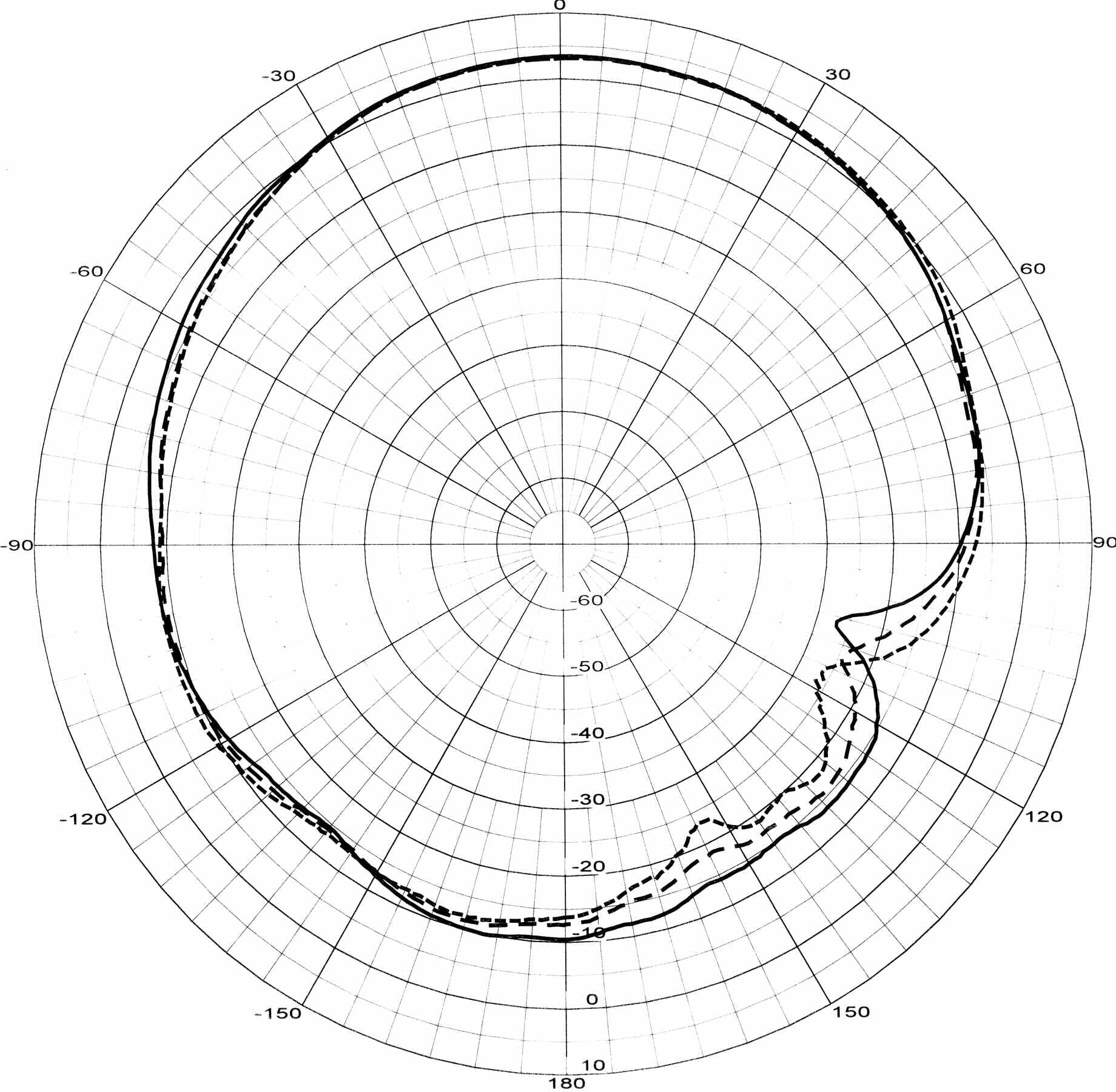
Click to zoom
Application Details
- Equipment Class
- DSS - Part 15 Spread Spectrum Transmitter
- Date of Grant
- Jan 28, 2008
- Application Purpose
- Original Equipment
- Date of Application
- Jan 28, 2008
- Equipment Note
- MODULAR 2.4 GHZ TRANSCEIVER
- Frequency Range
- 2401.68960000 - 2469.88800000
- Country
- United States
Documents & Files
Document Text
Text extracted from the exhibit documents filed with the FCC. Open a document above to read the original.
Users Manual
5015 B.U. Bowman Drive Buford, GA 30518 USA Voice: 770-831-8048 Fax: 770-831-8598 Certification Exhibit FCC ID: HSW-2410P IC: 4492A-2410P FCC Rule Part: 15.247 IC Radio Standards Specification: RSS-210 ACS Report Number: 08-0020 - 15C Manufacturer: Cirronet Model: WIT2410P Installation Guide WIT2410P For Portable Operation 2.4GHz Spread Spectrum Wireless Industrial Transceiver Integration Guide 3079 Premiere Pkwy Ste 140 Duluth, Georgia 30097 www.cirronet.com +1 (678) 684-2000 Important Regulatory Information Cirronet Product FCC ID: HSW-2410P IC 4492A-2410P FCC MPE Requirements The WIT2410P is designed for portable applications as a remote unit. These remote radios are installed in belt packs or other close to the body devices worn by the user. The power output, duty cycle and antenna gain are set to be well below the FCC’s Maximum Permissible Exposure to radio frequency energy. See Appendix I, II and III Page 54 and 55. The antenna(s) used for this transmitter must not be co-located or operating in conjunction with any other antenna or transmitter. The integrator of the WIT2410P must place on the outside of their final device. “Contains FCC ID: HSW-2410P” Note: This unit has been tested and found to comply with the limits for a Class B digital device, pursuant to part 15 of the FCC Rules. These limits are designed to provide reasonable protection against harmful interference when the equipment is operated in a commercial environment. This equipment generates, uses, and can radiate radio frequency energy and, if not installed and used in accordance with the instruction manual, may cause harmful interference to radio communications. Operation of this equipment in a residential area is likely to cause harmful interference in which case the user will be required to correct the interference at their expense. Declaration of Conformity Warning! The RLAN transceiver within this device uses a band of frequencies that are not completely harmonized within the European Community. Before using, please read the European Operation Section of the Products User’s Guide for limitations. The WIT2410 to which this declaration relates is in conformity with the essential requirements of the R&TTE directive 1999/5/EC and complies with the following standards and/or other normative documents: EN 300 328 Use Within the European Union The WIT2410P is intended for use within the European Community States and in the following non-European Union States: Norway & Switzerland Use of the WIT2410 in France When used in France, the WIT2410 can only be operated with the France hopping pattern selected. This is accomplished by setting the pe parameter to 1. Refer to European Union Settings in this manual for details. Canadian Department of Communications Industry Canada (IC) Notice Canadian Department of Communications Industry Canada (IC) Notice This apparatus complies with Health Canada’s Safety Code 6 / IC RSS 102. "To prevent radio interference to the licensed service, this device is intended to be operated indoors and away from windows to provide maximum shielding. Equipment (or its transmit antenna) that is installed outdoors may be subject to licensing." ICES-003 This digital apparatus does not exceed the Class B limits for radio noise emissions from digital apparatus as set out in the radio interference regulations of Industry Canada. Le présent appareil numérique n'émet pas de bruits radioélectriques dépassant les limites applicables aux appareils numériques de Classe B prescrites dans le règlement sur le brouillage radioélectrique édicté par Industrie Canada. NOTE! Any changes of modifications not expressly approved by the party responsible for compliance could void the user’s authority operate the equipment. TABLE OF CONTENTS 1. INTRODUCTION ......................................................................................................................1 1.1. Why Spread Spectrum? ........................................................................................................1 1.2. Frequency Hopping vs. Direct Sequence..............................................................................2 2. RADIO OPERATION ................................................................................................................5 2.1. Synchronization and Registration ........................................................................................5 2.2. Data Transmission ...............................................................................................................6 2.2.1. Point-to-Point .............................................................................................................6 2.2.2. Point-to-Multipoint ....................................................................................................7 2.2.3. Handle Assignment ....................................................................................................7 2.2.4. TDMA Operation .......................................................................................................8 2.2.5. Full Duplex Communication....................................................................................10 2.2.6. Error-free Packet Transmission Using ARQ............................................................10 2.3. Modes of Operation ...........................................................................................................11 2.3.1. Control and Data Modes ..........................................................................................11 2.3.2. Sleep Mode ..............................................................................................................11 2.3.3. Low Power Mode and Duty Cycling .......................................................................12 2.3.4. RF Flow Control Mode ............................................................................................12 2.3.5. Co-Existing with 802.11b Networks...............................…
Text truncated - open the document above for the full version.
Cover Letter(s)
Federal Communications Commission Date: January 17, 2008 P.O. Box 429 Columbia, MD 21045 Gentlemen: I hereby appoint Kirby Munroe at Advanced Compliance Solutions, Inc. to act as our agent in the preparation of an application for equipment authorization of model WIT2410P to the FCC Rules and Regulations. I certify that all exhibits contained within this filing properly describe the device or system for which authorization is sought. I further certify that appropriate arrangements have been made to assure that production units of this equipment bearing the name and FCC IDENTIFIER listed in this application will continue to comply with the Commission's requirements. I further certify by signature below that no party (per 47 CFR 1.2002(b)) to the application is subject to a denial of Federal benefits, including FCC benefits, pursuant to Section 5301 of the Anti-Drug Abuse Act of 1988, 21 U.S.C. 853(a). This appointment also includes the authority to complete FCC Form 731 on our behalf and sign the application as an authorized agent. Sincerely, Mark Tucker V.P of Engineering Date: January 17, 2008
Cover Letter(s)
CONFIDENTIALITY REQUEST Federal Communications Commission Date: January 17, 2008 Equipment Authorization Branch 7435 Oakland Mills Road Columbia, MD 21046 Gentlemen: Cirronet respectfully requests confidentiality of certain materials provided with the submission of the WIT2410P under FCC ID: HSW-2410P in accordance with FCC Regulations 0.459. The confidentiality request applies to the schematics, bill of materials and block diagrams contained in this filing and included in the following files. 08-0020 – Schematics.pdf 08-0020 – Parts List.pdf 08-0020 – System Block Diagram.pdf The WIT2410P has been developed at considerable effort and expense by Cirronet. These items are considered as Trade Secrets and therefore public access to the proprietary material could possible result in duplication of equipment that could severely damage the company's business advantage. I appreciate your assistance in this matter. Sincerely, Mark Tucker V.P. of Engineering Date: January 17, 2008
Cover Letter(s)
Advanced Compliance Solutions – 5015 B.U. Bowman Drive, Buford, GA 30518 Phone: (770) 831-8048 Fax: (770) 831-8598 January 21, 2008 Timco Engineering Inc. 849 N.W. State Road 45 P.O. Box 370 Newberry, Florida 32669 FCC ID: HSW-2410P Dear Sir: The following application is submitted on behalf of our client, Cirronet, Inc., for evaluation of model WIT2410P for Certification in accordance with Part 2 of the FCC rules. This device is submitted for modular approval in accordance with FCC Public Notice DA 00-1407. The WIT2410P module is host independent and utilized in portable RF exposure conditions. Information contained in this filing will show the source-based time-averaged RF output power is below the lower threshold for TCB SAR therefore SAR data is not provided. If you have any questions regarding this application, please contact me. Sincerely, Kirby Munroe Director, Wireless Certifications
Cover Letter(s)
Tuesday, January 18, 2008 Dear Application Examiner Regarding Part 15 Unlicensed Modular Transmitter Approval, the following requirements called out in FCC Public Notice DA 00-1407 are observed: 1. The WIT2410P has its own RF shielding. 2. The WIT2410P modular transmitter has buffered modulation/data inputs to ensure that the module will comply with Part 15 requirements under conditions of excessive data rates or over- modulation. 3. The WIT2410P employs on board power supply regulation. 4. The WIT2410P employs a MMCX connector. Professional installation is required. 5. The WIT2410P was tested in a stand-alone configuration. 6. The WIT2410P has a label with the FCC ID: HSW-2410P 7. The WIT2410P complies with FCC DTS for Frequency Hopping Spread Spectrum Operation. An Integration Guide is provided for every module sold. This guide instructs the user in the proper operation of the device. The text in the guide specifies FCC Part 15 compliance: Al Patrick Sr. Compliance Engineer Cirronet Inc. [email protected]
External Photos
5015 B.U. Bowman Drive Buford, GA 30518 USA Voice: 770-831-8048 Fax: 770-831-8598 Certification Exhibit FCC ID: HSW-2410P IC: 4492A-2410P FCC Rule Part: 15.247 IC Radio Standards Specification: RSS-210 ACS Report Number: 08-0020 - 15C Manufacturer: Cirronet Model: WIT2410P External Photos Model(s): WIT2410P FCC ID: HSW-2410P IC: 4492A-2410P ACS Report: 08-0020 Advanced Compliance Solutions Page 2 Figure 1: External Front Model(s): WIT2410P FCC ID: HSW-2410P IC: 4492A-2410P ACS Report: 08-0020 Advanced Compliance Solutions Page 3 Figure 2: External Back ACE-2400-NF Antenna FREQUENCY RANGE 2.4 ~ 2.5 GHz IMPEDANCE (NOMINAL) 50 Ω V.S.W.R. 1.9 : 1 (max.) GAIN 2 dBi (min.) ± 1dB (max.) RADIATION PATTERN OMNI-DIRECTIONAL POLARIZATION VERTICAL LENGTH 124.0± 2.0mm PULLING STRENGTH 3 kgf (min.) SWIVEL TORQUE 3 kgf (min.) TEMPERATURE −30 ~ +60 °C CONNECTOR SMA-MALE Reverse PA2400/PA2410 Patch Antennas OOmmnnii DDiirreeccttiioonnaall GGaaiinn AAnntteennnnaass S S p p e e c c i i f f i i c c a a t t i i o o n n s s M M o o d d e e l l # # P P A A 2 2 4 4 0 0 0 0 M M o o d d e e l l # # P P A A 2 2 4 4 1 1 0 0 Frequency Bandwidth2.4 - 2.5 GHz2.4 - 2.5 GHz Antenna TypePatchPatch Gain6dBi2dBi V. S. W. R.<1.9:1<1.9:1 Nominal Impedance50 Ohms50 Ohms Radiation PatternDirectionalDirectional PolarizationLinearLinear ConnectorHuber-Suhner Type 81 MMCX-50-0-1 PlugHuber-Suhner Type 81 MMCX-50-0-1 Plug CIRRONET TM 3079 Premiere pk wy, Suite 140, Duluth, georgia 30097 www.cirronet.com p: +1 678 684 2000 f: +1 678 684 2001 1.47 [37.2] 1.85 [46.9] 2.40 [60.8] .19 [4.8] .27 [6.9] .60 [15.1] .10 [2.5] 1. CONNECTOR IS HUBER-SUHNER TYPE 81 MMCX-50-0-1 (PLUG) OR EQUIVALENT. R .062 (6 PLACES) 1. CONNECTOR IS HUBER-SUHNER TYPE 81 MMCX-50-0-1 (PLUG) OR EQUIVALENT. 1.82 .21 .335 .135 .21.21 .74 E Plane PA2410 Plots H Plane E Plane PA2400 Plots H Plane PA2400 PA2410
ID Label/Location Info
5015 B.U. Bowman Drive Buford, GA 30518 USA Voice: 770-831-8048 Fax: 770-831-8598 Certification Exhibit FCC ID: HSW-2410P IC: 4492A-2410P FCC Rule Part: 15.247 IC Radio Standards Specification: RSS-210 ACS Report Number: 08-0020 - 15C Manufacturer: Cirronet Model: WIT2410P Label Information
Internal Photos
5015 B.U. Bowman Drive Buford, GA 30518 USA Voice: 770-831-8048 Fax: 770-831-8598 Certification Exhibit FCC ID: HSW-2410P IC: 4492A-2410P FCC Rule Part: 15.247 IC Radio Standards Specification: RSS-210 ACS Report Number: 08-0020 - 15C Manufacturer: Cirronet Model: WIT2410P Internal Photos Model(s): WIT2410P FCC ID: HSW-2410P IC: 4492A-2410P ACS Report: 08-0020 Advanced Compliance Solutions Page 2 Figure 1: PCB with Shields - Front Model(s): WIT2410P FCC ID: HSW-2410P IC: 4492A-2410P ACS Report: 08-0020 Advanced Compliance Solutions Page 3 Figure 2: PCB without Shields - Front Model(s): WIT2410P FCC ID: HSW-2410P IC: 4492A-2410P ACS Report: 08-0020 Advanced Compliance Solutions Page 4 Figure 3: PCB - Back
Operational Description
5015 B.U. Bowman Drive Buford, GA 30518 USA Voice: 770-831-8048 Fax: 770-831-8598 Certification Exhibit FCC ID: HSW-2410P IC: 4492A-2410P FCC Rule Part: 15.247 IC Radio Standards Specification: RSS-210 ACS Report Number: 08-0020 - 15C Manufacturer: Cirronet Model: WIT2410P Theory of Operation WIT2410P 2.4GHz Spread Spectrum Wireless Industrial Transceiver Integration Guide 3079 Premiere Pkwy Ste 140 Duluth, Georgia 30097 www.cirronet.com +1 (678) 684-2000 Important Regulatory Information Cirronet Product FCC ID: HSW-2410P IC 4492A-2410P FCC MPE Requirements The WIT2410P is designed for portable applications as a remote unit. These remote radios are installed in belt packs or other close to the body devices worn by the user. The power output, duty cycle and antenna gain are set to be well below the FCC’s Maximum Permissible Exposure to radio frequency energy. See Appendix I, II and III Page 54 and 55. Note: This unit has been tested and found to comply with the limits for a Class B digital device, pursuant to part 15 of the FCC Rules. These limits are designed to provide reasonable protection against harmful interference when the equipment is operated in a commercial environment. This equipment generates, uses, and can radiate radio frequency energy and, if not installed and used in accordance with the instruction manual, may cause harmful interference to radio communications. Operation of this equipment in a residential area is likely to cause harmful interference in which case the user will be required to correct the interference at their expense. Declaration of Conformity Warning! The RLAN transceiver within this device uses a band of frequencies that are not completely harmonized within the European Community. Before using, please read the European Operation Section of the Products User’s Guide for limitations. The WIT2410 to which this declaration relates is in conformity with the essential requirements of the R&TTE directive 1999/5/EC and complies with the following standards and/or other normative documents: EN 300 328 Use Within the European Union The WIT2410P is intended for use within the European Community States and in the following non-European Union States: Norway & Switzerland Use of the WIT2410 in France When used in France, the WIT2410 can only be operated with the France hopping pattern selected. This is accomplished by setting the pe parameter to 1. Refer to European Union Settings in this manual for details. Canadian Department of Communications Industry Canada (IC) Notice Canadian Department of Communications Industry Canada (IC) Notice This apparatus complies with Health Canada’s Safety Code 6 / IC RSS 102. "To prevent radio interference to the licensed service, this device is intended to be operated indoors and away from windows to provide maximum shielding. Equipment (or its transmit antenna) that is installed outdoors may be subject to licensing." ICES-003 This digital apparatus does not exceed the Class B limits for radio noise emissions from digital apparatus as set out in the radio interference regulations of Industry Canada. Le présent appareil numérique n'émet pas de bruits radioélectriques dépassant les limites applicables aux appareils numériques de Classe B prescrites dans le règlement sur le brouillage radioélectrique édicté par Industrie Canada. NOTE! Any changes of modifications not expressly approved by the party responsible for compliance could void the user’s authority operate the equipment. TABLE OF CONTENTS 1. INTRODUCTION ......................................................................................................................1 1.1. Why Spread Spectrum? ........................................................................................................1 1.2. Frequency Hopping vs. Direct Sequence..............................................................................2 2. RADIO OPERATION ................................................................................................................5 2.1. Synchronization and Registration ........................................................................................5 2.2. Data Transmission ...............................................................................................................6 2.2.1. Point-to-Point .............................................................................................................6 2.2.2. Point-to-Multipoint ....................................................................................................7 2.2.3. Handle Assignment ....................................................................................................7 2.2.4. TDMA Operation .......................................................................................................8 2.2.5. Full Duplex Communication....................................................................................10 2.2.6. Error-free Packet Transmission Using ARQ............................................................10 2.3. Modes of Operation ...........................................................................................................11 2.3.1. Control and Data Modes ..........................................................................................11 2.3.2. Sleep Mode ..............................................................................................................11 2.3.3. Low Power Mode and Duty Cycling .......................................................................12 2.3.4. RF Flow Control Mode ............................................................................................12 2.3.5. Co-Existing with 802.11b Networks........................................................................13 2.3.6. European Union Settings .........................................................................................13 3. PROTOCOL MODES .............................................................................…
Text truncated - open the document above for the full version.
RF Exposure Info
5015 B.U. Bowman Drive Buford, GA 30518 USA Voice: 770-831-8048 Fax: 770-831-8598 Certification Exhibit FCC ID: HSW-2410P IC: 4492A-2410P FCC Rule Part: 15.247 IC Radio Standards Specification: RSS-210 ACS Report Number: 08-0020 - 15C Manufacturer: Cirronet Model: WIT2410P RF Exposure WIT2410P 2000- 2005 Cirronet Inc 53 M-2410-0000 Rev F Appendix I – Operating Scenario for WIT2410P The WIT2410P is used in a portable application. The system is set up as a star network with a number of radios, called remotes, all linked to one central base radio. These remote radios are installed in belt packs that fit around the waist of the user. Given this configuration, the remote radios will generally be closer than 2.5 cm to the user and will require a portable designation as part of the grant. The Base radio is placed at some central point, usually as high as possible, in the facility to provide better coverage to all remotes. Any remote can communicate with any other remote by means of data packets routed back and forth through the base radio. The base radio provides synchronization for the entire system, passes messages from one remote to another, and provides broadcast messages for all remotes to hear. The WIT2410P uses Frequency Hopping technology to mitigate the effects of fading and jamming. The dwell time for this system is set to 10 milliseconds. In any 10 ms dwell period, the following process takes place sequentially in time: Start of dwell 1. Base broadcasts messages to all remotes, 2. Remote #1 sends its message to Base, 3. Remote #2 sends its message to Base, 4. Remote #3 sends its message to Base, 5. Remote #4 sends its message to Base, 6. Remote #5 sends its message to Base To N... Remotes After the last Remote sends its message to the Base, the 10 millisecond dwell time is complete and all radios hop to the next frequency channel in their hopset and the cycle is repeated. We are asking for portable designation of the remote radios since they will be operated in close (< 2.5 cm) proximity to the user. The operation of the Base radio is already covered by our current WIT2410G grant with its 20 cm exclusion zone around the antenna WIT2410P 2000- 2005 Cirronet Inc 54 M-2410-0000 Rev F Appendix II – Calculation of Maximum Transmit Duty Cycle As outlined in Appendix I, each remote WIT2410P can transmit only once during a dwell time. The maximum length of the transmitted packet from each remote is set by the system design and cannot be adjusted by the user. That packet length is calculated as follows: Preamble 9 bytes Sync and CRC 10 bytes Data Payload 13 bytes Maximum packet length 32 bytes Bit time (1/460 Kbps) 2.1739 us Byte time (bit time * 8) 17.3912 us Maximum packet time (byte time * 32) 556.5184 us The maximum amount of time that our Remote transmitter can operate in any 10 millisecond period is 556.5 us. Therefore, our source-averaged transmit duty cycle becomes 0.0556 (556.5 us / 10 ms). Note that this duty cycle is not dependent on our use of Frequency Hopping. We are not averaging our power over the number of hops. The above calculation is strictly based on the maximum amount of time our transmitter can transmit in any 10 ms time period – regardless of the channel the radio happens to be on at the time. Appendix III – Calculated Average Power The Power Threshold for ‘General Population’ portable designation without SAR testing is: (based on Oct 2005 TCB workshop PPT slide) (60 / F GHz ) mW for distances < 2.5 cm For the 2.4 GHz frequency band, this results in a limit of 25 mW. Note that we use the more restrictive “General Population” limit in this case even though the individuals using this product will certainly be aware of its function and would qualify under the ‘occupational’ category. Given the maximum transmit duty cycle specified in Appendix II, the average transmitted power of a WIT2410P remote can be calculated as: Maximum Pout = 63 mW (18 dBm nominal) Maximum Antenna Gain = 6 dBi (for portable use) Maximum Transmit Duty cycle (per Appendix II) = 0.0557 Pave (Source-based average) = 0.063 * 4 * 0.0557 = 14 mW Conclusion: The WIT2410P Remote meets the MPE limits for a ‘Portable’ device operating in the ‘General Population’. WIT2410P Portable Grant Antenna List FCC ID: HSW-2410P MANUFACTURER TYPE OF ANTENNA MODEL GAIN dBi TYPE OR CONNECTOR Cirronet Corporation Patch PA2410 6dBi MMCX Cirronet Corporation Patch PA2400 3dBi MMCX ACE Dipole ACE- 2400-NF 2dBi Reverse SMA to MMCX via adapter cable
Test Report
Cirronet FCC Part 15, Certification Application WIT2410G Spread Spectrum Transceiver UST Project: 05-0311 Issue Date: March 16, 2006 3505 Francis Circle Alpharetta, GA 30004 PH: 770-740-0717 Fax: 770-740-1508 www.ustech-lab.com I certify that I am authorized to sign for the manufacturer and that all of the statements in this report and in the Exhibits attached hereto are true and correct to the best of my knowledge and belief: UNITED STATES TECHNOLOGIES, INC. (AGENT RESPONSIBLE FOR TEST): By: Name: Louis A. Feudi __________ Title: Operations Manager Date: March 16, 2006 _ Cirronet Corporation 5375 Oakbrook Parkway Norcross, GA 30093 By: Name: Title: Date: This report shall not be reproduced except in full. This report may be copied in part only with the prior written approval of U.S. Technologies. The results contained in this report are subject to the adequacy and representative character of the sample provided. 3505 Francis Circle Alpharetta, GA 30004 PH: 770-740-0717 Fax: 770-740-1508 www.ustech-lab.com FCC ID: HSW-2410G 1 MEASUREMENT/TECHNICAL REPORT COMPANY NAME: Cirronet MODEL: WIT2410G FCC ID: HSW-2410G DATE: March 16, 2006 This report concerns (check one): Original grant X Class II change_____ Equipment type: 2.4 GHz Spread Spectrum Transceiver Deferred grant requested per 47 CFR 0.457(d)(1)(ii)? yes_____ No X If yes, defer until:_________________ date N.A. agrees to notify the Commission by N.A. date of the intended date of announcement of the product so that the grant can be issued on that date. Report prepared by: United States Technologies, Inc. 3505 Francis Circle Alpharetta, GA 30004 Phone Number: (770) 740-0717 Fax Number: (770) 740-1508 FCC ID: HSW-2410G 2 TABLE OF CONTENTS AGENCY AGREEMENT SECTION 1 GENERAL INFORMATION 1.1 Product Description 1.2 Related Submittal(s) SECTION 2 TESTS AND MEASUREMENTS 2.1 Configuration of Tested EUT 2.2 Test Facility 2.3 Test Equipment 2.4 Modifications 2.5 Antenna Description 2.6 Peak Power ( Bandedge Antenna Conducted at Antenna Terminal) 2.7 Antenna Conducted Spurious Emissions 2.8 Peak Radiated Spurious Emissions 2.9 Average Radiated Spurious Emissions 2.10 Bandedge Requirements 2.11 Minimum 20 dB Bandwidth 2.12 Number of Hopping Channels 2.13 Average Time of Occupancy per Channel 2.14 Power Line Conducted Emissions for Transmitter 2.15 Radiated Emissions for Digital Device & Receiver 2.16 Power Line Conducted for Digital Device & Receiver 2.17 Channel Separation SECTION 3 LABELING INFORMATION SECTION 4 BLOCK DIAGRAM(S)/ SCHEMATIC(S) SECTION 5 PHOTOGRAPHS SECTION 6 THEORY OF OPERATION SECTION 7 USER'S MANUAL FCC ID: HSW-2410G 3 LIST OF FIGURES AND TABLES FIGURES 1) Test Configuration 2) Photograph(s) for Spurious and Conducted Emissions 3) Peak Output Power 4) Conducted Spurious Emissions 5) Peak Radiated Spurious Emissions 6) Bandedge Compliance Antenna Conducted 7) 20 dB Bandwidth 8) Number of Hopping Channels 9) Channel Separation TABLES 1) EUT and Peripherals 2) Test Instruments 3) Peak Power Output 4) Peak Radiated Spurious Emissions 5) Average Radiated Spurious Emissions 6) 20 dB Bandwidth 7) Number of Hopping Channels 8) Conducted Emissions 9) Radiated Emissions for Digital Device and Receiver FCC ID: HSW-2410G 4 SECTION 1 GENERAL INFORMATION FCC ID: HSW-2410G 5 GENERAL INFORMATION 1.1 Product Description The Equipment Under Test (EUT) is a Cirronet, Model WIT2410G modular 2.4 GHz spread spectrum transceiver. The EUT will be used with one of 15 different antennas. 1.2 Related Submittal(s)/Grant(s) The EUT will be used to send/receive data. The transceiver presented in this report will be used with other like transceivers: The EUT is subject to the following authorizations: a) Certification as a transceiver (modular approval) b) Verification as a digital device The information contained in this report is presented for the certification & verification authorization(s) for the EUT. The manufacturer desires to seek a modular approval on this device. FCC ID: HSW-2410G 6 SECTION 2 TESTS AND MEASUREMENTS FCC ID: HSW-2410G 7 TEST AND MEASUREMENTS 2.1 Configuration of Tested System The sample was tested per ANSI C63.4, Methods of Measurement from Low-Voltage Electrical and Electronic Equipment in the Range of 9 kHz to 40 GHz (2003). Conducted and radiated emissions data were taken with the test receiver or spectrum analyzer's resolution bandwidth adjusted to 9 kHz and 120 kHz, respectively. All measurements are peak unless stated otherwise. The video filter associated with the spectrum analyzer was off throughout the evaluation process. Bock diagrams of the tested systems are shown in Figures 1a and 16. Test configuration photographs for spurious and fundamental emissions are shown in Figure 2a -g. The sample used for testing was received by U.S. Technologies on February 8, 2006 in good condition. 2.2 Test Facility Testing was performed at US Tech's measurement facility at 3505 Francis Circle, Alpharetta, GA. This site has been fully described and submitted to the FCC, and accepted in their letter marked 31040/SIT. Additionally this site has also been fully described and submitted to Industry Canada (IC), and has been approved under file number IC2982. 2.3 Test Equipment Table 2 describes test equipment used to evaluate this product. 2.4 Modifications No modifications were made by US Tech, to bring the EUT into compliance with FCC Part 15, Class B Limits for the transmitter portion of the EUT or the Class B Digital Device Requirements. FCC ID: HSW-2410G 8 FIGURE 1a TEST CONFIGURATION (Dipole Antenna) 6’ U 120 VAC 60 Hz AC Adapter EUT Antenna Controller Laptop Computer 6’S 1 m U Varied from 0.2 m to 1m S 6’ U 120 VAC 60 Hz Direct Plug-in FCC ID: HSW-2410G 9 TABLE 1 Test Date: 12/21/05, 02/26/06, & March 6, 2006 UST Project: 05-0311 Customer: Cirronet Model: WIT2410G EUT and Peripherals PERIPHERAL MANU. MODEL NUMBER SERIAL NUMBER FCC ID: CABLES P/D (EUT) Cirronet WIT2410G 008517 HSW-2410G 1 m U Antenna Various, see antenna descriptions Non…
Text truncated - open the document above for the full version.
Test Report
FCC ID: HSW-2410G 49 Figure 4c – 3 Peak Radiated Spurious Emission 15.247(c) High – Parabolic Dish FCC ID: HSW-2410G 50 Figure 4c – 4 Peak Radiated Spurious Emission 15.247(c) High – Parabolic Dish FCC ID: HSW-2410G 51 Figure 4c – 5 Peak Radiated Spurious Emission 15.247(c) High – Parabolic Dish FCC ID: HSW-2410G 52 Table 4d. PEAK RADIATED SPURIOUS EMISSIONS (Low) Corner Reflector Antenna Radiated Spurious Emissions Test By: Test: Spurious Emissions-Corner Ant.-Low Channel Client: Cirronet A.T. Project: 05-0311 Class: Peak Model: WIT2410G Frequency Range Table Model S/N Calibrated: 2hn3mh…
Text truncated - open the document above for the full version.
Contact Information
Applicant
Mark Tucker(Director of Hardware Engineering)
Test Firm
US TechGeorge Yang
Technical Specifications
| # | Rule Parts | Frequency Range | Power Output |
|---|---|---|---|
| 1 | 15C | 2.40 GHz - 2.47 GHz | 69.00 mW |
Other Applications from Murata Electronics North America
HSW2NR
May 13, 2026LBMA0ZZ2NR
Equipment Class
DTS - Digital Transmission SystemHSW2FR
Aug 29, 2024Communication Module
Equipment Class
DTS - Digital Transmission System
HSW2EG
Dec 14, 2022Type 2EG BLE Module
Equipment Class
DTS - Digital Transmission System
HSW-2420
Jul 12, 2021Wireless 2.4 GHz Industrial Transceiver
Equipment Class
DSS - Part 15 Spread Spectrum Transmitter
HSW-608B
Apr 11, 2021Wireless Medical Telemetry Service Radio Module
Equipment Class
TNB - Licensed Non-Broadcast Station Transmitter