HSW-2450Frequency Hopping Transceiver
Murata Electronics North America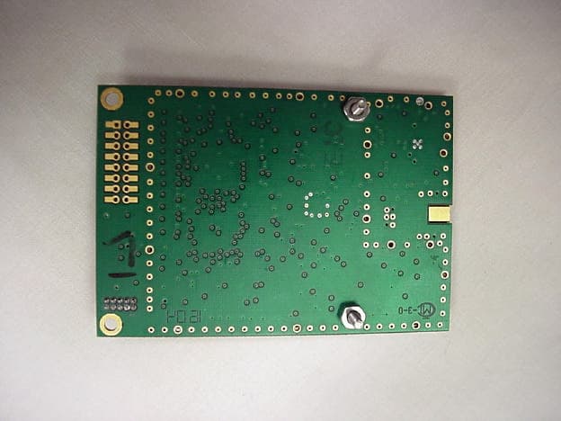
Click to zoom
Application Details
- Equipment Class
- DSS - Part 15 Spread Spectrum Transmitter
- Date of Grant
- Dec 27, 2004
- Application Purpose
- Original Equipment
- Date of Application
- Dec 27, 2004
- Equipment Note
- Frequency Hopping Transceiver
- Frequency Range
- 2401.05600000 - 2474.49600000
- Country
- United States
Documents & Files
Document Text
Text extracted from the exhibit documents filed with the FCC. Open a document above to read the original.
Cover Letter(s)
AGENCY AGREEMENT Federal Communications Commission P.O. Box 429 Columbia, MD 21045 Date: June, 30 2004 Gentlemen: By signature below, we hereby appoint United States Technologies, Inc. (U.S. Tech) to act as our agent with regard to all FCC equipment authorizations. This appointment will remain in effect until otherwise notified. I further certify by signature below that no party (per 47 CFR 1.2002(b)) to the application is subject to a denial of Federal benefits, including FCC benefits, pursuant to Section 5301 of the Anti-Drug Abuse Act of 1988, 21 U.S.C. 853(a). This appointment includes the authority to complete FCC Form 731 on our behalf and sign the application as an authorized agent. Al Patrick,Date: June 30, 2004 Sr. Compliance EngineerAl Patrick Cirronet [email protected] 5375 Oakbrook Parkway Norcross, GA 30093 678 684 2000 ext. 138
Cover Letter(s)
WIT2450 Product EMC Information CONFIDENTIALITY REQUEST Federal Communications Commission Equipment Authorization Branch 7435 Oakland Mills Road Columbia, MD 21046 Date: June, 30 2004 Gentlemen: Cirronet Inc respectfully requests confidentiality of certain materials provided with the submission of the WIT2450 under FCC ID: HSW-2450 in accordance with FCC Regulations 0.459. The confidentiality request applies to the schematics, block diagram, and integration guide. The WIT2450 has been developed at considerable effort and expense by Cirronet Inc.. These items are considered as Trade Secrets and therefore public access to the proprietary material could possible result in duplication of equipment that could severely damage the company's business advantage. I appreciate your assistance in this matter. Sincerely, Al Patrick,Date: June 30, 2004 Sr. Compliance Engineer Cirronet Inc. 5375 Oakbrook Parkway Norcross, GA 30093 678 684 2000 ext. 138 [email protected]
Cover Letter(s)
Friday, October 08, 2004 Dear Application Examiner Regarding Part 15 Unlicensed Modular Transmitter Approval, the following requirements called out in FCC Public Notice DA 00-1407 are observed: 1. The WIT2450M has its own RF shielding. 2. The WIT2450M modular transmitter has buffered modulation/data inputs to ensure that the module will comply with Part 15 requirements under conditions of excessive data rates or over- modulation. 3. The WIT2450M employs on board power supply regulation to the transmitter portion of the module, utilizing IC U12 within the module. 4. The WIT2450M employs a MMCX connector. According to FCC Public Notice, DA 00-2225, the MMCX qualifies as a unique antenna coupler. 5. The WIT2450M was tested in a stand-alone configuration. 6. The WIT2450M has a label with the FCC ID: HSW-2450 7. The WIT2450M complies with FCC 15.247 for Frequency Hopping Spread Spectrum Operation. An Integration Guide is provided for every module sold. This guide instructs the integrator in the proper operation of the device. The text in the guide specifies FCC Part 15 compliance: 8. The use of the WIT2450M in any application where the antenna is 20 cm or less distance to the body for mobile antennas and 2 m or less distance to the body for fixed antennas is not allowed. This is specified in the Integration Guide previous to the Table of Contents. The text follows: FCC s MPE Requirements Information to user/installer regarding FCC s Maximum Permissible Exposure (MPE) limits. Notice to users/installers using the 24 dBi parabolic dish antenna in conjunction with all Cirronet RF products. FCC rules limit the use of this antenna, when connected to Cirronet RF products for point-to-point applications only. It is the responsibility of the installer to ensure that the system is prohibited from being used in point-to- multipoint applications, omni-directional applications, and applications where there are multiple co-located intentional radiators transmitting the same information. Any other mode of operation using this antenna is forbidden. Notice to users/installers using the following fixed antennas, with Cirronet RF products: Andrews 24dBi parabolic dish Andrews 18dBi parabolic dish Hyperlink Technologies 24dBi Parabolic Dish The field strength radiated by any one of these antennas, when connected to Cirronet RF products, may exceed FCC mandated RF exposure limits. FCC rules require professional installation of these antennas in such a way that the general public will not be closer than 2 m from the radiating aperture of any of these antennas. End users of these systems must also be informed that RF exposure limits may be exceeded if personnel come closer than 2 m to the apertures of any of these antennas. Notice to users/installers using the following mobile antennas, with Cirronet RF products: Digital Wireless Corp 3 dBi patch Mobile Mark 6dBi omni-directional, Mobile Mark 9dBi omni-directional, Mobile Mark 9dBi Corner Reflector Mobile Mobile Mark 14dBi Corner Reflector MaxRad 5dBi whip, MaxRad 5dBi Magnetic Mount whip Cirronet 6dBi Patch antenna, Cirronet 12dBi Patch antenna, Ace 2dBi dipole, Cushcraft 15dBi Yagi, Mobile Mark 2.5 dBi Vehicle Mount Stub FCC rules require installation of these antennas in such a way that the general public will not be closer than 20 cm from the radiating aperture of any of these antennas. End users of these systems must also be informed that RF exposure limits may be exceeded if personnel come closer than 20 cm to the apertures of any of these antennas. Al Patrick Sr. Compliance Engineer Cirronet Inc. [email protected]
Cover Letter(s)
October 19, 2004 RE: Cirronet FCC ID: HSW-2450 After a review of the submitted information, I have a few comments on the above referenced Application. Administrative Issues: 1) Please confirm that confidentiality it not requested on the block diagram. If it is, please adjust the confidentiality letter. The confidentiality request has been revised to include the block diagrams 2) It appears that a modular approval is desired for this device. When modular approval is requested, a cover letter addressing each of the modular issues in the FCC guidance document must be provided. Please provide a cover letter addressing each of the modular requirements. A Modular Approval Letter has been provided. 3) In the RF exposure exhibit, please: a) denote and group all mobile antennas together and all fixed antennas together. The exhibit should clearly denote which antennas are for which. The RF Exposure Exhibit has been changed to correct this item. b) Please denote which antennas were tested in this application. That information is listed under the Power Output Section. The information has been bolded to better identify the antennas used for calculation. 4) The RF exposure exhibit lists frequencies from 2400.9 – 2476.2. However the 731 form lists 2401.69 – 2469.89, the test report lists 2400.9 – 2476.85, and the theory of operation cites 2401.6896 – 2469.888. What are the lowest and highest channels? All exhibits should be consistent. Please correct as necessary. These have all been corrected to reflect the range of 2.401056 – 2.474496 GHz. Frequencies listed in test data may vary slightly based upon Spectrum Analyzer Settings. Original Data for conducted Power was taken at 2.47685 GHz, but was later scaled back based upon Band edge results. Final frequency is 2.474496 GHz. 2.47685 is still submitted as a representative output power, as it is consistent with low, low mid, high mid and High Channels. 5) The RF exposure exhibit mentions 2.0 cm for mobile applications. Note that distance should not be calculated for mobile applications as this is assumed to be 20 cm by definition. Please correct. This has been corrected. 6) All point to point antennas should be listed in the users manual to the installer in connection with the first paragraph shown regarding point to point applications. This should likely include the 15 dBi Yagi, 18 dBi parabolic dish antennas, and the 14 dBi corner reflector (which may not apply see below) as well. See new manual attached. 7) Any EIRP that exceeds 36 dBi (maximum conducted power + dBi of antenna) may only be used for point to point applications. Please explain the use of the corner reflector. The EIRP with the corner reflector is 36.5 dBi, which is not allowed if it may be used for applications other than point to point without further power reduction for installation of this antennas (i.e. maximum power of 150 mW for point to multipoint installations). If power is reduced by the installer for these configurations, the device must be professionally installed, the users manual clearly explain what is to be done and how is it done, and any ability to increase/decrease the output power via software must meet with the requirements of 15.15(b) Please explain. The WIT2450 has three power levels. 10dBm – Optional for Europe 18dBm – Default setting for Multipoint operation 23dBm – Point to Point (with low gain antennas or for use in other countries) A cover letter will be provided on the installation instructions manual indicating that power level commands cannot be supplied to the end user. 8) The users manual should clearly list all approved antennas and RF exposure conditions for all antennas (i.e. 20 cm, 52 cm, etc). This information should be simple and easy to understand (i.e. a table grouping by fixed/mobile and listing appropriate distances). See new manual attached. 9) The manual appears to be missing information of 15.21. Please update See new manual attached, page 3. 10) The fixed antenna statement appears to be missing the 18 and 24 dBi Andrews parabolic dish antennas (and possibly others). Please update See new manual attached. 11) The fixed and mobile statements should also include information to inform the installer or user “and must not be co-located or operating in conjunction with any other antenna or transmitter.” Please update See new manual attached. 12) There are several other antennas which are given, which do not appear in the manual, but should likely be listed under the mobile antennas shown. Please update. See new manual attached. 13) Please explain why the users manual cites 2 meters, while the RF exposure is only around 52 cm for fixed antennas. Cirronet wishes to provide a conservative and consistent default of 2 meters in their manuals. 14) Test configuration photographs show some antennas placed directly on the table top. Antennas such as the yagi and corner reflector should not be placed directly on the table top. They should be insulated by foam or cardboard so that they are at least 1 to 2“ above the table top. Please review and correct as necessary. Test results were spot checked using foam and found to provide no deviation in data. 15) The users manual should provide more guidance and instruction to the installers/OEM integrators to instruct the integrator how to properly label the device and specific information to include in the users manual. Example information for other filings may be found on the following page. Please add additional information which covers this information to the users manual. See section 7.8 in new manual provided. 16) The information regarding antenna connections states “reverse-sex TNC or N connector”. Please clarify if this is in reference to a reverse N or standard N connector. Standard connectors are only allowed if professional installation if justified in the application.\ Reverse N 17) FYI...For future power measurements of this type, please ensure that the signal is adequately below the top reference line. N…
Text truncated - open the document above for the full version.
Cover Letter(s)
RE: Cirronet FCC ID: HSW-2450 Enclosed is my response to your comments. After a review of the submitted information, I have a few comments on the above referenced Application. Administrative Issues: 1) Please provide the updated confidentiality Letter referenced in your response. This has been uploaded with the addition of the integration guide. 2) The labeling mentioned in the modular approval letter does not appear to mention the labeling on the device or remainder of the application. What is the correct FCC ID? HSW-2450 3) Item 7 of the modular letter mentions user...This should likely reference integrator instead. Please review. Corrected. 4) Modular approval letter mentions 20 cm only. Corrected 5)Regarding the MPE exhibit, it appears that most antennas are listed for fixed applications. This is unusual. Typically only high gain directional antennas are listed or large omni- directional high gain antennas are listed as fixed. I.E. 2 dBi dipoles can not usually expected to be fixed locations. Additionally, it is to the manufacturer to list as many mobile (in liu of fixed) as possible. Please review. Also note that your worse case justification mentions a 12 dBi patch that does not match your list. Also, the list in the report and the manual for mobile/fixed must be consistent. Call to discuss as necessary. Note the manual does not appear consistent with this list. All items have been corrected in the manual, and regrouped for maximum benefit to Cirronet. 6) Mobile RF exposure calculation should compare result to calculated power density. Please fix. Corrected 6) RF exposure still mentions 2 cm in the first paragraph for mobile application. Please review per our discussion. Typo corrected 8) 7428 MHz in Table 4d does not appear to be denoted properly. Note that while the other data shows a -1 dB high pass filter correction, this plot does not contain this. Was a high pass filter used. If so, then this should be denoted, as well as the 3 to 1 meter correction. Currently the data does not appear to take into consideration the 1 dB correction, but it is uncertain if it should as well. Corrected. 1 db loss from filter was originally calculated but not denoted. 9) My previous references to 2.1033(b)(10) were incorrectly referencing an older version of the rules. What was being requested was information on “the system receivers shall have input bandwidths that match the hopping channel bandwidths of their corresponding transmitters and shall shift frequencies in synchronization with the transmitted signals”. Please provide information for this. This statement on Cirronet letterhead has been uploaded. 10) The users manual states the device meets with Class A emissions. Please explain precautions taken to ensure that Receiver emissions meet with Appropriate limits (these are equivalent to Class B levels). As stated in the report, the unit met Class B levels. The Integration Guide has been corrected to state this. 11) The response to equally on the average references a 17 mS TX time for a remote is 13 mS per channel with a 30 second dwell time. However, information used to calculate average emissions and MPE RF exposure both mention a maximum of 4.86 mS. This information is not consistent. Please review and correct as necessary. Additionally the users manual page 27 suggests a maximum dwell of 17.627 ms. All information appears inconsistent. Note that this may affect previously provided average duty cycle calculations, data and MPE exhibits. Please disregard this response from the customer, as it is incorrect. The values stated are intended for possible EU sales and has been removed from the Integration Guide. As stated in the Average Limits section, the worst case transmit duty cycle yields a maximum transmit time of 4.86 milliseconds. A plot of the transmit channel follows in this letter. 12) Users manual specifications page 41 cite 95 US channels which is not consistent with report. Corrected. 13) Section 7.3 of the users manual appears to suggest the normal N connectors are used and not reverse N connectors. Please review/correct as necessary. Corrected. 14) Section 7.3 of users manual mentions a 12 dBi gain omni which is not consistent with the rest of the application (MPE/Report). Corrected. 15) Note the antenna connection types given in the application (MPE/Report) do not match section 7.3 of users manual. Corrected 16) It appears several approved antennas may not be listed in section 7.3 of the users manual (6 dBi Omni, 12 dBi patch) or in the front cover RF exposure information. Corrected. 17) Please consider adding additional information to the integrator as provided in the end of this document. While portions of this appear to be covered, guidance on RF exposure statements, statement regarding the end user can not be provided instructions on how to install/remove, and following approved mobile/fixed conditions do not appear to be fully addressed. Note current users manual does not appear to address non-colocation requirements as well. 18) Information in the users manual does not appear to explain which power levels are for use with which antennas. This information must be very clear. Additionally, please explain compliance to 15.15 given the various power levels and the integrator adjusts this. Network Commands on page 24 have been modified in the Integration Guide. All units will be provided at 18dBm-output power level (default). Point to Point applications, (3 parabolic dish antennas) will be referenced for higher power level, but the Guide will instruct the integrator to contact Cirronet Customer Support for commands, which they will instruct cannot be released to the end user. 19) Given the various power levels, it appears that the power measured on the high channel may be for the default level and not high power level. Please explain. If necessary, please provide low, middle, and high channel measurements at default levels as well. Identical commands on all frequencies were use…
Text truncated - open the document above for the full version.
Cover Letter(s)
American Telecommunications Certification Body Inc. 6731 Whittier Ave, McLean, VA 22101 October 19, 2004 RE: Cirronet FCC ID: HSW-2450 After a review of the submitted information, I have a few comments on the above referenced Application. Administrative Issues: 1) Please confirm that confidentiality it not requested on the block diagram. If it is, please adjust the confidentiality letter. 2) It appears that a modular approval is desired for this device. When modular approval is requested, a cover letter addressing each of the modular issues in the FCC guidance document must be provided. Please provide a cover letter addressing each of the modular requirements. 3) In the RF exposure exhibit, please: a) denote and group all mobile antennas together and all fixed antennas together. The exhibit should clearly denote which antennas are for which. b) Please denote which antennas were tested in this application. 4) The RF exposure exhibit lists frequencies from 2400.9 – 2476.2. However the 731 form lists 2401.69 – 2469.89, the test report lists 2400.9 – 2476.85, and the theory of operation cites 2401.6896 – 2469.888. What are the lowest and highest channels? All exhibits should be consistent. Please correct as necessary. 5) The RF exposure exhibit mentions 2.0 cm for mobile applications. Note that distance should not be calculated for mobile applications as this is assumed to be 20 cm by definition. Please correct. 6) All point to point antennas should be listed in the users manual to the installer in connection with the first paragraph shown regarding point to point applications. This should likely include the 15 dBi Yagi, 18 dBi parabolic dish antennas, and the 14 dBi corner reflector (which may not apply – see below) as well. 7) Any EIRP that exceeds 36 dBi (maximum conducted power + dBi of antenna) may only be used for point to point applications. Please explain the use of the corner reflector. The EIRP with the corner reflector is 36.5 dBi, which is not allowed if it may be used for applications other than point to point without further power reduction for installation of this antennas (i.e. maximum power of 150 mW for point to multipoint installations). If power is reduced by the installer for these configurations, the device must be professionally installed, the users manual clearly explain what is to be done and how is it done, and any ability to increase/decrease the output power via software must meet with the requirements of 15.15(b) Please explain. 8) The users manual should clearly list all approved antennas and RF exposure conditions for all antennas (i.e. 20 cm, 52 cm, etc). This information should be simple and easy to understand (i.e. a table grouping by fixed/mobile and listing appropriate distances). 9) The manual appears to be missing information of 15.21. Please update 10) The fixed antenna statement appears to be missing the 18 and 24 dBi Andrews parabolic dish antennas (and possibly others). Please update 11) The fixed and mobile statements should also include information to inform the installer or user “and must not be co-located or operating in conjunction with any other antenna or transmitter.” Please update 12) There are several other antennas which are given, which do not appear in the manual, but should likely be listed under the mobile antennas shown. Please update. 13) Please explain why the users manual cites 2 meters, while the RF exposure is only around 52 cm for fixed antennas. --- Continued on Next Page --- z Page 2 October 19, 2004 14) Test configuration photographs show some antennas placed directly on the table top. Antennas such as the yagi and corner reflector should not be placed directly on the table top. They should be insulated by foam or cardboard so that they are at least 1 to 2“ above the table top. Please review and correct as necessary. 15) The users manual should provide more guidance and instruction to the installers/OEM integrators to instruct the integrator how to properly label the device and specific information to include in the users manual. Example information for other filings may be found on the following page. Please add additional information which covers this information to the users manual. 16) The information regarding antenna connections states “reverse-sex TNC or N connector”. Please clarify if this is in reference to a reverse N or standard N connector. Standard connectors are only allowed if professional installation if justified in the application.\ 17) FYI...For future power measurements of this type, please ensure that the signal is adequately below the top reference line. 18) Antenna conducted measurements for spurious should be measured using RBW = 100kHz, VBW > RBW per FCC guidelines. Please correct. 19) Please explain why conducted spurs only appears in antenna conducted plot 4g, and not on the other channels. 20) In table 4a and 4e, did 7203 MHz use the high pass filter or measured at 1 meter? Please review/correct as necessary. 21) 7428 MHz in Table 4d does not appear to be denoted properly. 22) Please comment on the RBW and VBW settings used to take average radiated measurements. 23) The peak plots appear to show that the signal was pulsed during test. Additionally, there appears to be a large difference between peak and average measurements suggesting that inappropriate average settings were used. Note that If the TX was pulsed during testing, then average measurements of RBW=1 MHz, VBW = 10 Hz will likely not be applicable. Please provide a plot of a single frequency with a 0 Hz span to show the duty cycle relationship that the TX had during testing. Please provide cursor measurements to show TXon time, TXoff time, and TXperiod. Note for average measurements to be valid, the VBW must be > 1/Ton time, but preferably > 4* (1/Ton) time. Call to discuss if necessary. Note that the RF exposure information also suggests that maybe a 3 dB average factor may be applied (20 log 0.7). 24) Please confirm the Results of the f…
Text truncated - open the document above for the full version.
Cover Letter(s)
American Telecommunications Certification Body Inc. 6731 Whittier Ave, McLean, VA 22101 December 21, 2004 RE: Cirronet FCC ID: HSW-2450 After a review of the submitted information, I have a few comments on the above referenced Application. Administrative Issues: 1) Please provide the updated confidentiality Letter referenced in your response. 2) The labeling mentioned in the modular approval letter does not appear to mention the labeling on the device or remainder of the application. What is the correct FCC ID? 3) Item 7 of the modular letter mentions user...This should likely reference integrator instead. Please review. 4) Modular approval letter mentions 20 cm only. 5) Regarding the MPE exhibit, it appears that most antennas are listed for fixed applications. This is unusual. Typically only high gain directional antennas are listed or large omni-directional high gain antennas are listed as fixed. I.E. 2 dBi dipoles can not usually expected to be fixed locations. Additionally, it is to the manufacturer to list as many mobile (in liu of fixed) as possible. Please review. Also note that your worse case justification mentions a 12 dBi patch that does not match your list. Also, the list in the report and the manual for mobile/fixed must be consistent. Call to discuss as necessary. Note the manual does not appear consistent with this list. 6) Mobile RF exposure calculation should compare result to calculated power density. Please fix. 7) RF exposure still mentions 2 cm in the first paragraph for mobile application. Please review per our discussion. 8) 7428 MHz in Table 4d does not appear to be denoted properly. Note that while the other data shows a -1 dB high pass filter correction, this plot does not contain this. Was a high pass filter used. If so, then this should be denoted, as well as the 3 to 1 meter correction. Currently the data does not appear to take into consideration the 1 dB correction, but it is uncertain if it should as well. 9) My previous references to 2.1033(b)(10) were incorrectly referencing an older version of the rules. What was being requested was information on “the system receivers shall have input bandwidths that match the hopping channel bandwidths of their corresponding transmitters and shall shift frequencies in synchronization with the transmitted signals”. Please provide information for this. 10) The users manual states the device meets with Class A emissions. Please explain precautions taken to ensure that Receiver emissions meet with Appropriate limits (these are equivalent to Class B levels). 11) The response to equally on the average references a 17 mS TX time for a remote is 13 mS per channel with a 30 second dwell time. However, information used to calculate average emissions and MPE RF exposure both mention a maximum of 4.86 mS. This information is not consistent. Please review and correct as necessary. Additionally the users manual page 27 suggests a maximum dwell of 17.627 ms. All information appears inconsistent. Note that this may affect previously provided average duty cycle calculations, data and MPE exhibits. 12) Users manual specifications page 41 cite 95 US channels which is not consistent with report. 13) Section 7.3 of the users manual appears to suggest the normal N connectors are used and not reverse N connectors. Please review/correct as necessary. 14) Section 7.3 of users manual mentions a 12 dBi gain omni which is not consistent with the rest of the application (MPE/Report). 15) Note the antenna connection types given in the application (MPE/Report) do not match section 7.3 of users manual. ---- Continued on Next Page --- z Page 2 December 21, 2004 16) It appears several approved antennas may not be listed in section 7.3 of the users manual (6 dBi Omni, 12 dBi patch) or in the front cover RF exposure information. 17) Please consider adding additional information to the integrator as provided in the end of this document. While portions of this appear to be covered, guidance on RF exposure statements, statement regarding the end user can not be provided instructions on how to install/remove, and following approved mobile/fixed conditions do not appear to be fully addressed. Note current users manual does not appear to address non-colocation requirements as well. 18) Information in the users manual does not appear to explain which power levels are for use with which antennas. This information must be very clear. Additionally, please explain compliance to 15.15 given the various power levels and the integrator adjusts this. 19) Given the various power levels, it appears that the power measured on the high channel may be for the default level and not high power level. Please explain. If necessary, please provide low, middle, and high channel measurements at default levels as well. 20) The MPE exhibit should adequately reflect the 2 power levels and calculations accurately denote this. Note this typically would require default power level measurements to calculate mobile antennas. 21) Given the nature of information in the users manual, if this manual is only provided to integrators and not the public/end-user, it may be suggested to cover this under confidentiality as well. 22) Information on dwell time appears to mention all 86 channels are used, however information in the users manual section 5.3 suggests that hop-tables can be adjusted with fewer channels. What is the minimum number of hopping channels ever used? Also, please explain compliance to 15.247(g). Additionally how does this affect duty cycle and MPE calculations previously provided. Timothy R. Johnson Examining Engineer mailto: [email protected] The items indicated above must be submitted before processing can continue on the above referenced application. Failure to provide the requested information may result in application termination. Correspondence should be considered part of the permanent submission and may be viewed from the Internet after a Grant of Equipment Auth…
Text truncated - open the document above for the full version.
External Photos
FCC ID: HSW-2450 Photo 1.EUT, 3 Dimensional Front View FCC ID: HSW-2450 Photo 2.EUT, 3 Dimensional Top View FCC ID: HSW-2450 Photo 3.Bottom View of Board
ID Label/Location Info
SECTION 3 LABELING INFORMATION Label will be placed on the bottom of the unit. Cirronet FCC ID: HSW-2450 THIS DEVICE COMPLIES WITH PART 15 OF THE FCC RULES. OPERATION IS SUBJECT TO THE FOLLOWING TWO CONDITIONS. (1) THIS DEVICE MAY NOT CAUSE HARMFUL INTERFERENCE, AND (2) THIS DEVICE MUST ACCEPT ANY INTERFERENCE RECEIVED, INCLUDING INTERFERENCE THAT MAY CAUSE UNDESIRED OPERATION.
Internal Photos
FCC ID: HSW-2450 SEC…
Text truncated - open the document above for the full version.
Contact Information
Applicant
Mark Tucker(Director of Hardware Engineering)
Technical Contact
U.S. TechnologiesLouis A Feudi
[email protected]770-740-0717
3505 Francis Circle · Alpharetta, Georgia · United States
Test Firm
US TechSandy McEnery
Technical Specifications
| # | Rule Parts | Frequency Range | Power Output |
|---|---|---|---|
| 1 | 15C | 2.40 GHz - 2.47 GHz | 179.00 mW |
Other Applications from Murata Electronics North America
HSW2NR
May 13, 2026LBMA0ZZ2NR
Equipment Class
DTS - Digital Transmission SystemHSW2FR
Aug 29, 2024Communication Module
Equipment Class
DTS - Digital Transmission System
HSW2EG
Dec 14, 2022Type 2EG BLE Module
Equipment Class
DTS - Digital Transmission System
HSW-2420
Jul 12, 2021Wireless 2.4 GHz Industrial Transceiver
Equipment Class
DSS - Part 15 Spread Spectrum Transmitter
HSW-608B
Apr 11, 2021Wireless Medical Telemetry Service Radio Module
Equipment Class
TNB - Licensed Non-Broadcast Station Transmitter