HSW-DM1810AWireless Transceiver Module
Murata Electronics North America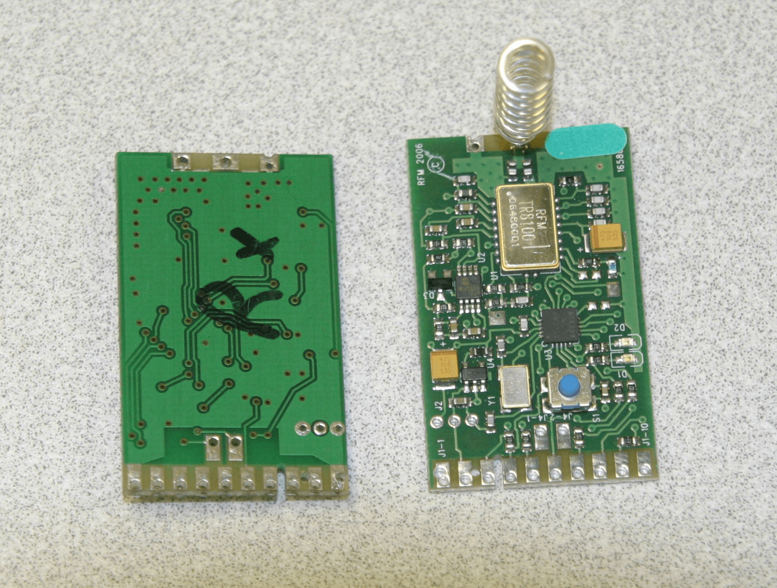
Click to zoom
Application Details
- Equipment Class
- DTS - Digital Transmission System
- Date of Grant
- Jul 09, 2007
- Application Purpose
- Original Equipment
- Date of Application
- Jul 09, 2007
- Equipment Note
- Wireless Transceiver Module
- Frequency Range
- 916.50000000 - 916.50000000
- Country
- United States
Documents & Files
Document Text
Text extracted from the exhibit documents filed with the FCC. Open a document above to read the original.
Users Manual
1 DM1810- 916MB RatingValueUnits All Input/Output Pins Except VIN-0.3 to +3.3V Non-Operating Ambient Temperature Range-40 to 85 o C Absolute Maximum Ratings Electrical Characteristics CharacteristicSymNotesMinimumTypicalMaximumUnits Operating Frequencyf O 916.30916.70MHz Modulation TypeOOK on BPSK Spreading Code RF Encoded Data Transmission Rate4.8kb/s Average Receive Input Current, No External Power Supply LoadI R 5.5mA Receiver Input Signal for 10 -3 BER, 25°C -100dBm Average Transmit Input Current, No External Power Supply LoadI TA 15.75mA Peak Transmit Input Current, No External Power Supply LoadI TP 32mA Peak Transmitter Output PowerP O 10mW Bind Input Logic High2.4V Bind Input Logic Low0.45V Serial Port Data Rate9.6kb/s Average Sleep Input Current, No External Power Supply LoadI SA 60μA Power Supply Input Voltage Range, -40 to +85 o CVIN3.110V Power Supply Input Voltage Range, 0 to +85 o CVIN2.610V Regulated Power Supply Output Voltage, VIN 3.1 to 10 VVOUT3.0Vdc Regulated Power Supply Voltage Ripple10mV P-P Relative Humidity Range, Non-CondensingRH1090% 916.50 MHz Transceiver Module The DM1810-916MB is the 916.50 MHz base station module in the DM1810 family of RF transceiv - ers. The DM1810 family is designed for adding wireless mesh network connectivity to a wide range of monitoring and control systems. The DM1810-916MB is equipped with a serial I/O port to inter - face a host microcontroller. Radio communications range in an “open field” environment is typically 600 meters/hop. The DM1810-916MB combines RFM’s very low current ASH radio technology with low power microcontroller technology to achieve long battery life. This module is compatible with Cirronet’s miniMESH TM network protocol, which provides add-on “plug-and-play” multicast mesh network routing. The DM1810-916MB is certified for operation under FCC 15.247 and Canadian RSS 210 regulations. • Base Station with Host Serial Interface • Compatible with Cirronet miniMESH TM Network Protocol • 3 V, Very Low Current Operation • Ready-to-Use OEM Module 2 Theory of Operation The major components of the DM1810-916MB include an RFM TR8100 ASH transceiver and a Microchip PIC16F689 microcontroller. The TR8100 operates on a frequency of 916.50 MHz, at a nominal output power of 10 mW. The 16F689 provides a 9.6 kb/s serial interface for communication with a host microcontroller. A compan - ion interface board, the IM1800, is available with USB bridge circuitry to interface the DM1810-916MB to a host PC. The DM1810 includes two LEDs that indicate the module’s operating mode. The DM1810-916MB firmware is based on Cirronet’s miniMESH network protocol, which utilizes time-syn - chronized redundant routing to provide robust, deter - ministic packet delivery though a network with up to 15 routers. Network configuration and maintenance fea - tures are built into the miniMESH protocol, simplifying commissioning and operating logistics. The firmware also includes several sleep cycling methods for ex - tended battery life operation. Please refer to theDM1810 User’s Guideand the AN1810 series Application Notesfor installation and application programming information. See Cirronet’s web site at www.Cirronet.com. DM1810-916MB FCC Certification The DM1810-916MB hardware has been certified for operation under FCC Part 15 Rules, Section 15.247. The antenna(s) used for this transmitter must be in- stalled to provide a separation distance of at least 20 cm from all persons and must not be co-located or operating in conjunction with any other antenna or transmitter. FCC Notices and Labels This device complies with Part 15 of the FCC rules. Operation is subject to the following two conditions: (1) this device may not cause harmful interference, and (2) this device must accept any interference re - ceived, including interference that may cause unde - sired operation. A clearly visible label is required on the outside of the user’s (OEM) enclosure stating that this product con - tains a DM1810-916MB transceiver assembly, FCC ID: HSW-DM1810A. WARNING: This device oper - ates under Part 15 of the FCC rules. Any modification to this device, not expressly authorized by Cirronet, Inc., may void the user’s authority to operate this de - vice. TXMOD RX DATA CNTRL1 CNTRL0 PIC 16F689 μP DM1810-916MB Block Diagram LED 1 LED 2 TR8100 ASH Transceiver GND SERIAL TX SERIAL RX BIND GND VOUT VIN 3 V Reg GND GND J1-1 J1-2 J1-3 J1-4 J1-5 J1-6 J1-7 J1-8 J1-9 J1-10 J3-2 J3-1 J3-3 RSSI J4-1 J4-2 D1 D2 Figure 1 Canadian Department of Communications Industry Notice - IC: 4492A-DM1810A This apparatus complies with Health Canada’s Safety Code6/ICRSS210. To prevent radio interference to the licensed service, this device is intended to be operated indoors and away from windows to provide maximum shielding. Equipment (or its transmit antenna) that is installed outdoors may be subject to licensing. ICES-003 This digital apparatus does not exceed the Class B limits for radio noise emissions from digital apparatus as set out in the radio interference regulations of In - dustry Canada. Le present appareil numerique n’emet pas de bruits radioelectriques depassant les limites applicables aux appareils numeriques de Classe B prescrites dans le reglement sur le brouillage radioelectrique edicte par Industrie Canada. 3 PinNameDescription J1-1GNDThis pad is a signal and power supply ground. J1-2VINThis is the power supply input pad. The allowed input voltage range is 2.6 to 10 V. J1-3VOUT VOUT tracks 50 to 100 mV below VIN when VIN is in the range of 2.6 to 3.1 V. When VIN is in the range of 3.1 to 10 V, VOUT is regulated at 3.0 Vdc. Up to 10 mA can be supplied from this pad for powering external circuits such as thermistor-resistor networks. External circuitry must not impress more than 10 mV p-p ripple on the regu - lated output voltage. J1-4BIND This pad is connected to a logic input on the microcontroller, and is configured with a weak pull-up. When this pin is momentarily grounded to J1-1 o…
Text truncated - open the document above for the full version.
Block Diagram
T X M O D R X D A T A C N T R L 1 C N T R L 0 P I C 1 6 F 6 8 9 μ P D M 1 8 1 0 - 9 1 6 B l o c k D i a g r a m L E D 1 L E D 2 T R 8 1 0 0 A S H T r a n s c e i v e r G N D S E R I A L T X S E R I A L R X D I G I T A L O U T A N A L O G I N D I G I T A L I N B I N D G N D V O U T V I N 3 V R e g G N D G N D J 1 - 1 J 1 - 2 J 1 - 3 J 1 - 4 J 1 - 5 J 1 - 6 J 1 - 7 J 1 - 8 J 1 - 9 J 1 - 1 0 J 3 - 2 J 3 - 1 J 3 - 3 R S S I J 4 - 1 J 4 - 2 D 1 D 2 E x t e r n a l C r y s t a l R e f e r e n c e - 8 M H z T r a n s m i t t e r : I n t e r n a l 9 1 6 . 5 M H z R F O s c i l l a t o r a n d 4 6 0 . 8 k c / s S p r e a d i n g C o d e O s c i l l a t o r R e c e i v e r : I n t e r n a l 4 6 0 . 8 k H z A m p l i f i e r S e q u e n c i n g P u l s e G e n e r a t o r
Cover Letter(s)
9 th July 2007 To whom it may concern; In accordance with Public Notice DA 00-1407 dated June 2000, Cirronet, an RF Monolithics Company, wish to apply for modular approval of the DM1810 module, FCC ID: HSW-DM1810A. Each requirement is addressed individually below; 1)The modular transmitter must have its own RF shielding. This is intended to ensure that the module does not have to rely upon the shielding provided by the device into which it is installed in order for all modular transmitter emissions to comply with Part 15 limits. It is also intended to prevent coupling between the RF circuitry of the module and any wires or circuits in the device into which the module is installed. Such coupling may result in non- compliant operation. The DM1810 Modules are all based on RFM’s Amplifier Switched Hybrid (ASH) Technology, which is fully shielded in its own metal package and has been type certified by the FCC. •2) The modular transmitter must have buffered data inputs (if such inputs are provided). This is intended to ensure that the module will comply with Part 15 requirements in the event of excessive data rates or over- modulation conditions. The ASH Transceiver is buffered by the 16F689 PIC Microprocessor. All inputs to the Transceiver come through the micro and the data rate to and from the radio is fixed at 4.8kb/s •3) The modular transmitter must have its own power supply regulation. This is intended to ensure that the module will comply with Part 15 requirements regardless of the design of the power supplying circuitry in the device into which the module is installed. The on board regulator powers both the micro and ASH device •4) The modular transmitter must comply with the requirements of Section 15.203 - the antenna must either be permanently attached or employ a “unique” antenna coupler (at all connections between the module and the antenna, including the cable). The “professional installation” provision of this Section may not be applied to modules. Please note that Section 15.204(c) also applies to modules - any antenna used with the module must be approved with the module, either at the time of initial authorization or through a Class II permissive change. Antennas for the DM1810-916 Modules are soldered in place. 5) The modular transmitter must be tested in a stand-alone configuration, i.e., the antenna, AC or DC power, and data input/output lines must be connected to the module, but the module must not be inside another The DM1810 Modules have met this requirement and have been fully tested. device during testing. This is intended to demonstrate that the module is capable of complying with Part 15 emission limits regardless of the device into which it is eventually installed. Unless the transmitter module will be battery powered, it must comply with the AC line conducted requirements found in Section 15.207. AC or DC power lines and data input/output lines connected to the module must not contain ferrites, unless they will be marketed with the module (see Section 15.27(a)). The length of these lines shall be the length typical of actual usage or, if that length is unknown, at least 10 centimeters to insure that there is no coupling between the case of the module and supporting equipment. Any accessories, peripherals, or support equipment connected to the module during testing shall be unmodified or commercially available (see Section 15.31(i)). •6) The modular transmitter must be labeled with its own FCC ID number, and, if the FCC ID is not visible when the module is installed inside another device, then the outside of the device into which the module is installed must also display a label referring to the enclosed module. This exterior label can use wording such as the following: “Contains Transmitter Module FCC ID: HSW- DM1810A” or “Contains FCC ID: HSW- DM1810A” Any similar wording that expresses the same meaning may be used. The Grantee may either provide such a label, an example of which must be included in the application for equipment authorization, or, must provide adequate instructions along with the module which explain this requirement. In the latter case, a copy of these instructions must be included in the application for equipment authorization. We have visible labels on the top of the device to meet this requirement. If a DM1810 Module is installed in another package, the outside package must display a external label with wording such as the following: “Contains Transmitter Module FCC ID: HSW- DM1810A” or “Contains FCC ID: HSW- DM1810A” •7) The modular transmitter must comply with any specific rule or operating requirements applicable to the transmitter and the manufacturer must provide adequate All DM1810 modules meet this requirement as is. Customers can not operate the device in a way that will not comply to these specifications. instructions along with the module to explain any such requirements. A copy of these instructions must be included in the application for equipment authorization. For example, only cordless phones are permitted to operate under Section 15.233, thus, a module authorized under this Section would be limited to use in cordless phones and the instructions provided with the device must explain this limitation. •8) In the case of a modular transceiver, the modular approval policy only applies to the transmitter portion of such devices. Pursuant to Section 15.101(b), the receiver portion will either be subject to Verification, or it will not be subject to any authorization requirements (unless it is a Scanning Receiver, in which case it is also subject to Certification, pursuant to Section 15.101(a)). Receiver in the DM1810 Module meets all requirements and is shown in Nemko report. •9) FCC Rules in Sections 2.1091, 2.1093 and specific Sections of Part 15, including 15.319(i), 15.407(f), 15.253(f) and 15.255(g), require that Unlicensed PCS, UNII and millimeter wave devices perform routine environmental evaluation for RF Exposure to demonstr…
Text truncated - open the document above for the full version.
Operational Description
The monopole antennas used for the DM1810-916 modules are 3.1“long, 22 gauge single strand coated wire, tuned to ¼ wavelength at 916.5 MHz. The antennas can be extended perpendicular to the PC board or bent 90 degrees to extend from the top of the PC board parallel to the module. Both antenna configurations have been tested and found to comply to FCC Part 15.247 for use with these modules.
Operational Description
The DM1810-916MB is the 916.50 MHz base station module in the DM1810 family of RF transceivers. The DM1810 family is designed for adding wireless mesh network connectivity to a wide range of monitoring and control systems. The DM1810-916MB is equipped with a serial I/O port to interface a host microcontroller. Radio communications range in an “open field” environment is typically 600 meters/hop. The DM1810-916MB combines RFM’s very low current ASH radio technology with low power microcontroller technology to achieve long battery life. This module is compatible with RFM’s miniMESH TM network protocol, which provides add-on “plug-and-play” multicast mesh network routing. The DM1810-916MB is certified for operation under FCC 15.247 regulations.
Test Report
Nemko Test Report: 2171RUS1 Applicant: RF Monolithics, Inc. 4441 Sigma Road Dallas, Texas 75244 USA Equipment Under Test: DM1810 Mesh Modules (E.U.T.) In Accordance With: FCC Part 15, Subpart C, 15.247 Digital Transmission System Transmitter Tested By: Nemko USA, Inc. 802 N. Kealy Lewisville, Texas 75057-3136 TESTED BY: DATE : 12 April 2007 David Light, Senior Wireless Engineer APPROVED BY: DATE : 13 th April 2007 Harry Ward, Verifier Number of Pages: 34 Nemko USA, Inc. FCC PART 15, SUBPART C Digital Transmission Systems EQUIPMENT: DM1800 Mesh Modules Test Report No.: 2171RUS1 Page 2 of 30 Table of Contents SECTION 1. SUMMARY OF TEST RESULTS 3 SECTION 2. EQUIPMENT UNDER TEST (E.U.T.) 5 SECTION 3. OCCUPIED BANDWIDTH 7 SECTION 4. MAXIMUM PEAK OUTPUT POWER 9 SECTION 5. RADIATED SPURIOUS EMISSIONS 11 SECTION 6. PEAK POWER SPECTRAL DENSITY 18 SECTION 7. RECEIVER SPURIOUS EMISSIONS 20 SECTION 8. TEST EQUIPMENT LIST 21 ANNEX A - TEST DETAILS 22 ANNEX B - TEST DIAGRAMS 29 Nemko USA, Inc. FCC PART 15, SUBPART C Digital Transmission Systems EQUIPMENT: DM1800 Mesh Modules Test Report No.: 2171RUS1 Section 1. Summary of Test Results Manufacturer: RF Monolithics, Inc. Model No.: DM1810-916MN (Node Module) DM1810-916MR (Router Module) DM1810-916MB (Base station Module) Serial No.: None General: All measurements are traceable to national standards. These tests were conducted on a sample of the equipment for the purpose of demonstrating compliance with Part 15, Subpart C, Paragraph 15.247 for Digital Transmission Systems. Radiated tests were conducted is accordance with ANSI C63.4-2003. Radiated emissions are made on an open area test site. A description of the test facility is on file with the FCC. New Submission Production Unit Class II Permissive Change Pre-Production Unit THIS TEST REPORT RELATES ONLY TO THE ITEM(S) TESTED. THE FOLLOWING DEVIATIONS FROM, ADDITIONS TO, OR EXCLUSIONS FROM THE TEST SPECIFICATIONS HAVE BEEN MADE. See “ Summary of Test Data”. Nemko USA Inc. authorizes the above named company to reproduce this report provided it is reproduced in its entirety and for use by the company’s employees only. Any use which a third party makes of this report, or any reliance on or decisions to be made based on it, are the responsibility of such third parties. Nemko USA Inc. accepts no responsibility for damages, if any, suffered by any third party as a result of decisions made or actions based on this report. This report applies only to the items tested. Page 3 of 30 Nemko USA, Inc. FCC PART 15, SUBPART C Digital Transmission Systems EQUIPMENT: DM1800 Mesh Modules Test Report No.: 2171RUS1 Page 4 of 30 Summary Of Test Data NAME OF TEST PARA. NO. RESULT Powerline Conducted Emissions 15.207(a) NA Minimum 6 dB Bandwidth 15.247(a)(2) Complies Maximum Peak Power Output 15.247(b)(3) Complies Conducted Spurious Emissions 15.247(d) NT Radiated Spurious Emissions 15.247(d)/15.209(a) Complies Peak Power Spectral Density 15.247(e) Complies Footnotes: NA – The device is battery powered. NT – The device has integral antenna(s). Nemko USA, Inc. FCC PART 15, SUBPART C Digital Transmission Systems EQUIPMENT: DM1800 Mesh Modules Test Report No.: 2171RUS1 Page 5 of 30 Section 2. Equipment Under Test (E.U.T.) General Equipment Information Frequency Band (MHz): 902-928 2400-2483.5 5725-5850 Operating Frequency of Test Sample: 916.5 +/-200 kHz Channel Spacing: Single channel operation User Frequency Adjustment: None Input Power: Nemko USA, Inc. FCC PART 15, SUBPART C Digital Transmission Systems EQUIPMENT: DM1800 Mesh Modules Test Report No.: 2171RUS1 Description of EUT The DM1800 family is designed for adding wireless mesh network connectivity to a wide range of monitoring and control systems. The device operates on a single channel in the 900 MHz ISM band. System Diagram Page 6 of 30 Nemko USA, Inc. FCC PART 15, SUBPART C Digital Transmission Systems EQUIPMENT: DM1800 Mesh Modules Test Report No.: 2171RUS1 Page 7 of 30 Section 3. Occupied Bandwidth NAME OF TEST: Occupied Bandwidth PARA. NO.: 15.247(a)(2) TESTED BY: David Light DATE: 12 April 2007 Test Results: Complies. Measurement Data: See 6 dB BW plot Measured 6 dB bandwidth: 1.07 MHZ Channel Separation: NA Test Conditions: 40 %RH 22 °C Measurement Uncertainty: +/-1x10 -7 ppm Test Equipment Used: 1464-1484-1485-993 Nemko USA, Inc. FCC PART 15, SUBPART C Digital Transmission Systems EQUIPMENT: DM1800 Mesh Modules Test Report No.: 2171RUS1 Test Data – Occupied Bandwidth Page 8 of 30 Nemko USA, Inc. FCC PART 15, SUBPART C Digital Transmission Systems EQUIPMENT: DM1800 Mesh Modules Test Report No.: 2171RUS1 Page 9 of 30 Section 4. Maximum Peak Output Power NAME OF TEST: Maximum Peak Output power PARA. NO.: 15.247(b)(3) TESTED BY: David Light DATE: 12 April 2007 Test Results: Complies. Measurement Data: Refer to attached data Maximum PEAK conducted power is estimated to be 5.8 mW (7.6dBm) max based on stated antenna gain of 0 dBi. Test Conditions: 40 %RH 22 °C Measurement Uncertainty: +/-1.7 dB Test Equipment Used: 1464-1484-1485-993 This device was tested at +/- 15% input power per 15.31(e), with no variation in output power. For battery powered equipment, the device was tested with a fresh battery per 15.31(e). The device was tested on three channels per 15.31(m). This test was performed radiated. Nemko USA, Inc. FCC PART 15, SUBPART C Digital Transmission Systems EQUIPMENT: DM1800 Mesh Modules Test Report No.: 2171RUS1 Test Data – Peak Power EIRP Substitution Method Page 1 of 1 Complete X Job No.:2171Date: 4/12/2007Preliminary Specification:15.247(b)(3)Temperature(°C): 40 Tested By:David LightRelative Humidity(%) 22 E.U.T.:DM1800 Configuration:Tx modulated signal Sample No:1/2/3/4 Location:AC 3RBW:2 MHzMeasurement Detector Type:PeakVBW:3 MHz Distance: 3m Test Equipment Used Antenna:993Directional Coupler: Pre-Amp: Cable #1:1484 Filter: Cable #2:1485 Receiver:1464Cable #3: Attenuator #1 Cable #4: Attenuator #2: Mixer: Additional equipment used: Measurement Uncertai…
Text truncated - open the document above for the full version.
Contact Information
Applicant
Mark Tucker(Director of Hardware Engineering)
Test Firm
Nemko Dallas, Inc.Michael Cantwell
Technical Specifications
| # | Rule Parts | Frequency Range | Power Output |
|---|---|---|---|
| 1 | 15C | 916.5 MHz - 916.5 MHz | 5.75 mW |
Other Applications from Murata Electronics North America
HSW2NR
May 13, 2026LBMA0ZZ2NR
Equipment Class
DTS - Digital Transmission SystemHSW2FR
Aug 29, 2024Communication Module
Equipment Class
DTS - Digital Transmission System
HSW2EG
Dec 14, 2022Type 2EG BLE Module
Equipment Class
DTS - Digital Transmission System
HSW-2420
Jul 12, 2021Wireless 2.4 GHz Industrial Transceiver
Equipment Class
DSS - Part 15 Spread Spectrum Transmitter
HSW-608B
Apr 11, 2021Wireless Medical Telemetry Service Radio Module
Equipment Class
TNB - Licensed Non-Broadcast Station Transmitter