HSW-DNT24Spread Spectrum Wireless Transceiver
Murata Electronics North America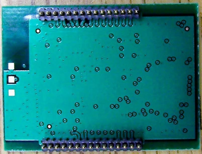
Click to zoom
Application Details
- Equipment Class
- DTS - Digital Transmission System
- Date of Grant
- Oct 20, 2011
- Application Purpose
- Original Equipment
- Date of Application
- Oct 19, 2011
- Equipment Note
- Spread Spectrum Wireless Transceiver
- Frequency Range
- 2406.00000000 - 2475.00000000
- Country
- United States
Documents & Files
Document Text
Text extracted from the exhibit documents filed with the FCC. Open a document above to read the original.
Users Manual
www.RFM.com Technical support +1.678.684.2000 Page 1 of 83 © 2011 by RF Monolithics, Inc. E-mail: [email protected] DNT24 Integration Guide - 10/19/11 DNT24 Series 2.4 GHz Spread Spectrum Wireless Transceivers Integration Guide www.RFM.com Technical support +1.678.684.2000 Page 2 of 83 © 2011 by RF Monolithics, Inc. E-mail: [email protected] DNT24 Integration Guide - 10/19/11 Important Regulatory Information RFM Product FCC ID: HSW-DNT24 I C 4492A-DNT24 Note: This equipment has been tested and found to comply with the limits for a Class B digital device, pursuant to Part 15 of the FCC Rules. These limits are designed to provide reasonable pro- tection against harmful interference in a residential installation. This equipment generates, uses and can radiate radio frequency energy and, if not installed and used in accordance with the in- structions, may cause harmful interference to radio communications. If this equipment does cause harmful interference to radio or television reception, which can be determined by turning the equipment off and on, the user is encouraged to try to correct the interference by one or more of the following measures: 1) Re-orientate or relocate the receiving antenna, 2) Increase the separation between the equipment and the radiator, 3) Connect the equipment into an outlet on a circuit different from that to which the receiver is connected, 4) Consult the dealer or an experienced radio/TV technician for help. FCC Antenna Gain Restriction: The DNT24 has been designed to operate with any dipole antenna of up to 12 dBi of gain, any corner reflector antenna of up to 14 dBi gain, any patch antenna of up to 12 dBi gain, or any chip antenna of up to 1.7 dBi gain. The antenna(s) used for this transmitter must be installed to provide a separation distance of at least 20 cm from all persons and must not be co-located or operating in conjunction with any other antenna or transmitter. IC RSS-210 Detachable Antenna Gain Restriction: This radio transmitter, IC 4492A-DNT24, has been approved by the Industry Canada to operate with the antenna types listed below with the maximum permissible gain and the required antenna impedance for each antenna type indicated. Antenna types not included in this list, having a gain greater than the maxi- mum gain indicated for that type, are strictly prohibited for use with this device. Le présent émetteur radio IC 4492A-DNT24 a été approuvé par Industrie Canada pour fonctionner avec les types d'antenne énumérés ci-dessous et ayant un gain admissible maximal et l'impédance requise pour chaque type d'antenne. Les types d'antenne non inclus dans cette liste, ou dont le gain est supérieur au gain maximal indiqué, sont strictement interdits pour l'exploitation de l'émetteur. Type Model Number Gain Impedance Omnidirectional OD12-2400 12 dBi 50 ohm Corner SCR14-2400CT 14 dBi 50 ohm Patch PA2412 12 dBi 50 ohm Chip FR05-S1-N-0-102 1.7 dBi 50 ohm www.RFM.com Technical support +1.678.684.2000 Page 3 of 83 © 2011 by RF Monolithics, Inc. E-mail: [email protected] DNT24 Integration Guide - 10/19/11 Under Industry Canada regulations, this radio transmitter may only operate using an antenna of a type and maximum (or lesser) gain approved for the transmitter by Industry Canada. To reduce potential radio interference to other users, the antenna type and its gain should be so chosen that the equivalent isot- ropically radiated power (e.i.r.p.) is not more than that permitted for successful communication. Conformément à la réglementation d'Industrie Canada, le présent émetteur radio peut fonctionner avec une antenne d'un type et d'un gain maximal (ou inférieur) approuvé pour l'émetteur par Industrie Canada. Dans le but de réduire les risques de brouillage radioélectrique à l'intention des autres utilisateurs, il faut choisir le type d'antenne et son gain de sorte que la puissance isotrope rayonnée équivalente (p.i.r.e.) ne dépasse pas l'intensité nécessaire à l'établissement d'une communication sat- isfaisante. This device complies with Industry Canada licence-exempt RSS standard(s). Operation is subject to the following two conditions: (1) this device may not cause interference, and (2) this device must accept any interference, including interference that may cause undesired operation of the device. Le présent appareil est conforme aux CNR d'Industrie Canada applicables aux appareils radio exempts de licence. L'exploitation est autorisée aux deux conditions suivantes : (1) l'appareil ne doit pas produire de brouillage, et (2) l'utilisateur de l'appareil doit accepter tout brouillage radioélectrique subi, même si le brouillage est susceptible d'en compromettre le fonctionnement. See Section 6.8 of this manual for regulatory notices and labeling requirements. Changes or modifica- tions to a DNT24 not expressly approved by RFM may void the user’s authority to operate the module. www.RFM.com Technical support +1.678.684.2000 Page 4 of 83 © 2011 by RF Monolithics, Inc. E-mail: [email protected] DNT24 Integration Guide - 10/19/11 Table of Contents 1.0 DNT24 Introduction.......................................................................................................................... 6 1.1 Why Spread Spectrum? ............................................................................................................ 6 1.2 Frequency Hopping versus Direct Sequence ........................................................................... 7 2.0 DNT24 System Overview ................................................................................................................ 8 2.1 Point-to-Point Systems.............................................................................................................. 8 2.2 Point-to-Multipoint Systems ...................................................................................................... 9 2.3 Store-and-Forward Systems ..........................................................................................…
Text truncated - open the document above for the full version.
Users Manual
www.RFM.com Technical support +1.678.684.2000 Page 43 of 83 © 2011 by RF Monolithics, Inc. E-mail: [email protected] DNT24 Integration Guide - 10/19/11 HeartbeatInterval - when set to 0, all heartbeats are disabled, including the initial heartbeat issued after link acquisition. When set to 0xFFFF (default), periodic heartbeats are disabled but the initial linkup heart- beat is enabled. The periodic heartbeat interval is scaled 1 second/count, and applies to DNT24s where sleep mode is disabled. Remotes with sleep mode enabled must have periodic reports and/or ADC sam- pling enabled for heartbeats to be generated. SystemId - this parameter holds the ID for a DTN24 system. DNT24 systems that may physically overlap must have different system IDs. EndToEndAckEnable - when this parameter is set to 1 and the module is in protocol mode, the originator will indicate in its transmitted packet that an ACK is expected from the packet’sdestination node. Setting this parameter to 0x00 reduces network congestion in a store-and-forward system, but no TxDataReply will be sent from the destination to confirm reception. LinkRetryInterval - when a remote enters sleep mode with any packet unsent in its transmit queue, if this parameter is set to a non-zero value, the remote will wake up after the specified number of seconds and try to link so that pending packets can be transmitted. When set to 0, this feature is disabled. FastBeaconCount - this parameter controls the fast beacon mode, which is used to speed up network synchronization. Fast beacon mode is especially useful for multi-level store-and-forward networks that are configured with long hop durations. Fast beacon mode is controlled by the base station. If the Fast- BeaconCount parameter is set to a non-zero value, when the base is reset, powered up or the Fast- BeaconTrig parameter is set to a non-zero value, it will output the number of 6 ms beacons specified in theFastBeaconCount parameter. The base and all of its children will synchronously decrement a version of the parameter in their beacons, such that it will reach 0 simultaneously on all devices. This allows all nodes in the DNT24 system to simultaneously transition to using the configured base slot size and num- ber of slots. The beacons also inform all child devices that the network is in Fast beacon mode, so that all children will observe the FastBeaconCount and assume, in addition to the 6ms hop timing, a base slot size of 0 and a number of slots equal to 1. If the cycled base station operating parameters transmitted in the beacons, including the BaseSlotSize and NumSlots (see Bank 0x01 parameters) are stable, then a further speedup of synchronization can be achieved by setting the NumBaseParms on the base station to 8. However, this should be done only after all child devices are known to have configuration parameters identical to the base station’s saved in their EEPROM. The first 8 parameters contain the AES counter and MAC address that are needed to synchronize encryption, along with NumBaseParms. FastBeaconTrig - when this parameter is set to any non-zero value on a base station, fast beacon mode starts if the fastBeaconCount register is already set to a non-zero value. It auto-clears on a base station and will read back as 0 after it is cleared. On a router or remote, it would do nothing and will not clear except after reset. www.RFM.com Technical support +1.678.684.2000 Page 44 of 83 © 2011 by RF Monolithics, Inc. E-mail: [email protected] DNT24 Integration Guide - 10/19/11 7.4.2 Bank 0x01 - System Settings Bank 1 holds configuration parameters to be input to the base only. The base passes these parameters to the routers and remotes as needed. The exception is InitFrequencyBand parameter which can also be set in routers and remotes. BankLocationNameR/WSizeRangeDefault 0x01 0x00 InitFrequencyBand R/W 0x01 0..11, 255 0 (US) 0x01 0x01 NumSlots R/W 0x01 1..8 3 0x01 0x02 BaseSlotSize R/W 0x01 6..105 40 0x01 0x03 SlotLease R/W 0x01 1..255 2 (hops) 0x01 0x04 BcstAttemptLimit R/W 0x01 0..254 1 0x01 0x05 ArqAttemptLimit R/W 0x01 1..255 6 0x01 0x06 LinkDropThreshold R/W 0x01 1..255 10 (hops) 0x01 0x07 P2PReplyTimeout R/W 0x01 0..255 100 (hops) 0x01 0x08 RegistryTimeout R/W 0x01 0..255 50 (hops) 0x01 0x09 NumBaseParms R/W 0x01 8..21 21 Table 7.4.2.1 InitFrequencyBand - this parameter sets the range of frequencies and channel spacing over which the DNT24 system will initially operate. Twelve bands are available: Subband Channels Frequency Range(s) Notes 0x00 24 2406 - 2475 MHz General purpose 24 channel band 0x01 15 2433 - 2475 MHz 15 channel band, avoids 802.11b/g channels 1-2 0x02 15 2406 - 2475 MHz 15 channel band, avoids 802.11b/g channels 3 0x03 15 2406 - 2475 MHz 15 channel band, avoids 802.11b/g channels 4 0x04 15 2406 - 2475 MHz 15 channel band, avoids 802.11b/g channels 5 0x05 15 2406 - 2475 MHz 15 channel band, avoids 802.11b/g channels 6 0x06 15 2406 - 2475 MHz 15 channel band, avoids 802.11b/g channels 7 0x07 15 2406 - 2475 MHz 15 channel band, avoids 802.11b/g channels 8 0x08 15 2406 - 2475 MHz 15 channel band, avoids 802.11b/g channels 9 0x09 15 2406 - 2475 MHz 15 channel band, avoids 802.11b/g channels 10 0x0A 15 2406 - 2475 MHz 15 channel band, avoids 802.11b/g channels 11 0x0B 15 2406 - 2448 MHz 15 channel band for operation in France 0x0C 5 2406 - 2466 MHz 5 channel band for fast linking, use US and Canada only 0x0D 5 2415 - 2475 MHz 5 channel band for fast linking, use in US and Canada only 0xFF Auto Auto Autoscan for remote to match base Table 7.4.2.2 www.RFM.com Technical support +1.678.684.2000 Page 45 of 83 © 2011 by RF Monolithics, Inc. E-mail: [email protected] DNT24 Integration Guide - 10/19/11 NumSlots - this parameter sets the number of slots available for child transmissions following the parent’s beacon transmission on a hop. BaseSlotSize - this parameter set the maximum number of payload bytes that the base can send on a single hop. The default value is 40 bytes. Slo…
Text truncated - open the document above for the full version.
Cover Letter(s)
Page 1 of 3 September 29, 2011 ATCB Applications Examiner RE: Limited Modular Approval for CIRRONET CORP., FCC ID: HSW-DNT24 Dear Application Examiner: Regarding Part 15 Unlicensed Modular Transmitter Approval, the following requirements called out in FCC Public Notice DA 00-1407 are observed: 1) The modular transmitter must have its own RF shielding. This is intended to ensure that the module does not have to rely upon the shielding provided by the device into which it is installed in order for all modular transmitter emissions to comply with Part 15 limits. It is also intended to prevent coupling between the RF circuitry of the module and any wires or circuits in the device into which the module is installed. Such coupling may result in non-compliant operation. The CIRRONET CORP. model DNT24 is a completely self contained radio which has its own RF shielding on the RF section. No other RF shielding is required or implemented. 2) The modular transmitter must have buffered modulation/data inputs (if such inputs are provided) to ensure that the module will comply with Part 15 requirements under conditions of excessive data rates or overmodulation. The CIRRONET CORP. model DNT24 is a completely self contained radio which modulates its own RF transmitter. It controls the data flow to the transmitter section compliant with Part 15 requirements. 3) The modular transmitter must have its own power supply regulation. This is intended to ensure that the module will comply with Part 15 requirements regardless of the design of the power supplying circuitry in the device into which the module is installed. The module itself has no self-contained power regulator, thus the “Limited” scope of this request. However, the CIRRONET CORP. model DNT24 is a radio module intended for use in products which will ONLY employ 5VDC to the module. Therefore, in all its designs, CIRRONET CORP. will always ensure that the CIRRONET CORP. model DNT24 radio receives 5.0VDC to the power input port of the module in order to comply with the scope of this certification. 4) The modular transmitter must comply with the antenna requirements of Section 15.203 and 15.204(c). The antenna must either be permanently attached or employ a “unique” antenna coupler (at all connections between the module and the antenna, including the cable). Any antenna used with the module must be approved with the module, either at the time of initial authorization or through a Class II permissive change. The “professional installation” provision of Section 15.203 may not be applied to modules. For this application the CIRRONET CORP. model DNT24 employs a permanently attached antenna only. Page 2 of 3 5) The modular transmitter must be tested in a stand-alone configuration, i.e., the module must not be inside another device during testing. This is intended to demonstrate that the module is capable of complying with Part 15 emission limits regardless of the device into which it is eventually installed. Unless the transmitter module will be battery powered, it must comply with the AC line conducted requirements found in Section 15.207. AC or DC power lines and data input/output lines connected to the module must not contain ferrites, unless they will be marketed with the module (see Section 15.27(a)). The length of these lines shall be length typical of actual use or, if that length is unknown, at least 10 centimeters to insure that there is no coupling between the case of the module and supporting equipment. Any accessories, peripherals, or support equipment connected to the module during testing shall be unmodified or commercially available (see Section 15.31(i)). The module itself was tested while connected to an evaluation board, thus the “Limited” scope of this request. However, the CIRRONET CORP. model DNT24 is a radio module intended for use in products which will ONLY employ the same circuitry as that of the evaluation board. Therefore, in all its designs, CIRRONET CORP. will always ensure that the CIRRONET CORP. model DNT24 radio is connected to CIRRONET CORP approved circuitry in order to comply with the scope of this certification. 6) The modular transmitter must be labeled with its own FCC ID number, and, if the FCC ID is not visible when the module is installed inside another device, then the outside of the device into which the module is installed must also display a label referring to the enclosed module. This exterior label can use wording such as the following: “Contains Transmitter Module FCC ID: XYZMODEL1” or “Contains FCC ID: XYZMODEL1.” Any similar wording that expresses the same meaning may be used. The Grantee may either provide such a label, an example of which must be included in the application for equipment authorization, or, must provide adequate instructions along with the module which explain this requirement. In the latter case, a copy of these instructions must be included in the application for equipment authorization. The CIRRONET CORP. model DNT24 consists of a printed circuit board, which is labeled with the FCC identification number. This PCB can be mounted in a host of devices and each device that this PCB utilizes will have the FCC ID number visible to the consumer. 7) The modular transmitter must comply with any specific rule or operating requirements applicable to the transmitter and the manufacturer must provide adequate instructions along with the module to explain any such requirements. A copy of these instructions must be included in the application for equipment authorization. For example, there are very strict operational and timing requirements that must be met before a transmitter is authorized for operation under Section 15.231. For instance, data transmission is prohibited, except for operation under Section 15.231(e), in which case there are separate field strength level and timing requirements. Compliance with these requirements must be assured. The CIRRONET CORP. model DNT24 comes equipped with embed…
Text truncated - open the document above for the full version.
Cover Letter(s)
Request for Confidentiality Date: ___October 3, 2011_____ Subject: Confidentiality Request for: ___FCC ID: HSW-DNT24 and IC: 4492A-DNT24______ Pursuant to FCC 47 CRF 0.457(d) and 0.459 and IC RSP-100, Section 10, the applicant requests that a part of the subject FCC application be held confidential. Type of Confidentiality Requested Exhibit Short Term Permanent Block Diagrams Short Term External Photos Short Term Permanent* 1 Internal Photos Short Term Permanent Operation Description/Theory of Operation Short Term Permanent Parts List & Placement/BOM Short Term Permanent Tune-Up Procedure Short Term Permanent Schematics Short Term Test Setup Photos Short Term Permanent* User’s Manual *Note: __Proprietary documentation____ ______Cirronet______ has spent substantial effort in developing this product and it is one of the first of its kind in industry. Having the subject information easily available to "competition" would negate the advantage they have achieved by developing this product. Not protecting the details of the design will result in financial hardship. Permanent Confidentiality: The applicant requests the exhibits listed above as permanently confidential be permanently withheld from public review due to materials that contain trade secrets and proprietary information not customarily released to the public. Sincerely, By: __________________________ ___Sandi McEnery ______________ (Signature/Title 2 ) (Print name) 1 - The asterisked items (*) require further justification before permanent confidentiality will be allowed. These also currently require review by the FCC under their Permit-But-Ask policy before the grant is issued and can delay completion of an application. Further justification should be added to the note above. One such example for a potted device would be: “The EUT is FULLY potted using a non-removable epoxy based material. Removal of potting material causes irreparable damage to internal circuitry. See photographs exhibits that outline the device before and after potting.” 2 - Must be signed by applicant contact given for applicant on the FCC site, or by the authorized agent if an appropriate authorized agent letter has been provided. Letters should be placed on appropriate letterhead.
Cover Letter(s)
January 13, 2015 Timothy R. Johnson American Certification Body Inc. 6731 Whittier Ave., Suite C110 McLean, VA 22101 RE: FCC ID: HSW-DNT24, Model DNT24 Dear Mr. Johnson: It has come to our attention that the Original FCC Certification Grant, dated 10/21/2011 under ACB Project Number ATCB011264, and the Permissive Change Grant, dated 4/26/2012 under ACB Project Number ATCB012080, for the above referenced FCC ID erroneously restricts usage of the device in the U.S. as a Frequency Hopping Spread Spectrum (FHSS) Transmitter. The confusion over the DTS/FH language in the manual stems from the fact that we qualified the DNT24 as a frequency hopping device in Europe. The FCC/IC and European rules are written such that it is always advantageous for us to qualify as at DTS here in the US but as a FH device in Europe. The manual is written to accommodate both US and EU markets and so contains language about each. Because the DNT24 always meets the DTS requirements regardless of whether or not the radio hops and regardless of the number of channels it hops over, we respectfully request that ACB remove the statement, “This device is not approved in the US as a Frequency Hopping Spread Spectrum (FHAA) Transmitter” from the grant notes. Best Regards, Mark Tucker Manager, Hardware Engineering Group RF Product Department Murata Americas (RFM)
External Photos
US Tech 11-0197 Client RFM/Cirronet Issue Date 10-03-2011 Model: DNT24 FCC ID: HSW-DNT24 IC ID: 4492A-DNT24 Page 1 of 4 Annex 2 - External Photographs Photo 1. Top View DNT24P/DNT24PA DNT24PA install antenna DNT24P install connector Will have only one or the other depending on the model. US Tech 11-0197 Client RFM/Cirronet Issue Date 10-03-2011 Model: DNT24 FCC ID: HSW-DNT24 IC ID: 4492A-DNT24 Page 2 of 4 Photo 2. Top View DNT24C/DNT24CA DNT24CA install antenna DNT24C install connector Will either one or the other depending on the model. US Tech 11-0197 Client RFM/Cirronet Issue Date 10-03-2011 Model: DNT24 FCC ID: HSW-DNT24 IC ID: 4492A-DNT24 Page 3 of 4 Photo 3. Bottom View DNT24P/DNT24PA US Tech 11-0197 Client RFM/Cirronet Issue Date 10-03-2011 Model: DNT24 FCC ID: HSW-DNT24 IC ID: 4492A-DNT24 Page 4 of 4 Photo 4. Bottom View DNT24C/DNT24CA
External Photos
US Tech 11-0197 Client RFM/Cirronet Issue Date 10-03-2011 Model: DNT24 FCC ID: HSW-DNT24 IC ID: 4492A-DNT24 Page 1 of 4 Annex 1- Antenna Photographs Figure 1. Corner Reflector 14 dBi US Tech 11-0197 Client RFM/Cirronet Issue Date 10-03-2011 Model: DNT24 FCC ID: HSW-DNT24 IC ID: 4492A-DNT24 Page 2 of 4 Figure 2. Omni Antenna 12dBi US Tech 11-0197 Client RFM/Cirronet Issue Date 10-03-2011 Model: DNT24 FCC ID: HSW-DNT24 IC ID: 4492A-DNT24 Page 3 of 4 Figure 3. Patch Antenna 12 dBi US Tech 11-0197 Client RFM/Cirronet Issue Date 10-03-2011 Model: DNT24 FCC ID: HSW-DNT24 IC ID: 4492A-DNT24 Page 4 of 4 Figure 4. Chip Antenna 0 dBi
ID Label/Location Info
US Tech 11-0197 Client RFM/Cirronet Issue Date 10-04-2011 Model: DNT24 FCC ID: HSW-DNT24 IC: 4492A-DNT24 Page 1 of 1 Equipment Label Photograph of Equipment Label. Model number will change depending on which model is being produced.
Internal Photos
US Tech 11-0197 Client RFM/Cirronet Issue Date 10-04-2011 Model: DNT24 FCC ID: HSW-DNT24 IC ID: 4492A-DNT24 Page 1 of 2 Annex 3 - Internal Photographs Top View (DNT24P/DNT24PA) Note: DNT24C and DNT24CA are identical to DNT24P and DNT24PA except that there are no pins. DNT24PA install antenna DNT24P install connector Will have either one or the other depending on the model. US Tech 11-0197 Client RFM/Cirronet Issue Date 10-04-2011 Model: DNT24 FCC ID: HSW-DNT24 IC ID: 4492A-DNT24 Page 2 of 2 DNT24C and DNT24CA Bottom View DNT24P and DNT24PA Bottom View
RF Exposure Info
US Tech Project Number: 11-0197 Client: RFM/Cirronet Report Issue Date: 10-03-2011 Model: DNT24 FCC ID: HSW-DNT24 IC: 4492A-DNT24 Page 1 of 1 Maximum Public Exposure to RF (MPE) CFR 15.247 (i) The maximum exposure level to the public from the RF power of the EUT shall not exceed a power density, S, of 1 mW/cm 2 at a distance, d, of 20 cm from the EUT. Therefore, for: Highest Gain Antenna= 14 dBi (Corner Reflector) Peak Power (Watts) = 0.06166 Gain of Transmit Antenna = 14 dB i = 25.119, numeric d = Distance = 20 cm = 0.2 m S = (PG/ 4πd 2 ) = EIRP/4A = 0.06166 (25.119)/4*π*0.2*0.2 = 0.5049/0.503 = 3.079 W/m 2 = (W/m 2 ) (1m 2 /W) (0.1 mW/cm 2 ) = 0.3079 mW/cm 2 which is << less than 1.0 mW/cm 2
Test Report
Page 1 of 64 Application For Title 47 USC, Part 2, Subpart J, Paragraph 2.902, Equipment Authorization of Verification for an Unintentional Radiator per Part 15, Subpart B, Paragraphs 15.107 and 15.109 And Part 2, Subpart J, Paragraph 2.907 Equipment Authorization of Certification for an Intentional Radiator per Part 15, Subpart C, paragraph 15.247 For the Cirronet Corporation Model: DNT24 FCC ID: HSW-DNT24 UST Project: 11-0197 Issue Date: September 29, 2011 Total Pages: 64 3505 Francis Circle Alpharetta, GA 30004 PH: 770-740-0717 Fax: 770-740-1508 www.ustech-lab.com Page 2 of 64 I certify that I am authorized to sign for the Test Agency and that all of the statements in this report and in the Exhibits attached hereto are true and correct to the best of my knowledge and belief: US TECH (Agent Responsible For Test): By: Alan Ghasiani Name: Title: Compliance Engineer – President Date September 29, 2011 This report shall not be reproduced except in full. This report may be copied in part only with the prior written approval of US Tech. The results contained in this report are subject to the adequacy and representative character of the sample provided. 3505 Francis Circle Alpharetta, GA 30004 PH: 770-740-0717 Fax: 770-740-1508 www.ustech-lab.com US Tech Test Report: FCC Part 15 Certification FCC ID: HSW-DNT24 Test Report Number: 11-0197 Issue Date: September 29, 2011 Customer: Cirronet Corporation Model: DNT24 Page 3 of 64 MEASUREMENT TECHNICAL REPORT COMPANY NAME: Cirronet Corporation MODEL: DNT24 FCC ID: HSW-DNT24 IC ID: 4492A-DNT24 DATE: September 29, 2011 This report concerns (check one): Original grant X Class II change Equipment type: 2.4 GHz Transmitter Module Deferred grant requested per 47 CFR 0.457(d)(1)(ii)? yes_____ No X If yes, defer until: ______N/A___________ date agrees to notify the Commission by N/A date of the intended date of announcement of the product so that the grant can be issued on that date. Report prepared by: US Tech 3505 Francis Circle Alpharetta, GA 30004 Phone Number: (770) 740-0717 Fax Number: (770) 740-1508 US Tech Test Report: FCC Part 15 Certification FCC ID: HSW-DNT24 Test Report Number: 11-0197 Issue Date: September 29, 2011 Customer: Cirronet Corporation Model: DNT24 Page 4 of 64 Table of Contents Paragraph Title Page 1 General Information .......................................................................................... 7 1.1 Purpose of this Report ...................................................................................... 7 1.2 Characterization of Test Sample ................................................................. 7 1.3 Product Description ......................................................................................... 7 1.4 Configuration of Tested System ................................................................ 8 1.5 Test Facility ..................................................................................................... 8 1.6 Related Submittal(s)/Grant(s) ..................................................................... 8 2 Tests and Measurements ............................................................................... 10 2.1 Test Equipment ............................................................................................. 10 2.2 Modifications to EUT Hardware ..................................................................... 10 2.3 Number of Measurements for Intentional Radiators (15.31(m)) ................ 11 2.4 Frequency Range of Radiated Measurements (Part 15.33) ...................... 11 2.4.1 Intentional Radiator ................................................................................. 11 2.4.2 Unintentional Radiator ............................................................................ 11 2.5 Measurement Detector Function and Bandwidth (CFR 15.35) ................ 12 2.5.1 Detector Function and Associated Bandwidth ........................................ 12 2.5.2 Corresponding Peak and Average Requirements ................................... 12 2.5.3 Pulsed Transmitter Averaging ................................................................. 12 2.6 EUT Antenna Requirements (CFR 15.203) ................................................... 13 2.7 Restricted Bands of Operation (Part 15.205) ........................................... 15 2.8 Transmitter Duty Cycle (CFR 35 (c)) ........................................................ 15 2.9 Intentional Radiator, Power Lines Conducted Emissions (CFR 15.207) .. 17 2.10 Intentional Radiator, Radiated Emissions (Antenna Conducted) (CFR 15.209, 15.247(d)) (IC RSS 210, A2.9 (a)) ........................................................... 19 2.11 6 dB Bandwidth per CFR 15.247(a)(2), (IC RSS 210, A8.2(a)) .............. 41 2.12 Maximum Peak Conducted Output Power (CFR 15.247 (b) (3)) ............. 45 2.13 Power Spectral Density (CFR 15.247(e)) (IC RSS 210 A8.5) ................ 49 2.14 Band Edge Measurements – (CFR 15.247 (d)) ..................................... 53 2.15 20 dB Bandwidth Measurement per CFR 15.247, 99% Occupied Bandwidth (IC RSS 210, A8.1) ............................................................................................... 57 2.16 Unintentional Radiator Power Line Conducted Emissions (CFR 15.107) 61 2.17 Unintentional Radiator, Radiated Emissions (CFR 15.109, 15.209) ............ 63 US Tech Test Report: FCC Part 15 Certificat…
Text truncated - open the document above for the full version.
Contact Information
Applicant
Mark Tucker(Director of Hardware Engineering)
Technical Contact
Non-Technical Contact
US TechSandi McEnery
[email protected]770-740-0717
Test Firm
US TechGeorge Yang
Technical Specifications
| # | Rule Parts | Frequency Range | Power Output |
|---|---|---|---|
| 1 | 15C | 2.41 GHz - 2.48 GHz | 61.66 mW |
Other Applications from Murata Electronics North America
HSW2NR
May 13, 2026LBMA0ZZ2NR
Equipment Class
DTS - Digital Transmission SystemHSW2FR
Aug 29, 2024Communication Module
Equipment Class
DTS - Digital Transmission System
HSW2EG
Dec 14, 2022Type 2EG BLE Module
Equipment Class
DTS - Digital Transmission System
HSW-2420
Jul 12, 2021Wireless 2.4 GHz Industrial Transceiver
Equipment Class
DSS - Part 15 Spread Spectrum Transmitter
HSW-608B
Apr 11, 2021Wireless Medical Telemetry Service Radio Module
Equipment Class
TNB - Licensed Non-Broadcast Station Transmitter