HSW-SEM2410Data Transceiver
Murata Electronics North America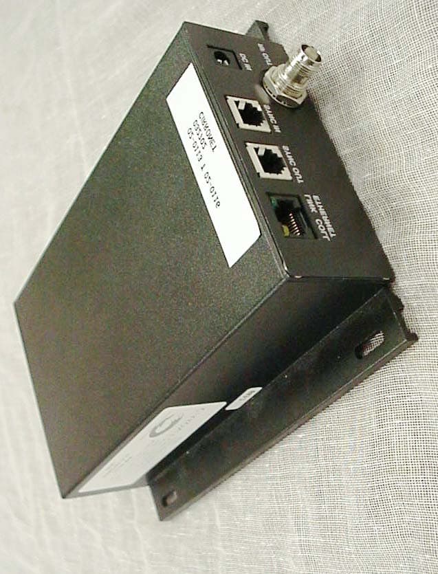
Click to zoom
Application Details
- Equipment Class
- DSS - Part 15 Spread Spectrum Transmitter
- Date of Grant
- Sep 23, 2002
- Application Purpose
- Original Equipment
- Date of Application
- Jul 08, 2002
- Equipment Note
- Data Transceiver
- Frequency Range
- 2401.69000000 - 2469.89000000
- Country
- United States
Documents & Files
Document Text
Text extracted from the exhibit documents filed with the FCC. Open a document above to read the original.
Users Manual
FCC ID: HSW-SEM2410 Cirronet Inc. will place the following statement in the front of each user/installers manual: Important Regulatory Information Cirronet Product FCCID: HSW-XXXX Fill in FCC ID number Note: This unit has been tested and found to comply with the limits for a class A digital device, pursuant to part 15 of the FCC Rules. These limits are designed to provide reasonable protection against harmful interference when the equipment is operated in a commercial environment. This equipment generates, uses, and can radiate radio frequency energy and, if not installed and used in accordance with the instruction manual, may cause harmful interference to radio communications. Operation of this equipment in a residential area is likely to cause harmful interference in which case the user will be required to correct the interference at their expense. FCC ID: HSW-SEM2410 In order to meet FCC s MPE requirements, Cirronet Corporation will add the following statements to the each users manual. It may be on the second page. Notice to users/installers using the 24 dBi parabolic dish antenna in conjunction with all Cirronet RF products. FCC rules limit the use of this antenna, when connected to Cirronet RF products for point-to-point applications only. It is the responsibility of the installer to ensure that the system is prohibited from being used in point-to-multipoint applications, omni- directional applications, and applications where there are multiple co-located intentional radiators transmitting the same information. Any other mode of operation using this antenna is forbidden. Information to user/installer regarding FCC s Maximum Permissible Exposure (MPE) limits. Notice to users/installers using the following fixed antennas, with Cirronet RF products: Andrews 24dBi parabolic dish, Andrews 18dBi parabolic dish, Cushcraft 15dBi Yagi, Mobile Mark 14dBi Corner Reflector, Mobile Mark 9dBi Corner Reflector The field strength radiated by any one of these antennas, when connected to Cirronet RF products, may exceed FCC mandated RF exposure limits. FCC rules require professional installation of these antennas in such a way that the general public will not be closer than 2 m from the radiating aperture of any of these antennas. End users of these systems must also be informed that RF exposure limits may be exceeded if personnel come closer than 2 m to the apertures of any of these antennas. Notice to users/installers using the following mobile antennas, with Cirronet RF products: Mobile Mark 12dBi omni-directional, Mobile Mark 9dBi omni-directional, MaxRad 5dBi whip, Cirronet Patch antenna, Ace 2dBi dipole, Mobile Mark 2dBi Stub The field strength radiated by any one of these antennas, when connected to Cirronet RF products, may exceed FCC mandated RF exposure limits. FCC rules require professional installation of these antennas in such a way that the general public will not be closer than 20 cm from the radiating aperture of any of these antennas. End users of these systems must also be informed that RF exposure limits may be exceeded if personnel come closer than 20 cm to the apertures of any of these antennas.
Users Manual
SEM 2410 Wireless Ethernet Modem/Bridge User’s Manual Augest 30, 2002 5375 Oakbrook Parkway Norcross, Georgia 30093 www.cirronet.com + 1 (678) 684-2000 Important Regulatory Information Cirronet Product FCCID: HSW-SEM2410 Maximum Permissible Exposure (MPE) Limits • Notice to users/installers using the 24 dBi parabolic dish antenna in conjunction with all Cirronet RF products. FCC rules limit the use of this antenna, when connected to Cirronet RF products for point-to-point applications only. It is the responsibility of the installer to ensure that the system is prohibited from being used in point-to-multipoint applications, omni-directional applications, and applications where there are multiple co-located intentional radiators transmitting the same information. Any other mode of operation using this antenna is forbidden. • Information to user/installer regarding FCC s Maximum Permissible Exposure (MPE) limits. • Notice to users/installers using the following fixed antennas, with Cirronet RF products: Andrews 24dBi parabolic dish, Andrews 18dBi parabolic dish, Cushcraft 15dBi Yagi, Mobile Mark 14dBi Corner Reflector, Mobile Mark 9dBi Corner Reflector The field strength radiated by any one of these antennas, when connected to Cirronet RF products, may exceed FCC mandated RF exposure limits. FCC rules require Note: This unit has been tested and found to comply with the limits for a class A digital device, pursuant to part 15 of the FCC Rules. These limits are designed to provide reasonable protection against harmful interference when the equipment is operated in a commercial environment. This equipment generates, uses, and can radiate radio frequency energy and, if not installed and used in accordance with the instruction manual, may cause harmful interference to radio communications. Operation of this equipment in a residential area is likely to cause harmful interference in which case the user will be required to correct the interference at their expense. professional installation of these antennas in such a way that the general public will not be closer than 2 m from the radiating aperture of any of these antennas. End users of these systems must also be informed that RF exposure limits may be exceeded if personnel come closer than 2 m to the apertures of any of these antennas. • Notice to users/installers using the following mobile antennas, with Cirronet RF products: Mobile Mark 12dBi omni-directional, Mobile Mark 9dBi omni-directional, MaxRad 5dBi whip, Cirronet Patch antenna, Ace 2dBi dipole, Mobile Mark 2dBi Stub The field strength radiated by any one of these antennas, when connected to Cirronet RF products, may exceed FCC mandated RF exposure limits. FCC rules require professional installation of these antennas in such a way that the general public will not be closer than 20 cm from the radiating aperture of any of these antennas. End users of these systems must also be informed that RF exposure limits may be exceeded if personnel come closer than 20 cm to the apertures of any of these antennas. End of Regulatory Information Table of Contents Introduction ...........................................................................................................1 Getting Started......................................................................................................2 Connecting the SEM..........................................................................................2 SEM Status Indicators .......................................................................................3 Configuring the SEM..........................................................................................3 SEM Operation .....................................................................................................6 Overview ............................................................................................................6 Point-to-Point Mode ...........................................................................................6 Point-to-Mulitpoint Mode ....................................................................................6 TCP/IP Addresses ................................................................................................8 BOOTP ..............................................................................................................8 DHCP.................................................................................................................9 SEM Command Set ............................................................................................10 Ethernet Commands ........................................................................................10 SEM/Radio Commands...................................................................................11 SEM System Commands.................................................................................13 Radio Modem Configuration ...............................................................................14 Radio Commands ............................................................................................14 Distance Optimization ......................................................................................15 Specifications......................................................................................................17 Radio Specifications ........................................................................................17 Connectors ......................................................................................................17 Indicators .........................................................................................................17 Power...............................................................................................................17 Troubleshooting ..................................................................................................18 Technical Support..................................…
Text truncated - open the document above for the full version.
Cover Letter(s)
FCC ID: HSW-SEM2410
Cover Letter(s)
FCC ID: HSW-SEM2410
Cover Letter(s)
July 18, 2002 Federal Communications Commission Equipment Authorization Division 7435 Oakland Mills Road Columbia, MD 21046 Dear Sirs, The application for FCC ID: HSW-SEM2410 was submitted on behalf of Cirronet. Upon filing out the 730 form, we mistakenly entered the FCC ID: HSW-SEM2400. Please correct the ID number to be FCC ID: HSW-SEM2410. We apologize for any inconvenience. If you have any further questions, please feel free to contact me at (770)741-0717. Sincerely, Timothy R. Johnson Engineering Manager
External Photos
FCC ID: HSW-SEM2410 Photo 1.EUT, Front View FCC ID: HSW-SEM2410 Photo 2.EUT, Rear View FCC ID: HSW-SEM2410 Photo 3.EUT, View Showing Connectors FCC ID: HSW-SEM2410 Photo 4.EUT, Top View of PCB
ID Label/Location Info
FCC ID: HSW-SEM2410
Internal Photos
FCC ID: HSW-SEM2410 Photo 4.EUT, Top View of PCB FCC ID: HSW-SEM2410 Photo 5.EUT, Bottom View of PCB FCC ID: HSW-SEM2410 Photo 6.Modular Transceiver, 3 Dimensional Front View FCC ID: HSW-SEM2410 Photo 7.Modular Transceiver, 3 Dimensional Rear View FCC ID: HSW-SEM2410 Photo 8.Modular Transceiver, Top View with Cover Opened FCC ID: HSW-SEM2410 Photo 9.Modular Transceiver, Top View of Board FCC ID: HSW-SEM2410 Photo 10.Modular Transceiver, Bottom View of Board
RF Exposure Info
FCC ID: HSW-SEM2410 5.1 RF Safety Requirements to 2.1091 for Mobile Transmitters The unit under evaluation has various external antennas. Cirronet Corporation calculated the MPE emission values for a SEM2410 with each of the antennas. The maximum power density occurs when using the 24 dBi dish for fixed applications and with the 12 dBi omnidirectional for mobile applications. They used the formula shown in OET Bulletin 65 and calculated the minimum distance between antenna and unsuspecting user as 26.0 cm for fixed applications and 6.5 cm for mobile applications. Cirronet Corporation will sell the SEM2410 with one of the following antennas: Previously Approved Antennas as Listed in Original Submittal MANUFACTURERTYPE OF ANTENNAMODELGAIN dB ACE DipoleACE-2400NF 2 dBi Cushcraft Yagi PC2415-RTNF15 dBi Mobile Mark Omni-Directional OD6-2400-RTNC6 dBi Mobile Mark Omni-Directional OD12-2400PTA-RTNC12 dBi Mobile Mark Corner Reflector SCR14-2400PTA-RTNC14 dBi Mobile Mark Patch P7-2400RTNC7 dBi Cirronet Corporation. Patch PA2410Appx. 3 dBi New Additional Antennas Covered by Permissive Change Application MANUFACTURERTYPE OF ANTENNAMODELGAIN dB Mobile Mark Vehicle MountRM3-2400-RTNC 2.5 dBi Mobile Mark Corner ReflectorSCR9-2400-RN 9 dBi MaxRad Whip MUF24005-RTNC5 dBi Andrews Parabolic Dish 26T-2400 A24 dBi Andrews Parabolic Dish 18T-2400 A18 dBi FCC ID: HSW-SEM2410 5.1 RF Safety Requirements to 2.1091 for Mobile Transmitters – Cont. Power Output The EUT’s maximum expected output power as shown in the original grant of certification (FCC ID: HSW-2410M) was Frequency of Fundamental (MHz) Measurement (dBm)* Measurement (Watt)* FCC Limit* (Watt) 2401.916.20.0411.0 2440.016.80.0471.0 2483.516.80.0471.0 * Measurement includes 0.3 dB for cable loss The maximum EIRP expected for fixed installations is with the +24 dBi gain parabolic dish antenna. This would yield and maximum EIRP of 16.8 dBm + 24 dBi = +40.8 dBm. The maximum EIRP expected for mobile installations is with the +12 dBi gain omnidirectional antenna. This would yield and maximum EIRP of 16.8 dBm + 12 dBi = +28.8 dBm. FCC ID: HSW-SEM2410 5.1 RF Safety Requirements to 2.1091 for Mobile Transmitters – Cont. Source Based Time Averaging Additionally, source based time averaging may be applied as the worse case transmit duty cycle is given as follows: Worst Case Transmit Duty Cycle for SEM2410 This factor was calculated by first determining the worst case scenario for system operation - worst case being defined as the scenario when the SEM2410 would be transmitting the longest period during a dwell. This worst case operating scenario is as follows: 1)point-to-point operation (only two units communicating with one another) 2)data flow is almost completely unidirectional (that is, one radio is relaying a large amount of data to the other radio with only synchronization data being passed back the other direction) 3)The amount of data being fed to the sending radio is exactly portioned out to fit the maximum packet size allowable (280 bytes). The radio cannot send more than 280 bytes on a single channel – additional data must be sent on the next hop. For this example, a remote unit is transferring a large data file to a base unit. The maximum transmit time by Remote on a single channel would be: = 280 bytes * 8 bits/byte * (1/460.8 Kbps) = 4.86 ms The minimum hop duration for this scenario would be 6.94 ms. This transmit pattern would continue on each channel and is considered repetitive. Therefore, for purposes of MPE, the transmission duty cycle correction factor is then calculated as: Duty cycle = (on time)/(total time) = 4.86/6.94 = 70.0 % This yields for a duty cycle correction of 10 log (0.70) = -1.5 dB. Therefore the maximum EIRP for fixed installations may be expected to be +40.8 dBm – 1.5 dB = +39.3 dBm Antilog(39.3 dBm/10) = 8511.4 mW The maximum EIRP for mobile installations may be expected to be +28.8 dBm – 1.5 dB = +27.3 dBm Antilog(27.3 dBm/10) = 537.0 mW 5.1 RF Safety Requirements to 2.1091 for Mobile Transmitters – Cont. FCC ID: HSW-SEM2410 MPE Calculations The limits for this unit (uncontrolled exposure) are 1.0 mW/cm 2 . Taking the RF Denisty Field Equation: S = (EIRP in mW)/(4πR 2 ) and solving for Distance R R = SQRT ((EIRP in mW)/(S4π)) Solving the above equation yields R (cm) = SQRT (8511.4(mw)/(1.0(mW/cm 2 )*4*π)) = 26.0 cm for fixed installations R (cm) = SQRT (537.0(mw)/(1.0(mW/cm 2 )*4*π)) = 6.5 cm for mobile installations Since the EUT is designed for mobile and fixed applications (where the expected separation distance between antenna and humans is greater than 20 cm or 2 m respectively), all manual instructions have specified 20 cm or 2 meters as appropriate for the types of antenna being used the minimum exposure distance.
Test Report
Digital Wireless Corporation FCC Part 15, Certification Application WIT2410 July 12, 1999 MEASUREMENT/TECHNICAL REPORT COMPANY NAME: Digital Wireless Corporation MODEL: WIT2410 FCC ID: HSW-2410M DATE:July 12, 1999 This report concerns (check one): Original grant X Class II change_____ Equipment type: Deferred grant requested per 47 CFR 0.457(d)(1)(ii)? yes_____ No X If yes, defer until:_________________ date N.A. agrees to notify the Commission by N.A. date of the intended date of announcement of the product so that the grant can be issued on that date. Report prepared by: United States Technologies, Inc. 3505 Francis Circle Alpharetta, GA 30004 Phone Number: (770) 740-0717 Fax Number: (770) 740-1508 FCC ID: HSW-2410M TABLE OF CONTENTS LETTER OF CONFIDENTIALITY SECTION 1 GENERAL INFORMATION 1.1 Product Description 1.2 Related Submittal(s) SECTION 2 TESTS AND MEASUREMENTS 2.1 Configuration of Tested EUT 2.2 Test Facility 2.3 Test Equipment 2.4 Modifications 2.5 Test Procedure and Results 2.6 Antenna Description 2.7 Peak Power (Antenna Conducted at Antenna Terminal) 2.8 Antenna Conducted Spurious Emissions 2.9 Peak Radiated Spurious Emissions 2.10 Average Radiated Spurious Emissions 2.11 Minimum 20 dB Bandwidth 2.12 Number of Hopping Channels 2.13 Average Time of Occupancy per Channel 2.14 Power Line Conducted Emissions for Transmitter 2.15 Radiated Emissions for Digital Device & Receiver (if Applicable) 2.16 Power Line Conducted for Digital Device & Receiver (if Applicable) SECTION 3 LABELING INFORMATION SECTION 4 BLOCK DIAGRAM(S)/ SCHEMATIC(S) SECTION 5 PHOTOGRAPHS SECTION 6 THEORY OF OPERATION SECTION 7 USER'S MANUAL FCC ID: HSW-2410M LIST OF FIGURES AND TABLES FIGURES 1)Test Configuration 2) Photograph(s) for Spurious and Conducted Emissions 3) Peak Output Power 4) Conducted Spurious Emissions 5) Peak Radiated Spurious Emissions 6) 20 dB Bandwidth 7) Number of Hopping Channels TABLES 1)EUT and Peripherals 2) Test Instruments 3) Peak Power Output 4) Peak Radiated Spurious Emissions 5) Average Radiated Spurious Emissions 6) 20 dB Bandwidth 7) Number of Hopping Channels 8) Conducted Emissions 9) Radiated Emissions for Digital Device and Receiver FCC ID: HSW-2410M SECTION 1 GENERAL INFORMATION FCC ID: HSW-2410M GENERAL INFORMATION 1.1Product Description The Equipment Under Test (EUT) is a Digital Wireless Corporation, Model WIT2410 modular 2.4 GHz spread spectrum transceiver. The EUT will be used with one of seven different antennas. FCC ID: HSW-2410M 1.2Related Submittal(s)/Grant(s) The EUT will be used to send/receive data. The transceiver presented in this report will be used with other like transceivers: The EUT is subject to the following authorizations: a) Certification as a transceiver (modular approval) b) Verification as a digital device The information contained in this report is presented for the certification & verification authorization(s) for the EUT. The manufacturer desires to seek a modular approval on this device. FCC ID: HSW-2410M SECTION 2 TESTS AND MEASUREMENTS FCC ID: HSW-2410M TEST AND MEASUREMENTS 2.1 Configuration of Tested System The sample was tested per ANSI C63.4, Methods of Measurement from Low-Voltage Electrical and Electronic Equipment in the Range of 9 kHz to 40 GHz (1992). Conducted and radiated emissions data were taken with the test receiver or spectrum analyzer's resolution bandwidth adjusted to 9 kHz and 120 kHz, respectively. All measurements are peak unless stated otherwise. The video filter associated with the spectrum analyzer was off throughout the evaluation process. Interconnecting cables were manipulated as necessary to maximize emissions. Interconnecting cables were manipulated as necessary to maximize emissions. A block diagram of the tested system is shown in Figure 1. Test configuration photographs for spurious and fundamental emissions are shown in Figure 2. The sample used for testing was received by U.S. Technologies on April 23 in good condition. 2.2 Test Facility Testing was performed at US Tech's measurement facility at 3505 Francis Circle, Alpharetta, GA. This site has been fully described and submitted to the FCC, and accepted in their letter marked 31040/SIT. Additionally this site has also been fully described and submitted to Industry Canada (IC), and has been approved under file number IC2982. 2.3 Test Equipment Table 2 describes test equipment used to evaluate this product. 2.4 Modifications No modifications were made by US Tech, to bring the EUT into compliance with FCC Part 15, Class B Limits for the transmitter portion of the EUT or the Class B Digital Device Requirements. FCC ID: HSW-2410M FIGURE 1 TEST CONFIGURATION EUT Antenna Controller AC Adapter Lap Top Computer 6’S 2 M U 120 VAC 60 Hz 2’ U Varied from 7” S to 4’ S 6’ U 120 VAC 60 Hz Direct Plug-in FCC ID: HSW-2410M Test Date:April 23, 1999 UST Project:99-317 Customer:Digital Wireless Corporation Model:WIT2410 FIGURE 2a Photograph(s) for Spurious and Fundamental Emissions (Ace Dipole) FCC ID: HSW-2410M Test Date:April 23, 1999 UST Project:99-317 Customer:Digital Wireless Corporation Model:WIT2410 FIGURE 2b Photograph(s) for Spurious and Fundamental Emissions (6 dBi Omni) FCC ID: HSW-2410M Test Date:April 23, 1999 UST Project:99-317 Customer:Digital Wireless Corporation Model:WIT2410 FIGURE 2c Photograph(s) for Spurious and Fundamental Emissions (12 dBi Omni) FCC ID: HSW-2410M Test Date:April 23, 1999 UST Project:99-317 Customer:Digital Wireless Corporation Model:WIT2410 FIGURE 2d Photograph(s) for Spurious and Fundamental Emissions (14 dBi Corner Reflector) FCC ID: HSW-2410M Test Date:April 23, 1999 UST Project:99-317 Customer:Digital Wireless Corporation Model:WIT2410 FIGURE 2e Photograph(s) for Spurious and Fundamental Emissions (DWC Patch) FCC ID: HSW-2410M Test Date:April 29, 1999 UST Project:99-317 Customer:Digital Wireless Corporation Model:WIT2410 FIGURE 2f Photograph(s) for Spurious and Fundamental Emissions (Mobile Mark Patch) FCC ID: HSW-2410M Test Date:April…
Text truncated - open the document above for the full version.
Test Report
February 21, 2001 Mr. Mark Tucker Cirronet Corporation 5375 Oakbrook Parkway Norcross, GA 30093 Dear Mr. Tucker: Enclosed please find Cirronet Corporation’s file copy of the Part 15 Class II Permissive Change Application for the WIT2410 Transceiver. Cirronet Corporation should expect to receive a certification grant for this product within the next 7-8 weeks. If you have any questions, please don't hesitate to call. Thank you for your business. Sincerely, Timothy R. Johnson NARTE Certified EMC Engineer No. EMC-002205-NE Cirronet Corporation FCC Part 15, Class II Permissive Change Application WIT2410 February 21, 2001 MEASUREMENT/TECHNICAL REPORT COMPANY NAME:Cirronet Corporation. MODEL: WIT2410 FCC ID:HSW-2410M DATE: February 21, 2001 This report concerns (check one): Original grant X Class II change_____ Equipment type: Modular Frequency Hopping Spread Spectrum Transceiver Deferred grant requested per 47 CFR 0.457(d)(1)(ii)? yes_____ No X If yes, defer until:_________________ date N.A. agrees to notify the Commission by N.A. date of the intended date of announcement of the product so that the grant can be issued on that date. Report prepared by: United States Technologies, Inc. 3505 Francis Circle Alpharetta, GA 30004 Phone Number: (770) 740-0717 Fax Number: (770) 740-1508 FCC ID: HSW-2410M TABLE OF CONTENTS SECTION 1 GENERAL INFORMATION 1.1 Product Description 1.2 Related Submittal(s) SECTION 2 TESTS AND MEASUREMENTS 2.1 Configuration of Tested EUT 2.2 Test Facility 2.3 Test Equipment 2.4 Modifications 2.5 Antenna Description 2.6 Peak Radiated Spurious Emissions 2.7 Average Radiated Spurious Emissions SECTION 3 PHOTOGRAPHS SECTION 4 USER'S MANUAL SECTION 5 RF EXPOSURE INFORMATION FCC ID: HSW-2410M LIST OF FIGURES AND TABLES FIGURES 1)Test Configuration 2) Photograph(s) for Spurious Emissions 3) Peak Radiated Spurious Emissions TABLES 1)EUT and Peripherals 2) Test Instruments 3) Peak Radiated Spurious Emissions 4) Average Radiated Spurious Emissions FCC ID: HSW-2410M SECTION 1 GENERAL INFORMATION FCC ID: HSW-2410M GENERAL INFORMATION 1.1Product Description The Equipment Under Test (EUT) is a Cirronet Corporation, Model WIT2410 modular 2.4 GHz spread spectrum modular transceiver. The EUT was originally approved for use with one of seven different antennas. The EUT was previously approved under FCC ID: HSW-2410M by the FCC on 10/6/99. Cirronet Corporation desires to add an additional 5 antennas to their original grant of certification. FCC ID: HSW-2410M 1.2Related Submittal(s)/Grant(s) The EUT was been previously approved under FCC ID: HSW-2410M by the FCC on 10/6/99. Additionally, the transceiver presented in this report will be used with other like transceivers. FCC ID: HSW-2410M SECTION 2 TESTS AND MEASUREMENTS FCC ID: HSW-2410M TEST AND MEASUREMENTS 2.1 Configuration of Tested System The sample was tested per ANSI C63.4, Methods of Measurement from Low-Voltage Electrical and Electronic Equipment in the Range of 9 kHz to 40 GHz (1992). Conducted and radiated emissions data were taken with the test receiver or spectrum analyzer's resolution bandwidth adjusted to 9 kHz and 120 kHz, respectively. All measurements are peak unless stated otherwise. The video filter associated with the spectrum analyzer was off throughout the evaluation process. Interconnecting cables were manipulated as necessary to maximize emissions. Interconnecting cables were manipulated as necessary to maximize emissions. A block diagram of the tested system is shown in Figure 1. Test configuration photographs for spurious and fundamental emissions are shown in Figure 2. The sample used for testing was received by U.S. Technologies on January 17, 2001 in good condition. The EUT was originally approved for use with one of seven different antennas. The EUT was previously approved under FCC ID: HSW-2410M by the FCC on 10/6/99. Cirronet Corporation desires to add an additional 5 antennas to their original grant of certification. Since the EUT has been previously tested and approved, only the spurious emissions test has been repeated. Additionally, since Cirronet Corporation desires to add two parabolic dish antennas (+18 dBi and +24 dBi), only the highest gain model was selected for test (+24 dBi). 2.2 Test Facility Testing was performed at US Tech's measurement facility at 3505 Francis Circle, Alpharetta, GA. This site has been fully described and submitted to the FCC, and accepted in their letter marked 31040/SIT. Additionally this site has also been fully described and submitted to Industry Canada (IC), and has been approved under file number IC2982. 2.3 Test Equipment Table 2 describes test equipment used to evaluate this product. 2.4 Modifications No modifications were made by US Tech, to bring the EUT into compliance with FCC Part 15, Class B Limits for the transmitter portion of the EUT. FCC ID: HSW-2410M FIGURE 1 TEST CONFIGURATION EUT Antenna Controller AC Adapter Laptop Computer 6’S 6’ U 120 VAC 60 Hz 1 m U Varied from 0.2 m to 1 m S 6’ U 120 VAC 60 Hz Direct Plug-in FCC ID: HSW-2410M Test Date:February 4, 2001 UST Project:01-0057 Customer:Cirronet Corporation Model:WIT2410 FIGURE 2a Photograph(s) for Spurious Emissions (2.5 dBi Vehicle Mount) FCC ID: HSW-2410M Test Date:February 4, 2001 UST Project:01-0057 Customer:Cirronet Corporation Model:WIT2410 FIGURE 2b Photograph(s) for Spurious Emissions (9 dBi Corner Reflector) FCC ID: HSW-2410M Test Date:February 4, 2001 UST Project:01-0057 Customer:Cirronet Corporation Model:WIT2410 FIGURE 2c Photograph(s) for Spurious Emissions (5 dBi Whip) FCC ID: HSW-2410M Test Date:February 4, 2001 UST Project:01-0057 Customer:Cirronet Corporation Model:WIT2410 FIGURE 2d Photograph(s) for Spurious Emissions (24 dBi Parabolic Dish) FCC ID: HSW-2410M TABLE 1 Test Date:February 4, 2001 UST Project:01-0057 Customer:Cirronet Corporation Model:WIT 2410M EUT and Peripherals PERIPHERAL MANU. MODEL NUMBER SERIAL NUMBER FCC ID:CABLES P/D (EUT) Cirronet Corporation WIT 2410M008517HSW-2410M1 …
Text truncated - open the document above for the full version.
Test Report
Cirronet Corporation FCC Part 15, Certification Application for the Model SEM2410 July 3, 2002 MEASUREMENT/TECHNICAL REPORT COMPANY NAME:Cirronet Corporation. MODEL: SEM2410 FCC ID:HSW-SEM2410 DATE: July 3, 2002 This report concerns (check one): Original grant X Class II change_____ Equipment type: Frequency Hopping Spread Spectrum Transceiver Deferred grant requested per 47 CFR 0.457(d)(1)(ii)? yes_____ No X If yes, defer until:_________________ date N.A. agrees to notify the Commission by N.A. date of the intended date of announcement of the product so that the grant can be issued on that date. Report prepared by: United States Technologies, Inc. 3505 Francis Circle Alpharetta, GA 30004 Phone Number: (770) 740-0717 Fax Number: (770) 740-1508 FCC ID: HSW-SEM2410 TABLE OF CONTENTS Agency Agreement Letter of Confidentiality SECTION 1 GENERAL INFORMATION 1.1 Product Description 1.2 Related Submittal(s) 1.3 Description of Information Provided 1.4 Copy of Name and Address Change 1.5 Professional Installation Justification SECTION 2 2.1 Test Report for the Original Part 15 Certification for the Modular Transceiver 2.2 Test Report for the Permissive Change Application for the Modular Transceiver 2.3 Test Report for Part 15 Class A Verification of the SEM2410 SECTION 3 LABELING INFORMATION SECTION 4 BLOCK DIAGRAM / SCHEMATIC OF TRANSCEIVER SECTION 5 PHOTOGRAPHS SECTION 6 THEORY OF OPERATION SECTION 7 USER'S MANUAL SECTION 8 RF EXPOSURE INFORMATION FCC ID: HSW-SEM2410 SECTION 1 GENERAL INFORMATION FCC ID: HSW-SEM2410 GENERAL INFORMATION 1.1Product Description The Equipment Under Test (EUT) is a Cirronet Corporation, Model SEM2410 transceiver which internally uses a modularly approved 2.4 GHz spread spectrum transceiver (HSW- 2410M). Since this device is typically professionally installed, this application is being submitted to certify the entire device (under a new ID number) in order to eliminate the need for non-standard connectors as allowed by 15.203. The SEM2410 is an industrial wireless modem housed in an environmentally rugged enclosure. The circuitry inside the modem includes a modularly approved WIT2410 frequency hopping transceiver (HSW-2410M), interface, and power conditioning circuitry. The SEM-2410 connects to the host through a standard Ethernet 10/100BaseT connection. A DB-9 serial port cable that attaches directly to the faceplate of the device is used to program internal module. Power is provided through a custom power connector. An antenna connector is also provided at the front of the unit. More detailed explanations of the function and use of the SEM-2410 can be found in the SEM product guide. 1.2Related Submittal(s)/Grant(s) The modular transceiver contained in this device has been previously approved under FCC ID: HSW-2410M by the FCC on 10/6/99 for use with seven different ant…
Text truncated - open the document above for the full version.
Contact Information
Applicant
Mark Tucker(Director of Hardware Engineering)
Technical Contact
U.S. TechnologiesTimothy Johnson
[email protected]770-740-0717
3505 Francis Circle · Alpharetta, Georgia · United States
Non-Technical Contact
U.S. TechnologiesTimothy Johnson
[email protected]770-740-0717
Test Firm
US TechSandy McEnery
Technical Specifications
| # | Rule Parts | Frequency Range | Power Output |
|---|---|---|---|
| 1 | 15C | 2.40 GHz - 2.47 GHz | 50.00 mW |
Other Applications from Murata Electronics North America
HSW2NR
May 13, 2026LBMA0ZZ2NR
Equipment Class
DTS - Digital Transmission SystemHSW2FR
Aug 29, 2024Communication Module
Equipment Class
DTS - Digital Transmission System
HSW2EG
Dec 14, 2022Type 2EG BLE Module
Equipment Class
DTS - Digital Transmission System
HSW-2420
Jul 12, 2021Wireless 2.4 GHz Industrial Transceiver
Equipment Class
DSS - Part 15 Spread Spectrum Transmitter
HSW-608B
Apr 11, 2021Wireless Medical Telemetry Service Radio Module
Equipment Class
TNB - Licensed Non-Broadcast Station Transmitter