HSW-Z2405HPAZigBee Modular Transmitter
Murata Electronics North America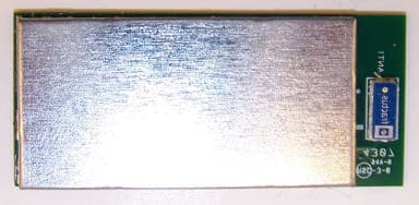
Click to zoom
Application Details
- Equipment Class
- DTS - Digital Transmission System
- Date of Grant
- Mar 26, 2008
- Application Purpose
- Original Equipment
- Date of Application
- Mar 24, 2008
- Equipment Note
- ZigBee Modular Transmitter
- Frequency Range
- 2405.00000000 - 2475.00000000
- Country
- United States
Documents & Files
Document Text
Text extracted from the exhibit documents filed with the FCC. Open a document above to read the original.
Users Manual
ZMN2405/ZMN2405HP/ ZMN2430/ZMN2430HP ZMN2430A/ZMN2430HPA Module Series ZigBee ® Module Developer’s Kit User’s Manual 3079 Premiere Pkwy Ste 140 Duluth, Georgia 30097 www.RFM.com +1 (678) 684-2000 Important Regulatory Information RFM Zigbee Series Regulatory Identification ZigBee Module FCC ID IC ID Type of Grant ZMN2405 HSW-ZMN2400 4492A-ZMN2400 Mobile ZMN2405HP HSW-Z2400HP 4492A-Z2400 Mobile ZMN2430 HSW-Z2430 4492A-Z2430 Mobile ZMN2430HP HSW-Z2430HP 4492A-Z2430HP Mobile ZMN2430A HSW-Z2430A 4492A-Z2430A Portable ZMN2430HPA HSW-Z2430HPA 4492A-Z2430HPA Portable THIS DEVICE COMPLIES WITH PART 15 OF THE FCC RULES. OPERATION IS SUBJECT TO THE FOLLOWING TWO CONDITIONS. (1) THIS DEVICE MAY NOT CAUSE HARMFUL INTERFERENCE, AND (2) THIS DEVICE MUST ACCEPT ANY INTERFERENCE RECEIVED, INCLUDING INTERFERENCE THAT MAY CAUSE UNDESIRED OPERATION. FCC User Information NOTE: This equipment has been tested and found to comply with the limits for a Class B digital device, pursuant to Part 15 of the FCC Rules. These limits are designed to provide reasonable protection against harmful interference in a residential installation. This equipment generates, uses, and can radiate radio frequency energy and, if not installed and used in accordance with the instructions, may cause harmful interference to radio communications. However, there is no guarantee that interference will not occur in a particular installation. If this equipment does cause harmful interference to radio or television reception, which can be determined by turning the equipment off and on, the user is encouraged to try to correct the interference by one or more of the following measures: • Reorient or relocate the receiving antenna. • Increase the separation between the equipment and receiver. • Connect the equipment into an outlet on a circuit different from that to which the receiver is connected. • Consult the dealer or an experienced radio/TV technician for help.” Warning: Changes or modifications to this device not expressly approved by RFM Inc. could void the user’s authority to operate the equipment. These devices can not be co-located with another transmitter without re-evaluation and separate FCC authorization. RF Exposure For ZigBee products with “Mobile Grants”. In accordance with FCC requirements of human exposure to radiofrequency fields, the radiating element shall be installed such that a minimum separation distance of 20 cm shall be maintained from the user and/or general population. Only antennas approved by the FCC for these modules may be used. Contact RFM for details. For ZigBee products with “Portable Grants”. In accordance with FCC requirements of human exposure to radiofrequency fields, the radiating element of there devices can be installed such that a separation distance of 2.5 cm or less can be maintained from the user and/or general population. (See Appendix 1 at the end of this document) These products have an intergraded antenna on the module which must not be removed. Industry Canada This Class B digital apparatus meets all requirements of the Canadian Interference Causing Equipment Regulations. Operation is subject to the following two conditions: (1)this device may not cause harmful interference, and (2) this device must accept any interference received, including interference that may cause undesired operation. Cet appareillage numérique de la classe B répond à toutes les exigences de l'interférence canadienne causant des règlements d'équipement. L'opération est sujette aux deux conditions suivantes: (1) ce dispositif peut ne pas causer l'interférence nocive, et (2) ce dispositif doit accepter n'importe quelle interférence reçue, y compris l'interférence qui peut causer l'opération peu désirée. Suggested End Product Labeling The final end product must be labeled in a visible area on the exterior of the enclosure with the following or similar text: “Contains TX FCC ID: (use correct ID from table above)” European Union All ZigBee modules conform to the requirements of ETSI EN 300 328 standard for radiated emissions. Table of Contents Regulatory Information ................................................................................................ 1. Introduction..............................................................................................................................1 2. ZigBee Networking...................................................................................................................2 2.1 Forming a Network...................................................................................................................3 2.2 Sleeping End Devices..............................................................................................................4 2.3 ZigBee Addressing...................................................................................................................4 2.4 Discovery..................................................................................................................................5 2.5 Network Topology and Size.....................................................................................................5 2.6 Static Network Addresses and Link Announcements.............................................................7 3. Getting Started.........................................................................................................................9 3.1 Installing ZBDemo....................................................................................................................9 3.2 Installing USB Drivers..............................................................................................................9 3.3 Running ZBDemo....................................................................................................................9 3.4 Communicating without ZBDemo..........................................................................................19 4. The Development Board.............…
Text truncated - open the document above for the full version.
Cover Letter(s)
Page 1 of 1 © Cirronet 2003 Cirronet, Inc. Tel: 678 684 2000 3079 Premiere Parkway Fax: 678 684 2001 Duluth, Georgia 30097 USA Date: 12/18/2007 Reference: FCC DA 00-1407 PART 15 UNLICENSED MODULAR TRANSMITTER APPROVAL Cirronet ZMN2405HPA ZigBee Module FCC ID: Z2405HPA Per FCC DA 00-1407, Cirronet’s ZigBee modules are compliance with the requirements listed below. 1. The modular transmitter must have its own RF shielding. Cirroent’s ZigBee Module has shielding as required. 2. The modular transmitter must have buffered modulation/data inputs. Cirroent’s ZigBee Module has buffered modulation and data inputs. 3. The modular transmitter must have its own power supply regulation. Cirronet’s ZigBee Module has its own internal regulator. 4. The modular transmitter must comply with the antenna requirements of Section 15.203 and 15.204(c). Cirronet’s ZigBee Module output is through a set of connections which are like a ball grid array and once soldered to a PC board the connects are not accessible. Without a support PC board the module is unusable. 5. The modular transmitter must be tested in a stand-alone configuration, i.e., the module must not be inside another device during testing. Cirronet’s ZigBee Module was tested on a support PC board designed to meet the requirements of modular approval. Complete open. 6. The modular transmitter must be labeled with its own FCC ID number Cirronet’s ZigBee Module is design as a OEM module. The ZigBee Module will be labeled and instructions given to the OEM customer for FCC label requirements. 7. The modular transmitter must comply with any specific rule or operating requirements applicable to the transmitter. An Integration Guide is provided with FCC compliance information. 8. The modular transmitter must comply with any applicable RF exposure requirements. An Integration Guide is also provides FCC MPE warnings per antenna types that are used. Al Patrick Sr. Compliance Engineer Cirronet Inc. 3079 Premiere Parkway, Suite 140 Duluth, GA 30097 USA TEL: 678 684 2000 FAX: 678 684 2001
Cover Letter(s)
US Tech FCC ID: HSW-Z2405HPA Test Report: FCC Spread Spectrum Radio Report Number: 07-0297 Issue Date: 13 February 2008 Customer: Cirronet, Inc. Model: ZMN2405HPA Page 6 of 49 Agency Agreement Federal Communications Commission P.O. Box 429 Columbia, MD 21045 Date: December 11, 2007 Gentlemen: I hereby appoint US Tech to act as our agent in the preparation of an application for equipment authorization of ZMN2405HPA, FCC ID: HSW-Z2405HPA under Part 15 of the FCC Rules and Regulations. I certify that the Exhibits properly describe the device or system for which authorization is sought, that the information described in the User's Manual will be provided with each item manufactured or distributed by the applicant, and that the labels described by Exhibit 3 will be affixed to each item manufactured or distributed by the applicant. I further certify that appropriate arrangements have been made to assure that production units of this equipment bearing the name and FCC IDENTIFIER listed in this application will continue to comply with the Commission's requirements. I further certify by signature below that no party (per 47 CFR 1.2002(b)) to the application is subject to a denial of Federal benefits, including FCC benefits, pursuant to Section 5301 of the Anti-Drug Abuse Act of 1988, 21 U.S.C. 853(a). This appointment also includes the authority to complete FCC Form 731 on our behalf and sign the application as an authorized agent. Al Patrick, Date: November 30, 2007 Sr. Compliance Engineer Al Patrick Cirronet Inc. [email protected] 3079 Premiere Parkway Duluth, GA 30097 678 684 2000 ext. 138
Cover Letter(s)
AGENCY AGREEMENT Federal Communications Commission Date: March 24, 2008 P.O. Box 429 Columbia, MD 21045 Gentlemen: By signature below, we hereby appoint Al Patrick to act as Cirronet’s agent with regard to all FCC equipment authorizations. This appointment will remain in effect until otherwise notified. I further certify by signature below that no party (per 47 CFR 1.2002(b)) to the application is subject to a denial of Federal benefits, including FCC benefits, pursuant to Section 5301 of the Anti-Drug Abuse Act of 1988, 21 U.S.C. 853(a). This appointment includes the authority to complete FCC Form 731 on our behalf and sign the application as an authorized agent. Name: Mark Tucker Signature: Title: V.P of Engineering Date: March 24, 2008
Cover Letter(s)
March 10, 2008 Richard Fabina Examining Engineer ATCBI RE: FCC ID: HSW-Z2405HPA & IC: 4492A-Z2405HPA for Cirronet, Inc. Response To Comments Dear Mr. Fabina: In response to your comments regarding the above referenced FCC ID: 1. “The block diagram for this device shows both a low and high power version of this device. Please be informed that two separate FCC and IC numbers must be filed to market a low and high power version of this device. Please confirm which version of the device is being approved via this application. Make sure all documentation submitted supports this version. YES, THERE IS A HIGH POWER AND A LOW POWER VERSION OF THIS DEVICE. SEPARATE APPLICATIONS FOR FCC AND IC HAVE BEEN FILED FOR EACH DEVICE. THIS APPLICATION IS FOR THE HIGH POWER VERSION (HPA). 2. “Mark Tucker is listed as the contact person for Cirronet, Inc. on the FCC Grantee Code Database. As such, he is the authorized person to sign letters for Cirronet. Unfortunately Al Patrick has signed the FCC agent letter and the FCC confidentiality request letter submitted with this application. Please either provide a letter from Mark Tucker giving Al Patrick the authority to sign these letter for Cirronet on this application or submit new letters signed by Mark Tucker for this application.” Mark Tucker is the President of Cirronet and typically does not sign these letters. Al Patrick is the Compliance Engineer in charge of the Product compliance and he has always signed these letters in the ½ dozen applications granted by ATCB in the last year, including the ones in the application granted through ATCB last week. May we continue to do this or should I tell ATCB that your policy has changed and trouble them to provide new letters? 3. “Please provide a schematic diagram and a parts list for this device....” Schematic Diagram and Parts list have been uploaded. 4. This application appears to be for a modular approval. As such, both and FCC cover letter and an IC cover letter exhibit must be submitted that request modular approval...” Modular Approval Letter has been uploaded. 5. “Please provide a completed and signed copy of Appendix A and B of RSS-102...” Appendix A and B uploaded. 6. “The model number shown on the IC application form (Z2405HPA) does not agree with the model number shown on the IC label and other supporting documentation (ZMN2405HPA). Please correct the incorrect exhibits. The IC label must display the model number in accordance with Section 5.2 of RSS-GEN” The Model Number on the IC application has been corrected and uploaded. 7. “Please correct the FCC application form to show DTS (Digital Transmission System) as the equipment code..... “ Form 731 has been corrected and uploaded. 8. “Please fill out the following items on the IC application form: .....” Items completed. 9. Please identify the FCC test procedure used for testing this DTS device in Section 2.1 of the test report.” Corrected Report uploaded. 10. “Please confirm that Table 3 contains AC line conducted test results for both transmit and receive modes for this device. Confirmed – Table 3 contains results for both transmit and receive modes. 11. Please provide a brief paragraph that describes the AC line conducted emissions test procedure. Corrected Report uploaded. 12. “Please provide a more detailed operation description or zero span plots showing pulsed emissions from this transmitter....” Plots provided. 13. “Please remove all references from the test report to Section 15.249 of the FCC Rules...” All references removed. 14. In Section 2.12 of the test report, please provide a brief paragraph that describes the radiated test procedure used for measuring emissions form this device. I’m looking for statements to be added to the test report that say the device was rotated 360 degrees, measurement antenna was located 3 meters from the device, it was also raised and lowered between 1 and 4 meters in height and both antenna polarities (H or V) were checked over 30 Mhz to 25 Ghz to maximize emissions from this device.” Corrected Report has been uploaded. 15. In Table 6 of the test report, please explain where the radiated emissions limits of 23174 and 19116 uV/m @ # meters come from......” Limits removed. 16. In accordance with Section 15.31 (m) of the FCC Rules and Section 4.3(g) of RSS-Gen, you must measure the low, middle and high channels of this device...” Corrected report uploaded. 17. Please redo your 6 dB bandwidth plots to show the total bandwidth with the delta marker function on the spectrum analyzer. You do not show the complete bandwidth in any submitted plot....” Re- measured and corrected report uploaded. 18. Please provide a brief paragraph that describes the radiated test procedure for output power measurements. Corrected report uploaded. 19. In Section 2.15 of the test report, it states the output power of this transmitter is set to + 16 dBm, but you only measure a maximum of 14.5 mW on one channel and less than 10 mW on the other two. Please explain this discrepancy.” DISCREPANCY EXPLAINED 20. The band edge compliance measurements in Section 2.17 were made with a RBW of 100 kHZ to show compliance to the 20 dB below carrier limits in 15.247(d).....” ADDRESSED 21. In Section 2.18 and Table 10 of the test report, please show all the correction factors and a sample calculation so I can verify the accuracy of the reported power spectral density levels.” Added and corrected report uploaded. 22. Your MPE calculations are Section 2.19 of the test report are incorrect....” Recalculated and corrected report uploaded. 23. The user manual should provide further information and better detail to the OEM as to how to use the modular transmitter in order to maintain the modular transmitter approval and RF exposure compliance. IN order to make sure that the integrators are given enough information, please provide a revised user manual where the following or similar information has been added to it:...” A revised manual has been uploaded. 24. F…
Text truncated - open the document above for the full version.
External Photos
US Tech FCC ID: HSW-Z2405HPA Test Report: FCC Spread Spectrum Radio Report Number: 07-0297 Issue Date: 13 February 2008 Customer: Cirronet, Inc. Model: ZMN2405HPA Page 42 of 49 5. Photographs Figure 14. ZMN2405HPA with Shield ZMN2405HPA
ID Label/Location Info
US Tech FCC ID: HSW-Z2405HPA Test Report: FCC Spread Spectrum Radio Report Number: 07-0297 Issue Date: 13 February 2008 Customer: Cirronet, Inc. Model: ZMN2405HPA Page 39 of 49 3. Labeling Information Figure 13. Label Placement
Internal Photos
US Tech FCC ID: HSW-Z2405HPA Test Report: FCC Spread Spectrum Radio Report Number: 07-0297 Issue Date: 13 February 2008 Customer: Cirronet, Inc. Model: ZMN2405HPA Page 43 of 49 5. Photographs (cont.) Figure 15. ZMN2405HPA Top and Bottom ZMN2405HPA Top ZMN2405HPA Bottom
RF Exposure Info
Confidential Page 1 3/10/2008 Appendix I Operating Scenario for ZMN2405HPA The ZMN2405HPA is used in a portable network application using Direct Sequence Spread Spectrum (DSSS) technology. The ZMN2405HPA is a ZigBee device utilizing IEEE 802.15.4 physical layer with propriety software to create network infrastructure that is decentralized and inexpensive, as each node need transmit only as far as the next node. Nodes act as repeaters to transmit data from nearby nodes to peers that are too far away to reach, resulting in a network that can span a large distance, especially over rough or difficult terrain. These products may be used as a portable, fixed or mobile devices. Maximum Transmit Duty Cycle Each remote ZMN2405HPA can transmit a maximum length of 2 ms in a 100 ms window. This is set by design and cannot be adjusted by the user. Therefore, our source-averaged transmit duty cycle becomes 0.2. Confidential Page 2 3/10/2008 Calculated Average Power The Power Threshold for ‘General Population’ portable designation without SAR testing is: (based on Oct 2005 TCB workshop PPT slide) (60 / F GHz ) mW for distances < 2.5 cm For the 2.4 GHz frequency band, this results in a limit of 25 mW. Note that we use the more restrictive “General Population” limit in this case even though the individuals using this product will certainly be aware of its function and would qualify under the ‘occupational’ category. Given the maximum transmit duty cycle specified in Appendix II, the average transmitted power of a ZMN2405HPA remote can be calculated as: Maximum Pout = 63 mW (18 dBm nominal) Maximum Antenna Gain = 0 dBi (for portable use) Maximum Transmit Duty cycle (per above) = 0.2 Pave (Source-based average) = 0.063 * 0.2 = 12.6 mW Conclusion: The ZMN2405HPA meets the MPE limits for a ‘Portable’ device operating in the ‘General Population’.
Test Report
Page 1 of 103 Application for Cirronet, Incorporated FCC Part 15, Certification For the ZMN2405HPA FCC ID: HSW-Z2405HPA UST Project: 07-0297 Issue Date: February 13, 2008 3505 Francis Circle Alpharetta, GA 30004 PH: 770-740-0717 Fax: 770-740-1508 www.ustech-lab.com Page 2 of 103 I certify that I am authorized to sign for the manufacturer and that all of the statements in this report and in the Exhibits attached hereto are true and correct to the best of my knowledge and belief: US Tech (AGENT RESPONSIBLE FOR TEST): By: Name: Alan Ghasiani Title: Operations & Engineering Date: February 13, 2008 Cirronet, Incorporated 3079 Premiere Parkway Duluth, GA 30097 By: Name: Title: Date: This report shall not be reproduced except in full. This report may be copied in part only with the prior written approval of US Tech. The results contained in this report are subject to the adequacy and representative character of the sample provided. 3505 Francis Circle Alpharetta, GA 30004 PH: 770-740-0717 Fax: 770-740-1508 www.ustech-lab.com US TECH FCC ID: HSW-Z2405HPA Test Report: FCC Spread Spectrum Radio Report Number: 07-0297 Issue Date: 13 February 2008 Customer: Cirronet, Inc. Model: ZMN2405HPA Page 3 of 103 MEASUREMENT/TECHNICAL REPORT COMPANY NAME: Cirronet, Incorporated MODEL: ZMN2405HPA FCC ID: HSW- Z2405HPA DATE: February 13, 2008 This report concerns (check one): Original grant X Class II change_____ Equipment type: 2.4 GHz Zigbee Radio Deferred grant requested per 47 CFR 0.457(d)(1)(ii)? yes_____ No X If yes, defer until:_________________ date N.A. agrees to notify the Commission by N.A. date of the intended date of announcement of the product so that the grant can be issued on that date. Report prepared by: US Tech 3505 Francis Circle Alpharetta, GA 30004 Phone Number: (770) 740-0717 Fax Number: (770) 740-1508 US Tech FCC ID: HSW-Z2405HPA Test Report: FCC Spread Spectrum Radio Report Number: 07-0297 Issue Date: 13 February 2008 Customer: Cirronet, Inc. Model: ZMN2405HPA Page 4 of 103 Table Of Contents Paragraph Title Page Agency Agreement 6 Confidentiality 7 1. General Information 8 1.1 Product Description 8 1.2 Related Submittal(s) 8 2. Tests and Measurements 9 2.1 Configuration of Tested EUT 9 2.2 Test Facility 9 2.3 Test Equipment 9 2.4 Modifications 9 2.5 Number of Operating Frequencies (CFR 15.31(m)) 16 2.6 Peak Limits for signals above 1000 MHz (CFR 15.35) 16 2.7 Antenna Description (CFR 15.203) 16 2.8 Power line Conducted Emissions for Digital Peripherals and Receivers 17 (CFR 15.107) 2.9 Power line Conducted Emissions for Transmitter (CFR 15.207) 18 2.10 Worst Case Transmit Duty Cycle 18 2.11 Radiated Emissions Measurement for Digital Peripherals and Receivers 19 (CFR 109) 2.12 Radiated Emissions for Spurious and Harmonics (CFR 15.209) 20 2.13 Restricted Bands (CFR 15.205) 23 2.14 Minimum Six (6) dB Band width (CFR15.247 (a) (2)) 23 2.15 Peak Power Output (CFR 15.247 (b) (3)) 27 2.16 Directional Antenna with gains greater than 6 dB i (CFR 15.247 (c)) 32 2.17 Band Edge Requirement (CFR 15.247 (d)) 33 2.18 Power Spectral Density (CFR 15.247 (e) 36 2.19 Maximum Public Exposure to RF Radiation (CFR 15.247 (i) 38 3. Labeling Information 39 4. Block Diagram(s)/ Schematic(s) 40 5. Photographs 42 6. Theory of Operation 44 7. User's Manual 45 US Tech FCC ID: HSW-Z2405HPA Test Report: FCC Spread Spectrum Radio Report Number: 07-0297 Issue Date: 13 February 2008 Customer: Cirronet, Inc. Model: ZMN2405HPA Page 5 of 103 List Of Figures Figure Title Page 1 Test Configuration 10 2 Photograph of Fundamental and Spurious Emissions Measurement 12 (Front View) 3 Photograph of Fundamental and Spurious Emissions Measurement 13 (Front View) 4 Photograph of Conducted Emissions Measurement 14 5 Pulsed Timing 18 5 Minimum Six dB bandwidth Section 15.247 (a)(2) – Low 24 6 Minimum Six dB Bandwidth Section 15.247 (a)(2) - Mid 25 7 Minimum Six dB Bandwidth Section 15.247 (a)(2) – High 26 8 Peak Power per FCC Section 15.247 (b) Low Channel 29 9 Peak Power per FCC Section 15.247 (b) Mid Channel 30 10 Peak Power per FCC Section 15.247 (b) High Channel 31 11 Band Edge per FCC Section 15.247 (a)(1)(iii) High 34 12 Band edge per FCC Section 15.247 (a)(1)(iii) Low 35 13 Label Placement 39 14 Photograph of ZMN2405HPA with Shield 42 15 Photograph of ZMN2405HPA with Shields Removed 43 List Of Tables Table Title Page 1 EUT and Peripherals 11 2 Test Instruments 15 3 Antenna(s) Supplied with EUT 16 4 Conducted Emissions Test Data 17 5 Radiated Emissions Data (Digital Device and Receiver) 19 6 Peak Radiated Emissions 21 7 Average Radiated Emissions 22 8 Six (6) dB Bandwidth 23 9 Radiated Peak Power Output 28 10 Peak Power Spectral Density 37 US Tech FCC ID: HSW-Z2405HPA Test Report: FCC Spread Spectrum Radio Report Number: 07-0297 Issue Date: 13 February 2008 Customer: Cirronet, Inc. Model: ZMN2405HPA Page 8 of 103 1. General Information 1.1 Product Description The Equipment Under Test (EUT) is a Cirronet, Incorporated, Model ZMN2405HPA High Power modular 2.4 GHz Spread Spectrum Transceiver. The EUT will be used with an integrated antenna. 1.2 Related Submittal(s)/Grant(s) The EUT will be used to send/receive data. The transceiver presented in this report will be used with other like transceivers: The EUT is subject to the following authorizations: a) Certification as a transceiver (modular approval) b) Verification as a digital device The information contained in this report is presented for the certification & verification authorization(s) for the EUT. The manufacturer desires to seek a modular approval on this device. 2. Tests and Measurements 2.1 Configuration of Tested System The EUT’s antenna is not removable, therefore all measurements are performed using radiated techniques. The test sample was tested per ANSI C63.4, Methods of Measurement from Low-Voltage Electrical and Electronic Equipment in the Range of 9 kHz to 40 GHz (2003), FCC KDB Publication Number 558074, FCC DA 00- 705. Conducted and radiated emissions data belo…
Text truncated - open the document above for the full version.
Test Setup Photos
US Tech FCC ID: HSW-Z2405HPA Test Report: FCC Spread Spectrum Radio Report Number: 07-0297 Issue Date: 13 February 2008 Customer: Cirronet, Inc. Model: ZMN2405HPA Page 12 of 49 Figure 2. Photograph(s) of Fundamental and Spurious Emissions Measurement (Front View) US Tech FCC ID: HSW-Z2405HPA Test Report: FCC Spread Spectrum Radio Report Number: 07-0297 Issue Date: 13 February 2008 Customer: Cirronet, Inc. Model: ZMN2405HPA Page 13 of 49 Figure 3. Photograph(s) of Fundamental and Spurious Radiated Emissions Measurement (Rear View) US Tech FCC ID: HSW-Z2405HPA Test Report: FCC Spread Spectrum Radio Report Number: 07-0297 Issue Date: 13 February 2008 Customer: Cirronet, Inc. Model: ZMN2405HPA Page 14 of 49 Figure 4. Photograph of Conducted Emissions Measurement US Tech FCC ID: HSW-Z2405HPA Test Report: FCC Spread Spectrum Radio Report Number: 07-0297 Issue Date: 13 February 2008 Customer: Cirronet, Inc. Model: ZMN2405HPA Page 15 of 49 Table 2. Test Instruments EQUIPMENT MODEL NUMBER MANUFACTURER SERIAL NUMBER DATE OF LAST CALIBRATION SPECTRUM ANALYZER 8566B HEWLETT-PACKARD 2332A10055 1/10/08 SPECTRUM ANALYZER 8593E HEWLETT-PACKARD 3205A00124 7/16/07 SIGNAL GENERATOR 8648B HEWLETT-PACKARD 3642U01679 10/30/07 RF PREAMP 8447D HEWLETT-PACKARD 2944A06291 6/14/07 BICONICAL ANTENNA 3110B EMCO 9307-1431 11/15/07 LOG PERIODIC 3146 EMCO 3110-3236 11/21/07 LISN (x 2) 8028-50-TS24-BNC 8028 SOLAR ELE. 910494 & 910495 5/10/07 HORN ANTENNA 3115 EMCO 9107-3723 10/16/06 2 yr. PREAMP 8449B HEWLETT PACKARD 3008A00480 8/21/07 CALCULATION PROGRAM N/A N/A Ver. 6.0 N/A
Contact Information
Applicant
Mark Tucker(Director of Hardware Engineering)
Technical Contact
United States Techonlogies, Inc.Stephen Sawyer
[email protected]770-740-0717
3505 Francis Circle · Alpharetta, Georgia · United States
Test Firm
US TechGeorge Yang
Technical Specifications
| # | Rule Parts | Frequency Range | Power Output |
|---|---|---|---|
| 1 | 15C | 2.40 GHz - 2.48 GHz | 14.50 mW |
Other Applications from Murata Electronics North America
HSW2NR
May 13, 2026LBMA0ZZ2NR
Equipment Class
DTS - Digital Transmission SystemHSW2FR
Aug 29, 2024Communication Module
Equipment Class
DTS - Digital Transmission System
HSW2EG
Dec 14, 2022Type 2EG BLE Module
Equipment Class
DTS - Digital Transmission System
HSW-2420
Jul 12, 2021Wireless 2.4 GHz Industrial Transceiver
Equipment Class
DSS - Part 15 Spread Spectrum Transmitter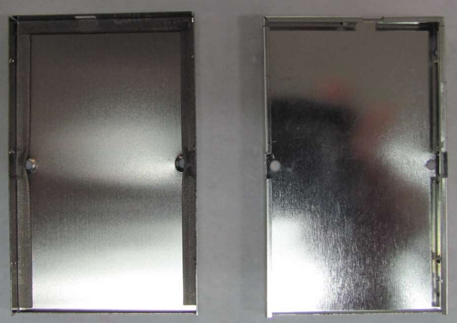
HSW-608B
Apr 11, 2021Wireless Medical Telemetry Service Radio Module
Equipment Class
TNB - Licensed Non-Broadcast Station Transmitter