HV4DTI520LCD Tablet
Wacom Co Ltd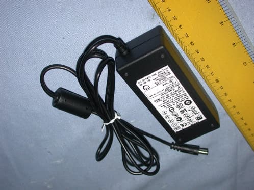
Click to zoom
Application Details
- Equipment Class
- DCD - Part 15 Low Power Transmitter Below 1705 kHz
- Date of Grant
- Dec 16, 2004
- Application Purpose
- Original Equipment
- Date of Application
- Dec 16, 2004
- Equipment Note
- LCD Tablet
- Frequency Range
- 0.59975000 - 0.59975000
- Company
- Wacom Co Ltd
- Country
- Japan
Documents & Files
Document Text
Text extracted from the exhibit documents filed with the FCC. Open a document above to read the original.
Users Manual
1 Introduction and Overview The Wacom® DTI-520™ Interactive Pen Display combines an LCD monitor with a Wacom tablet. This gives you a direct point-and-draw-on-screen interface that can be used with a Personal Computer (PC) or Macintosh computer. DTI-520's basic components include a Wacom tablet internally mounted behind a 15.0" diagonal TFT color LCD monitor, and Wacom's pen. Your DTI-520 Interactive Pen Display offers a number of significant advantages over a standard monitor: ■ Reduced power consumption ■ Reduced heat generation ■ Requires less work space ■ Flicker free and easier on the eyes ■ Integrated input and display ■ Pressure-sensitive drawing directly on the display screen. This manual describes how to install DTI-520 hardware and software. It also describes how to use DTI-520 and the pen. Note that the computer treats the two parts of DTI-520 (the LCD monitor and the Wacom tablet) as separate pieces of hardware. Therefore, the installation process is completed in two stages. First, you will install the LCD monitor portion of DTI-520. In the second stage you will install DTI-520's tablet functionality. You can find information on using the Wacom Tablet Control Panel for customizing your tablet and pen settings in the online Help, located under the Help menu in the Wacom Tablet Control Panel. The following are not included with this product: ■ Information about your specific computer hardware ■ Information about your operating system ■ Information about application software. Please refer also to your computer hardware, operating system, or software application manuals. To use the pressure-sensitivity of the pen with your favorite drawing application, refer to instructions in that application's manuals. English 2 CAUTION WARNING Do not use DTI-520 Interactive Pen Display in a facility control system that requires extremely high reliability; it may cause other electronic devices to malfunction, or other devices may cause DTI-520 to malfunction. Where use is prohibited, power off DTI-520 to prevent the possibility of it causing other electronic devices to malfunction. Wacom does not accept any liability for direct or consequential damages. For details, please refer to your Warranty, located at the inside back cover of this manual. Only use the AC adaptor that came with DTI-520. If a different type of AC adaptor is used, DTI-520 will not work properly or it may be damaged. Using a different type of AC adaptor also has the potential to result in fire. Use of a different AC adaptor will void your warranty. If the LCD screen has been damaged, DO NOT touch any liquid that may be leaking from it; this liquid is an irritant. In case of contact with skin, eyes, or mouth, rinse immediately with running water for at least 15 minutes or more. If contact is made with the eyes or mouth, also consult a physician. Prevent your children from swallowing the pen nib or side switch knob. The pen nib or side switch knob may accidentally be pulled out if children are biting on them. HIGH VOLTAGE . Do not open DTI-520. It has the risk of electric shock. Precautions on Use and Handling Be sure to follow all instructions, cautions, and warnings found within this manual. Failure to do so could cause the loss of data or damege of your computer. Failure to do so could also void your warranty, in which case Wacom shall have no responsibility for such loss or damage and to repair or replace the product. When adjusting the tilt angle of DTI-520, be careful to avoid catching your finger in the gap of the movable portion of the stand. Be sure to use a grounded power source when applying power to DTI-520. Do not lift DTI-520 by the stand; this may damage the stand mechanism. When lifting or moving DTI-520, always do so by grasping the main body casing. 3 Do not put heavy articles on DTI-520; this may damage the display screen or stand. Do not place heavy article on DTI-520 cabling, repeatedly bend the cables, or apply heavy stress on the cable connectors; this may damage the unit or your cabling. CAUTION This product is for use with a VGA graphics card; using an inappropriate graphics card may damage DTI-520. Do not connect or disconnect the DVI video cable or power cable while DTI-520 and your computer is turned on; it may damage the LCD display or computer video card. Do not disassemble DTI-520 or pen. This may cause DTI-520 or pen to malfunction. In this case, Wacom shall have no responsibility to repair or replace the product. Do not use or store DTI-520 where: - Temperature changes are severe (e.g., outdoors or inside a vehicle). - DTI-520 and pen are exposed to direct sunlight or heat from a heating appliance. - DTI-520 and pen are exposed to water or any other kind of liquid. - Temperature or humidity exceeds the specifications. Do not block the ventilation holes in the rear panel; this may overheat and damage DTI-520. Do not use DTI-520 in a dusty environment; It may damage the unit. Do not scratch the cover glass of DTI-520. Avoid placing sharp objects on the glass surface. Do not use detergent to clean the cover glass of DTI-520; this may alter the surface friction and deteriorate the handwriting feel. 4 Table of Contents Introduction and Overview .............................................................1 Precautions on Use and Handling .................................................2 Table of Contents ..........................................................................4 Checking Packed Components ...................................................5 Connect DTI-520 to a computer .................................................6 Tablet Driver Installation ..............................................................8 Uninstalling The DTI-520 ...............................................................9 Customizing The DTI-520 – The Basics ...............................................10 Opening the Wacom Tablet Control Panel Control Panel Basics Control Panel Details Calibrating the DTI…
Text truncated - open the document above for the full version.
Block Diagram
DC12V (No battery, no oscillator) ANALOG CONNECTOR Analog RGB Signal Gm5221 X'tal + 5V522V REGULATOR BACK LIGHT INVERTER 63.3kHz DC/DC CONVERTER 150kHz AC ADAPTER CONNECTOR LCD UNIT BACK LIGHT SENSOR STYLUS 600.0kHz < DTF-520 Block Diagram > X’ tal 6MHz AC ADAPTER INPUT:AC100 ~ 240V 50 ~ 60Hz SENSOR I/F 14.318MHz Flash memory +3.3V+1.8V CPU (12MHz) USB CONNECTOR CPU ANALOG IC COMPOSITE VIDEO CONNECTOR Composite Video Signal VIDEO DECODER TW9905 X'tal 27MHz +3.3V + 5V USB HUB X'tal 12MHz SERIAL CONNECTOR CPU X’ tal 4MHz
External Photos
Spectrum Research & Testing Lab., Inc. No. 101-10, Ling 8, Shan-Tong Li, Chung-Li City, Taoyuan, Taiwan Tel: 886-3-4987684 Fax: 886-3-4986528 Photo Page: 1 of 10 Part I: Monitor PHOTOS OF EUT Spectrum Research & Testing Lab., Inc. No. 101-10, Ling 8, Shan-Tong Li, Chung-Li City, Taoyuan, Taiwan Tel: 886-3-4987684 Fax: 886-3-4986528 Photo Page: 2 of 10 PHOTOS OF EUT Spectrum Research & Testing Lab., Inc. No. 101-10, Ling 8, Shan-Tong Li, Chung-Li City, Taoyuan, Taiwan Tel: 886-3-4987684 Fax: 886-3-4986528 Photo Page: 3 of 10 PHOTOS OF EUT Spectrum Research & Testing Lab., Inc. No. 101-10, Ling 8, Shan-Tong Li, Chung-Li City, Taoyuan, Taiwan Tel: 886-3-4987684 Fax: 886-3-4986528 Photo Page: 4 of 10 PHOTOS OF EUT Spectrum Research & Testing Lab., Inc. No. 101-10, Ling 8, Shan-Tong Li, Chung-Li City, Taoyuan, Taiwan Tel: 886-3-4987684 Fax: 886-3-4986528 Photo Page: 5 of 10 PHOTOS OF EUT Spectrum Research & Testing Lab., Inc. No. 101-10, Ling 8, Shan-Tong Li, Chung-Li City, Taoyuan, Taiwan Tel: 886-3-4987684 Fax: 886-3-4986528 Photo Page: 6 of 10 Part II: Pen PHOTOS OF EUT Spectrum Research & Testing Lab., Inc. No. 101-10, Ling 8, Shan-Tong Li, Chung-Li City, Taoyuan, Taiwan Tel: 886-3-4987684 Fax: 886-3-4986528 Photo Page: 7 of 10 Part III: Adapter PHOTOS OF EUT Spectrum Research & Testing Lab., Inc. No. 101-10, Ling 8, Shan-Tong Li, Chung-Li City, Taoyuan, Taiwan Tel: 886-3-4987684 Fax: 886-3-4986528 Photo Page: 8 of 10 Part IV: Cable PHOTOS OF EUT Spectrum Research & Testing Lab., Inc. No. 101-10, Ling 8, Shan-Tong Li, Chung-Li City, Taoyuan, Taiwan Tel: 886-3-4987684 Fax: 886-3-4986528 Photo Page: 9 of 10 PHOTOS OF EUT Spectrum Research & Testing Lab., Inc. No. 101-10, Ling 8, Shan-Tong Li, Chung-Li City, Taoyuan, Taiwan Tel: 886-3-4987684 Fax: 886-3-4986528 Photo Page: 10 of 10 PHOTOS OF EUT
ID Label/Location Info
Sample of FCC ID Label
Internal Photos
Spectrum Research & Testing Lab., Inc. No. 101-10, Ling 8, Shan-Tong Li, Chung-Li City, Taoyuan, Taiwan Tel: 886-3-4987684 Fax: 886-3-4986528 Photo Page: 1 of 11 Part I: Monitor PHOTOS OF EUT Spectrum Research & Testing Lab., Inc. No. 101-10, Ling 8, Shan-Tong Li, Chung-Li City, Taoyuan, Taiwan Tel: 886-3-4987684 Fax: 886-3-4986528 Photo Page: 2 of 11 PHOTOS OF EUT Spectrum Research & Testing Lab., Inc. No. 101-10, Ling 8, Shan-Tong Li, Chung-Li City, Taoyuan, Taiwan Tel: 886-3-4987684 Fax: 886-3-4986528 Photo Page: 3 of 11 PHOTOS OF EUT Spectrum Research & Testing Lab., Inc. No. 101-10, Ling 8, Shan-Tong Li, Chung-Li City, Taoyuan, Taiwan Tel: 886-3-4987684 Fax: 886-3-4986528 Photo Page: 4 of 11 PHOTOS OF EUT Spectrum Research & Testing Lab., Inc. No. 101-10, Ling 8, Shan-Tong Li, Chung-Li City, Taoyuan, Taiwan Tel: 886-3-4987684 Fax: 886-3-4986528 Photo Page: 5 of 11 PHOTOS OF EUT Spectrum Research & Testing Lab., Inc. No. 101-10, Ling 8, Shan-Tong Li, Chung-Li City, Taoyuan, Taiwan Tel: 886-3-4987684 Fax: 886-3-4986528 Photo Page: 6 of 11 PHOTOS OF EUT Spectrum Research & Testing Lab., Inc. No. 101-10, Ling 8, Shan-Tong Li, Chung-Li City, Taoyuan, Taiwan Tel: 886-3-4987684 Fax: 886-3-4986528 Photo Page: 7 of 11 PHOTOS OF EUT Spectrum Research & Testing Lab., Inc. No. 101-10, Ling 8, Shan-Tong Li, Chung-Li City, Taoyuan, Taiwan Tel: 886-3-4987684 Fax: 886-3-4986528 Photo Page: 8 of 11 PHOTOS OF EUT Spectrum Research & Testing Lab., Inc. No. 101-10, Ling 8, Shan-Tong Li, Chung-Li City, Taoyuan, Taiwan Tel: 886-3-4987684 Fax: 886-3-4986528 Photo Page: 9 of 11 Part II: Pen PHOTOS OF EUT Spectrum Research & Testing Lab., Inc. No. 101-10, Ling 8, Shan-Tong Li, Chung-Li City, Taoyuan, Taiwan Tel: 886-3-4987684 Fax: 886-3-4986528 Photo Page: 10 of 11 Part III: Adapter PHOTOS OF EUT Spectrum Research & Testing Lab., Inc. No. 101-10, Ling 8, Shan-Tong Li, Chung-Li City, Taoyuan, Taiwan Tel: 886-3-4987684 Fax: 886-3-4986528 Photo Page: 11 of 11 PHOTOS OF EUT
Operational Description
The intentionally radiated frequencies The intentionally radiated frequency is 600kHz. All the other frequencies are unintentionally radiated. A. Antenna The sensor board has two kinds, transmitter and receiver. The transmission sensor board has multiple loop coils in horizontal directions. Each coil is approximately 34.5mm wide. Each coil consists of 8 turns (loops) of copper conductor. Radio frequency energy is radiated from these coils. The receiver sensor board has two groups of multiple loop coils in X (horizontal) and Y (vertical) directions. Each coil is approximately 28.8mm wide and as long as the height, for the X-axis, and width, for the Y-axis, of the effective area of the tablet. Each coil consists of one turn (loops) of silver conductor. B. Original oscillation frequency and intentionally radiated frequency We make one (600kHz) intentionally radiated frequency from the original oscillation frequency of 600kHz by microcomputer. C. Operation The tablet looks for a pointing device, such as a stylus, by feeding electrical current of above-mentioned frequency through the coils in both X axis and Y axis. The current fed through each coil is not more than 300mA . The tablet is able to detect the position of a pointing device because of the induction caused between the coil of the pointing device and two coils, one from X-axis and the other from Y-axis, of the sensor board. D. Comment on pointing device The pointing device operates completely passively and has no battery or active oscillator. DESCRIPTION Product: LCD Tablet Model : DTI-520 Manufacturer: Name Foxlink Image Technology Co., Ltd. Address 11, Lane 596, Chien Hsing Road Sec.2, Hsinfeng, Hsinchu, Taiwan Electrical Rating: Voltage: AC100~240V Power Consumption: 40 watts or less DTI-520 is an input / output integrated device for a computer, using Wacom’s sensor, an erasing Pen and a 15.0 inch TFT color LCD monitor. The tablet continuously transmits data to and from the Pen. When transmitting, the tablet sends a signal to the Pen. The Pen stores energy from the signal. When receiving, the Pen sends a signal that carries coordinate, switch, and pressure data back to the tablet. The tablet sends this data to the computer. DTI-520 provides a Pen computing. Pen LCD monitor Sensor Shield
Schematics
5 5 4 4 3 3 2 2 1 1 DD CC BB AA 1.0 TOP LEVEL 17Friday, October 22, 2004 4 DTF-520 Foxlink Image Technologies Corporation Title SizeDocument NumberRev Date:Sheetof SHEET 3 3. GM5221 RX0+ RX2- RX1+ RX1- BLUE- RXC+ RXC- RX0- RX2+ GREEN+ RED+ RED- BLUE+ GREEN- DDC_SCL_DVI DDC_SDA_DVI DDC_SDA_VGA VSYNC PBIAS DDC_SCL_VGA HSYNC PPWR LV_E[0..9] LV_O[0..9] YUV[0..7] VCLK PWM1/GPIO12 PWM2/GPIO13 PWM0/GPIO11 /RESET GPIO9/SCL GPIO10/SDA Video-dect GPIO[0..8] PWM1/GPIO12 SHEET 6 6. OUTPUT CONNECTOR LV_E[0..9] LV_O[0..9] PPWR PBIAS PWM0/GPIO11 GPIO[0..8] PWM1/GPIO13 SHEET 7 7. POWER SHEET 2 2. Analog INPUTS RXC- RX2+ RX0- RX1+ RXC+ RX1- RX0+ RED+ GREEN+ RED- GREEN- BLUE- BLUE+ RX2- HSYNC VSYNC SHEET 4 4. VIDEO DECODER YUV[0..7] VCLK /RESET GPIO9/SCL GPIO10/SDA Video-dect SHEET 5 5. USB-HUB GPIO10/SDA RED+ RX1- YUV[0..7] VCLK RX2+ RX0+ RED- GREEN+ LV_O[0..9] RXC+ /RESET PBIAS BLUE- VSYNC RXC- RX1+ RX2- LV_E[0..9] HSYNC GREEN- PWM0/GPIO11 BLUE+ RX0- PPWR GPIO[0..8] GPIO9/SCL PWM1/GPIO12 5 5 4 4 3 3 2 2 1 1 DD CC BB AA Pins 6/7/8 are R/G/B return lines resp. 2.0 ANALOG INPUT (gm5221) 27Friday, October 22, 2004 4 DTF-520 Foxlink Image Technologies Corporation Title SizeDocument NumberRev Date:Sheetof G B R AGND AGND VGA_5V VGA_5V+5V GND GND AGND AGND AGND AGNDAGNDAGND +5V +3.3V AGND -5V AGND R2575 R7100 R20750 R2675 R6100 R8100 C9 0.1uF R110K C1 0.1uF CN2 VGA_OUT 1 6 2 7 3 8 4 9 5 11 12 13 14 15 10 16 17 IC2A74LVT14D 12 14 7 R17NC R1933 R14 75 R28 750 R9100 L2 60R(0603) C70.01uF R12 75 R2233 R31100 IC2C74LVT14D 56 14 7 R11 47K C10 0.1uF 12 3 D1BAV70 C30.01uF R21750 C4NC IC2B74LVT14D 34 14 7 R27 750 C20.01uF R2475 C60.01uF CN1 VGA_IN 1 6 2 7 3 8 4 9 5 11 12 13 14 15 10 16 17 R3 47K IC1 24C02 4 81 2 3 7 6 5 GND VCCA0 A1 A2 WP SCL SDA R4100 IC2D74LVT14D 98 14 7 R2 4.7K R30100 R1833 C80.01uF R29 750 R23750 R5100 R1633 C50.01uF IC3 LMH6683 4 5 12 11 10 9 8 6 7 13 14 V+ +IN1 +IN3 V- +IN2 -IN2 OUT2 -IN1 OUT1 -IN3 OUT3 C15 0.1uF R15NC L1 60R(0603) R13 75 R10 47K HSYNC3 VSYNC3 BLUE+3 GREEN+3 RED+3 PROTECT3 VGA_PLUG3 DDC_SDA_VGA3 DDC_SCL_VGA3 RED-3 GREEN-3 BLUE-3 SOG_MCSS3 5 5 4 4 3 3 2 2 1 1 DD CC BB AA Close to respective power Pins Close to respective power Pins Close to respective power Pins 32-Pin PLCC Socket RS232 GProbe Close to respective power Pins 3.0 GM5221 37Friday, October 22, 2004 4 DTF-520 Foxlink Image Technologies Corporation Title SizeDocument NumberRev Date:Sheet of RMDATA[0..7] RMDATA7 RMDATA3 RMDATA6 RMDATA1 GPIO10/SDA RMDATA3 RMDATA0 RMDATA0 RMDATA2 HOST_SDA/UART_DO ROM_WEn RMDATA1 RMDATA4 RMDATA5 RMDATA5 RMDATA4 RMDATA6 GPIO9/SCL XTAL RMDATA7 RMDATA2 ROM_OEn TCLK DDC_SDA_VGA HOST_SCL/UART_DI DDC_SCL_VGA RMADDR8 RMADDR8 SCL SDA RMADDR1 RMADDR12 RMADDR9 RMADDR15 RMADDR3 RMADDR12 RMADDR17 RMADDR4 RMADDR14 RMADDR[0..17] RMADDR6 RMADDR4 RMADDR15 RMADDR3 RMADDR7 RMADDR11 RMADDR0 RMADDR13 RMADDR16 RMADDR7 RMADDR5 RMADDR10 RMADDR2 RMADDR10 RMADDR16 RMADDR2 RMADDR6 RMADDR17 RMADDR9 RMADDR13 RMADDR15 RMADDR12 RMADDR0 RMADDR5 RMADDR1 RMADDR11 RMADDR14 RMADDR8 RMADDR7 YUV7YUV6YUV5YUV4YUV3YUV2YUV1YUV0 LV_E9 LV_E8 LV_E7 LV_E6 LV_E3 LV_E2 LV_E1 LV_E0 LV_E5 LV_E4 +1.8V GND+1.8V GND+3.3V GND 3.3V_DVDD AVDD_1.8 CVDD_1.8 +5V 3.3V_AVDD AVDD_1.8CVDD_1.8 GND +5V GND 3.3V_AVDD GND +3.3V 3.3V_DVDD GND GND +5V +3.3V GND GND +5V GND 3.3V_AVDD +3.3V GNDGND +5V +5V 0.1uF C21 0.1uF C20 24LC16B IC4 1 2 3 45 6 7 8 A0 A1 A2 VSSSI SCK WP VCC R1334K7 0.1uF C48 10K R36 10K R126 5pF C43 HH-1M2012-121 L5 NCR51 33R112 PR133*4 1 2 3 45 6 7 8 NCR49 10K R32 22uF 16V C28 0.1uF C22 HH-1M2012-121 L4 AT49HF/F010-45JC U2 3 29 28 4 25 23 26 27 5 6 7 8 9 10 11 12 21 20 19 18 17 15 14 13 24 31 32 1 16 2 30 22 A15 A14 A13 A12 A11 A10 A9 A8 A7 A6 A5 A4 A3 A2 A1 A0 DQ7 DQ6 DQ5 DQ4 DQ3 DQ2 DQ1 DQ0 OE WE VCC NC GND A16 NC/A17 CE 10K R33 0.1uF C38 10KR53 22uF 16V C35 0.1uF C49 4K7R40 PR233*4 1 2 3 45 6 7 8 0.1uF C16 0.1uF C39 10K R47 0.1uF C24 0.1uF C51 0.1uF C23 0.1uF C17 0.1uF C36 NC R34 10K R54 4K7R44 3.3V_A AGND gm5221 S-IC-PQFP208 U1 151 152 147 148 142 143 119 118 124 123 129 128 169 170 98 99 100 101 35 36 133 132 114 71 72 77 78 79 80 178 92 93 69 202 201 200 199 198 197 196 195 194 185 4 3 2 1 208 207 204 203 186 187 193 189 192 188 5 154 150 149 153 144 122 117 23 50731902051669417596116 67 68 12 121 25 126 28 115 171 26 172 24 137 11 164 181 182 8 42 51 74 76 94 97 140 180 163 165 136 155 48 47 87 86 66 65 33 34 62 59 61 60 58 57 63 64 46 45 44 43 38 37 55 56 32 31 30 29 22 21 49 54 18 17 16 15 14 13 19 20 167 70 135 27 40 113 120 125 130 134 141 145 7 6 95 184 183 191 206 139179 177 39 168 156 131 127 146 81 82 83 84 85 88 89 90 91 138 10 1021031061071081091101111125253104105157158159160161162 173 174 175 176 RED+ RED- GREEN+ GREEN- BLUE+ BLUE- RX2- RX2+ RX1- RX1+ RX0- RX0+ XTAL TCLK GPIO11/PWM0 GPIO12/PWM1 GPIO13/PWM2 GPIO14/PWM3 CH1P_LV_O CH1N_LV_O RXC- RXC+ REXT HOST_SCL/UART_DI HOST_SDA/UART_DO DDC_SCL_VGA DDC_SDA_VGA DDC_SCL_DVI DDC_SDA_DVI RESETn GPIO9/NVRAM_SCL GPIO10/NVRAM_SDA GPIO15 ROM_ADDR0 ROM_ADDR1 ROM_ADDR2 ROM_ADDR3 ROM_ADDR4 ROM_ADDR5 ROM_ADDR6 ROM_ADDR7 ROM_ADDR8 ROM_ADDR15 ROM_DATA0 ROM_DATA1 ROM_DATA2 ROM_DATA3 ROM_DATA4 ROM_DATA5 ROM_DATA6 ROM_DATA7 ROM_ADDR14 ROM_ADDR13 ROM_ADDR9 ROM_ADDR11 ROM_ADDR10 ROM_ADDR12 ROM_OEn AVDD_ADC_3.3 AVDD_RED_3.3 AGND_GREEN AGND_RED AGND_BLUE AGND_RX1 AGND_RX2 AVSS_LV_E RVDD_3.3RVDD_3.3RVDD_3.3RVDD_3.3 VDD_RPLL_1.8 CVDD_1.8CVDD_1.8CVDD_1.8CVDD_1.8 VDD_RX2_1.8 PPWR PBIAS AVSS_LV_E VDD_RX1_1.8 AVSS_LV VDD_RX0_1.8 AVSS_LV_O AGND_IMB AVDD_RPLL_3.3 AVDD_LV_3.3 LBADC_VDD_3.3 AVDD_LV_E_3.3 VDD_RXPLL_1.8 AVDD_LV_E_3.3 VDD_ADC_1.8 HSYNC/CSYNC VSYNC CRVSS CRVSS CRVSS CRVSS CRVSS CRVSS CRVSS CRVSS CRVSS GND_ADC GND_RPLL GND_RXPLL RESERVED RESERVED RESERVED CRVSS CVDD_1.8 JTAG_TDI RESERVED CH2P_LV_O CH2N_LV_O RESERVED RESERVED RESERVED RESERVED RESERVED RESERVED RESERVED JTAG_TDO RESERVED RESERVED RESERVED RESERVED CH0N_LV_O CH0P_LV_O RESERVED JTAG_RESET CLKN_LV_O CLKP_LV_O CH3N_LV_O CH3P_LV_O CH0N_LV_E CH0P_LV_E RESERVED NC CH2N_LV_E CH2P_LV_E CLKN_LV_E CLKP_LV_E CH3N_LV_E CH3P_LV_E CH1P_LV_…
Text truncated - open the document above for the full version.
Test Report
Spectrum Research & Testing Lab., Inc. No. 101-10, Ling 8, Shan-Tong Li, Chung-Li City, Taoyuan, Taiwan, R.O.C. TEST REPORT Reference No.:A04102905 Report No.:FCCA04102905 Page:2 of 16 Date:Dec. 10, 2004 FCC ID: HV4DTI520 Table of Contents 1. DOCUMENT POLICY AND TEST STATEMENT................................................3 1.1 DOCUMENT POLICY.........................................................................................3 1.2 TEST STATEMENT............................................................................................3 1.3 EUT MODIFICATION..........................................................................................3 2. DESCRIPTION OF EUT AND TEST MODE.......................................................4 2.1 GENERAL DESCRIPTION OF EUT...................................................................4 2.2 DESCRIPTION OF EUT INTERNAL DEVICE....................................................4 2.3 DESCRIPTION OF TEST MODE.......................................................................5 2.4 DESCRIPTION OF SUPPORT UNIT..................................................................5 3. DESCRIPTION OF APPLIED STANDARDS......................................................5 4. CONDUCTED EMISSION TEST........................................................................6 4.1 CONDUCTED EMISSION LIMIT........................................................................6 4.2 TEST EQUIPMENT............................................................................................6 4.3 TEST SETUP.....................................................................................................7 4.4 TEST PROCEDURE..........................................................................................7 4.5 EUT OPERATING CONDITION.........................................................................7 4.6 TEST RESULT...................................................................................................8 5. RADIATED EMISSION TEST.............................................................................9 5.1 RADIATED EMISSION LIMIT.............................................................................9 5.2 TEST EQUIPMENT..........................................................................................10 5.3 TEST SET-UP..................................................................................................11 5.4 TEST PROCEDURE........................................................................................12 5.5 EUT OPERATING CONDITION.......................................................................12 5.6 RADIATED EMISSION TEST RESULT............................................................13 6. PHOTOS OF TESTING....................................................................................14 7. TERMS OF ABRIVATION.................................................................................16 Spectrum Research & Testing Lab., Inc. No. 101-10, Ling 8, Shan-Tong Li, Chung-Li City, Taoyuan, Taiwan, R.O.C. TEST REPORT Reference No.:A04102905 Report No.:FCCA04102905 Page:3 of 16 Date:Dec. 10, 2004 FCC ID: HV4DTI520 1. DOCUMENT POLICY AND TEST STATEMENT 1.1 DOCUMENT POLICY - The report shall not be reproduced except in full, without the written approval of SRT Lab, Inc. - The report must not be used by the applicant to claim that the product is endorsed by NVLAP, TÜV, NEMKO and SRT. - The NVLAP logo applies only to the applicable standards specified in this report. 1.2 TEST STATEMENT - The test results in the report apply only to the unit tested by SRT Lab. - There was no deviation from the requirements of test standards during the test. - AC power source, 120 Vac/60 Hz, was used during the test. 1.3 EUT MODIFICATION - No modification in SRT Lab. Spectrum Research & Testing Lab., Inc. No. 101-10, Ling 8, Shan-Tong Li, Chung-Li City, Taoyuan, Taiwan, R.O.C. TEST REPORT Reference No.:A04102905 Report No.:FCCA04102905 Page:4 of 16 Date:Dec. 10, 2004 FCC ID: HV4DTI520 2. DESCRIPTION OF EUT AND TEST MODE 2.1 GENERAL DESCRIPTION OF EUT PRODUCT LCD TABLET BRAND NAME WACOM Co., Ltd. MODEL NO. DTI-520X ( The “X” in the model number could be A~Z, 0~9 or blank) POWER SUPPLY DC from an external power adapter Brand: HJC Model No.: HASU11FB40 Input: 100-240V, 50/60Hz, 1.5A Output: 12V, 3.30A Cable: 0.6m unshielded power cable with one ferrite core CABLE 2.0m shielded USB cable, 2.0m shielded AV cable, 2.0m shielded VGA cable with two ferrite cores, 1.8m unshielded power cord FREQUENCY 599.75KHz NUMBER OF CHANNEL 1 ANTENNA TYPE Loop Antenna TYPE Production Type NOTE: The “X” in the model number could be A~Z, 0~9 or blank. They are identical in all aspects except for the marketing area. For more detailed information, please refer to the EUT’s specification or user’s manual provided by manufacturer. 2.2 DESCRIPTION OF EUT INTERNAL DEVICE DEVICE BRAND / MAKER MODEL # FCC ID/DOC REMARK PANEL CPT CLAA150XP 01 N/A NOTE : 1. The highest clock is 27MHz. 2. Frequency range to be measured. Radiated emission is 30 MHz to 1 GHz. Spectrum Research & Testing Lab., Inc. No. 101-10, Ling 8, Shan-Tong Li, Chung-Li City, Taoyuan, Taiwan, R.O.C. TEST REPORT Reference No.:A04102905 Report No.:FCCA04102905 Page:5 of 16 Date:Dec. 10, 2004 FCC ID: HV4DTI520 2.3 DESCRIPTION OF TEST MODE The EUT was tested for emission measurement under the following situations: Mode Frequency Mode 1 599.75KHz 2.4 DESCRIPTION OF SUPPORT UNIT The EUT was configured by the requirement of ANSI C63.4:2003 and CISPR22:2003. All interface ports were connected to the appropriate support units via specific cables. The support units and cables are listed below. NO DEVICE BRAND MODEL # FCC ID / DOC CABLE 1 PRINTER EPSON STYLUS C20SX DOC 1.5m unshielded power cord 1.5m shielded data cable 2 KEYBOARD IBM SK-8820 DOC 1.5m shielded data cable 3 PC SYSTEM ACER VT7600 DOC 1.8m unshielded power cord 4 MOUSE IBM MU29J DOC 1.5m shielded data cable 5 MODEM ACEEX DM…
Text truncated - open the document above for the full version.
Test Report
Spectrum Research & Testing Lab., Inc. No. 101-10, Ling 8, Shan-Tong Li, Chung-Li City, Taoyuan, Taiwan, R.O.C. TEST REPORT Reference No.:A04102905 Report No.:FCBA04102905 Page:2 of 21 Date:Nov. 24, 2004 Table of Contents 1. DOCUMENT POLICY AND TEST STATEMENT................................................3 1.1 DOCUMENT POLICY.........................................................................................3 1.2 TEST STATEMENT............................................................................................3 1.3 EUT MODIFICATION..........................................................................................3 2. DESCRIPTION OF EUT AND TEST MODE.......................................................4 2.1 GENERAL DESCRIPTION OF EUT...................................................................4 2.2 DESCRIPTION OF EUT INTERNAL DEVICE....................................................4 2.3 DESCRIPTION OF TEST MODE.......................................................................5 2.4 DESCRIPTION OF SUPPORT UNIT..................................................................5 3. DESCRIPTION OF APPLIED STANDARDS......................................................6 4. CONDUCTED EMISSION TEST........................................................................7 4.1 CONDUCTED EMISSION LIMIT........................................................................7 4.2 TEST EQUIPMENT............................................................................................7 4.3 TEST SETUP.....................................................................................................8 4.4 TEST PROCEDURE..........................................................................................8 4.5 EUT OPERATING CONDITION.........................................................................9 4.6 TEST RESULT.................................................................................................10 5. RADIATED EMISSION TEST...........................................................................12 5.1 RADIATED EMISSION LIMIT...........................................................................12 5.2 TEST EQUIPMENT..........................................................................................12 5.3 TEST SET-UP..................................................................................................13 5.4 TEST PROCEDURE........................................................................................14 5.5 EUT OPERATING CONDITION.......................................................................14 5.6 RADIATED EMISSION TEST RESULT............................................................15 6. PHOTOS OF TESTING....................................................................................17 7. TERMS OF ABRIVATION.................................................................................21 Spectrum Research & Testing Lab., Inc. No. 101-10, Ling 8, Shan-Tong Li, Chung-Li City, Taoyuan, Taiwan, R.O.C. TEST REPORT Reference No.:A04102905 Report No.:FCBA04102905 Page:3 of 21 Date:Nov. 24, 2004 1. DOCUMENT POLICY AND TEST STATEMENT 1.1 DOCUMENT POLICY - The report shall not be reproduced except in full, without the written approval of SRT Lab, Inc. - The report must not be used by the applicant to claim that the product is endorsed by NVLAP, TÜV, NEMKO and SRT. - The NVLAP logo applies only to the applicable standards specified in this report. 1.2 TEST STATEMENT - The test results in the report apply only to the unit tested by SRT Lab. - There was no deviation from the requirements of test standards during the test. - AC power source, 120 Vac/60 Hz, was used during the test. 1.3 EUT MODIFICATION - No modification in SRT Lab. Spectrum Research & Testing Lab., Inc. No. 101-10, Ling 8, Shan-Tong Li, Chung-Li City, Taoyuan, Taiwan, R.O.C. TEST REPORT Reference No.:A04102905 Report No.:FCBA04102905 Page:4 of 21 Date:Nov. 24, 2004 2. DESCRIPTION OF EUT AND TEST MODE 2.1 GENERAL DESCRIPTION OF EUT PRODUCT LCD TABLET MODEL NO. DTI-520X (The “X” in the model number could be A~Z, 0~9 or blank) BRAND Wacom Co., Ltd. POWER SUPPLY DC from an external power adapter Brand: HJC Model No.: HASU11FB40 Input: 100-240V, 50/60Hz, 1.5A Output: 12V, 3.30A Cable: 0.6m unshielded power cable with one ferrite core CABLE 2.0m shielded USB cable, 2.0m shielded AV cable, 2.0m shielded VGA cable with two ferrite cores, 1.8m unshielded power cord TYPE Production Type NOTE : The “X” in the model number could be A~Z, 0~9 or blank. They are identical in all aspects except for the marketing area. For more detailed information, please refer to the EUT’s specification or user’s manual provided by manufacturer. 2.2 DESCRIPTION OF EUT INTERNAL DEVICE DEVICE BRAND/MAKER MODEL # FCC ID/DOC REMARK PANEL CPT CLAA150XP 01 N/A NOTE : 1. The highest clock is 27MHz. 2. Frequency range to be measured. Radiated emission is 30MHz to 1GHz. Spectrum Research & Testing Lab., Inc. No. 101-10, Ling 8, Shan-Tong Li, Chung-Li City, Taoyuan, Taiwan, R.O.C. TEST REPORT Reference No.:A04102905 Report No.:FCBA04102905 Page:5 of 21 Date:Nov. 24, 2004 2.3 DESCRIPTION OF TEST MODE The EUT was pre-tested under the following video resolution: 640x480, 800x600 and 1024x768 The worst emission was found under 1024x768 and therefore the test data of o…
Text truncated - open the document above for the full version.
Contact Information
Applicant
Koichi Yokoyama(Senior Director, Quality Assurance)
Test Firm
Spectrum Research & Testing Lab.Linda Chiang
Technical Specifications
| # | Rule Parts | Frequency Range | Power Output |
|---|---|---|---|
| 1 | 15C | 0.59975 MHz - 0.59975 MHz | - |
Other Applications from Wacom Co Ltd
HV4CTK6120
Aug 19, 2026Pen Tablet
Equipment Class
DCD - Part 15 Low Power Transmitter Below 1705 kHzHV4STU540A
May 12, 2026LCD SIGNATURE PAD
Equipment Class
DCD - Part 15 Low Power Transmitter Below 1705 kHzHV4DTHA140
Sep 16, 2025Portable Pad
Equipment Class
DTS - Digital Transmission SystemHV4PTK470
Oct 10, 2024Creative Pen Tablet
Equipment Class
DTS - Digital Transmission SystemHV4PTK870
Oct 10, 2024Creative Pen Tablet
Equipment Class
DCD - Part 15 Low Power Transmitter Below 1705 kHz