HV4PL70017" LCD Pen Tablet System
Wacom Co Ltd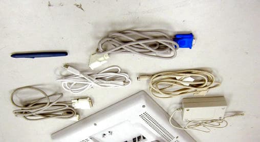
Click to zoom
Application Details
- Equipment Class
- DCD - Part 15 Low Power Transmitter Below 1705 kHz
- Date of Grant
- Oct 17, 2002
- Application Purpose
- Original Equipment
- Date of Application
- Oct 17, 2002
- Equipment Note
- 17" LCD Pen Tablet System
- Frequency Range
- 0.53125000 - 0.59375000
- Company
- Wacom Co Ltd
- Country
- Japan
Documents & Files
Document Text
Text extracted from the exhibit documents filed with the FCC. Open a document above to read the original.
Users Manual
The equipment described in this manual generates, uses, and can radiate radio-frequency energy. If it is not installed and used properly that is, in strict accordance with Wacom instructions it may cause inter- ference with radio and television reception. Federal Communications Commission (FCC) Notice This equipment has been tested and found to comply with the limits for Class B digital devices, pursuant to Part 15 of FCC Rules. These limits are designed to provide reasonable protection against harmful interfer- ence in a residential installation. This equipment generates, uses and can radiate radio frequency energy and, if not installed and used in accordance with the instructions, may cause harmful interference to radio communications. However, there is no guarantee that interference will not occur in a particular installation. You can determine whether the tablet equipment is causing interference by powering it off. If the interfer- ence stops, it was probably caused by the tablet. If your tablet equipment does cause interference to radio or television reception, you may be able to correct the interference by using one or more of the following measures: - Rotate the television or radio antenna until the interference stops. - Move the tablet equipment farther away from the television or radio. - Plug the tablet equipment and computer into an outlet that is on a different circuit from the television or radio. If necessary, consult your Wacom dealer or an experienced radio/television technician for help. Changes or modifications to this product not authorized by Wacom could void the FCC Certification and negate your authority to operate the product. Radio and Television Interference (U.S.A.) 02.7.16, 5:10 PM1 2 Table of Centents Checking Packed Components3 Installation4 LCD Monitor Installation Wacom Tablet Software Installation Calibrating the Tablet PL-700 Component Functions8 Front View Rear View Mounting the PL-700 onto a Mount Arm or Other Stand Caring For Your PL-700 Using the UltraPen UltraPen Pen Type Settings in the Wacom Tablet Control Panel Replacing the Pen Tip Specifications13 General Specifications LCD Display Tablet UltraPen 02.7.16, 5:10 PM2 3 Checking Packed Components In your package you will find the following items: USB Cble or RS-232C Cable DVI-DVI Cable or DVI-RGB Cable PL-700 UltraPen with Pen Stand User s Manual Wacom Software CD Contains the Interactive Pen Display software and a Readme file (Windows/Macintosh) AC Adaptor and Power Cable 02.7.16, 5:10 PM3 4 Installation LCD Monitor Installation First install the PL-700 as a monitor. Do not connect the USB cable or serial data cable until instructed in the tablet software installation. Turn off your computer. Caution: Never connect or disconnect the DVI video cable or power cable while your computer or the PL-700 is powered on. This can damage the LCD display or video card. Connect the DVI-DVI cable or DVI-RGB between the PL-700 and your computer. Set the DVI / Analog RGB switch. Turning up is for Analog RGB, and turning down is for DVI. Connect the AC adaptor to the PL-700. Connect the AC adaptor power cable and plug the adaptor into an AC outlet. CAUTION 02.7.16, 5:10 PM4 5 Wacom Tablet Software Installation After setting the monitor for proper size and color resolution, turn off your computer and connect the USB cable or serial data cable. ( ) Then, install the Wacom tablet software. Refere to the Tablet Software Installation Guide for the instructions. Calibrating the Tablet As necessary, you can calibrate the tablet in order to line up the screen cursor position with the position of the UltraPen on the Interactive Pen Display. This is required to adjust for parallax caused by the glass overlay. To calibrate the tablet, from the Wacom Tablet Control Panel, select the Monitor tab. Refere to the Wacom Tablet Help for details. Turn on the power switch of the PL-700. The power lamp will lite green, and then turns orange. Turn on your computer to start your operating system. As necessary configure the monitor settings for proper size and color resolution. (The recommended resolution is 1280 x 1024. Other settings may give unsatisfactory results.) the color palett and number of locors are as follows: - High Color (16 bit), 65,536 color - True Color (24 bit), 16,770,000 color approximate The number of colotrs is constrained by the performance of your computer or graphics card. Refere to the documentation of the manufacturer for datails. 02.7.16, 5:10 PM5 6 Front View - On a TFT liquid crystal display, a very small number of pixels may be permanently illuminated or not illuminated at all. This does not mean that the display is defective. - When pressing the LCD panel hard it may temporaryly cause moire to appear. This does not mean the display is defective. - When a still image is displayed for a long period of time, a n after image may temporaryly remain. Power Switch Turns the power to the PL-700 on or off. Power Lamp Lights green when power has properly been supplied to the PL-700. Turns orange or flashes when your computer goes into power management mode and stops sending the video signal to the PL-700. Status Lamp Lights green when a pen switch is pressed. ENTER Button Press this button when you select or exit an item in the OSD menu. + (plus) Button, - (minus)Button Press this button when you change the option or settings in the OSD menu. MENU Button Opens or closes the OSD menu. POWER STATUS ENTER EN - MENU *1 + - PL-700 Component Functions 02.7.16, 5:10 PM6 7 The stand can be used to adjust the tilt angle of the unit from low (18° from horizontal) to high (72° from horizontal). Rear View Pulling this lever allows the stand to move freely. Releasing the lever locks the stand in place. CAUTION IMPOTANT Be sure to close the stand when packing the Cintiq Interactive Pen Display. If you do not close the stand, the notched mechanism may be damaged during transportation and storage. Do not lift the PL-700 by the stan…
Text truncated - open the document above for the full version.
External Photos
ETC Report No.: ET91S-09-134Page A1 of A3 FCC ID: HV4PL700 ANNEX A: EXTERNAL CONSTRUCTION PHOTOS OF EUT 1. Front view 1 of EUT 2. Rear view 1 of EUT ETC Report No.: ET91S-09-134Page A2 of A3 FCC ID: HV4PL700 3. Front view 2 of EUT 4. Rear view 2 of EUT ETC Report No.: ET91S-09-134Page A3 of A3 FCC ID: HV4PL700 5. Front view 3 of EUT 6. Rear view 3 of EUT
Internal Photos
ETC Report No.: ET91S-09-134Page B1 of B15 FCC ID: HV4PL700 ANNEX B: INTERNAL CONSTRUCTION PHOTOS OF EUT 1. Inside 1 of EUT (Monitor) 2. Inside 2 of EUT (Monitor) ETC Report No.: ET91S-09-134Page B2 of B15 FCC ID: HV4PL700 3. Inside 3 of EUT (Monitor) 4. Inside 4 of EUT (Monitor) ETC Report No.: ET91S-09-134Page B3 of B15 FCC ID: HV4PL700 5. Inside 5 of EUT (Monitor) 6. Inside 6 of EUT (Monitor) ETC Report No.: ET91S-09-134Page B4 of B15 FCC ID: HV4PL700 7. Inside 7 of EUT (Adaptor) 8. Inside 8 of EUT (Adaptor) ETC Report No.: ET91S-09-134Page B5 of B15 FCC ID: HV4PL700 9. Inside 9 of EUT (Adaptor) 10. Inside 10 of EUT (Adaptor) ETC Report No.: ET91S-09-134Page B6 of B15 FCC ID: HV4PL700 11. Inside 11 of EUT (Adaptor) 12. Modify (Monitor) ETC Report No.: ET91S-09-134Page B7 of B15 FCC ID: HV4PL700 13. Front view of PCB 1 (Monitor) 14. Rear view of PCB 1 (Monitor) ETC Report No.: ET91S-09-134Page B8 of B15 FCC ID: HV4PL700 15. Front view of PCB 2 (Monitor) 16. Rear view of PCB 2 (Monitor) ETC Report No.: ET91S-09-134Page B9 of B15 FCC ID: HV4PL700 17. Front view of PCB 3 (Monitor) 18. Rear view of PCB 3 (Monitor) ETC Report No.: ET91S-09-134Page B10 of B15 FCC ID: HV4PL700 19. Front view of PCB 4 (Monitor) 20. Rear view of PCB 4 (Monitor) ETC Report No.: ET91S-09-134Page B11 of B15 FCC ID: HV4PL700 21. Front view of PCB 5 (Monitor) 22. Rear view of PCB 5 (Monitor) ETC Report No.: ET91S-09-134Page B12 of B15 FCC ID: HV4PL700 23. Front view of PCB 5 (Monitor) – Take off the shielding 24. Rear view of PCB 5 (Monitor) - Take off the shielding ETC Report No.: ET91S-09-134Page B13 of B15 FCC ID: HV4PL700 25. Front view of PCB 6 (Monitor) 26. Rear view of PCB 6 (Monitor) ETC Report No.: ET91S-09-134Page B14 of B15 FCC ID: HV4PL700 27. Front view of PCB 7 (Monitor) 28. Rear view of PCB 7 (Monitor) ETC Report No.: ET91S-09-134Page B15 of B15 FCC ID: HV4PL700 29. Front view of PCB 8 (Adaptor) 30. Rear view of PCB 8 (Adaptor)
Test Report
FCC ID: HV4PL700 Rev. No 1.0 FCC Part 15 Subpart C EMI TEST REPORT of E.U.T. : 17” LCD Pen Tablet System FCC ID. : HV4PL700 MODEL: PL-700 Working Frequency: 531.25 kHz(CH1), 562.50 kHz(CH2), 593.75 kHz(CH3) Issused Dated: Oct. 01, 2002 for APPLICANT: NESO TECHNOLOGY INC. ADDRESS: 4F, No. 102, Chung Shan Rd. Sec. 3, Chung Ho City, Taipei Hsien, Taiwan, R.O.C. Test Performed by ELECTRONICS TESTING CENTER, TAIWAN NO. 8 LANE 29, WENMIMG ROAD, LOSHAN TSUN, KWEISHAN HSIANG, TAOYUAN, TAIWAN, R.O.C. Tel:(03)3276170-3276174 Fax:(03)3276188 Report Number : ET91S-09-134 ETC Report No: ET91S-09-134FCC ID: HV4PL700 Rev. No 1.0 TEST REPORT CERTIFICATION Applicant: NESO TECHNOLOGY INC. 4F, No. 102, Chung Shan Rd. Sec. 3, Chung Ho City, Taipei Hsien, Taiwan, R.O.C. Manufacturer: Foxlink Image Technology., LTD. No. 18, Chung-Shan Road, Tu-Cheng City, Taipei Hsien, Taiwan, R.O.C. Description of EUT: a) Type of EUT: 17” LCD Pen Tablet System b) Trade Name: WACOM c) Model No.: PL-700 d) FCC ID: HV4PL700 e) Working Frequency: 531.25 kHz(CH1), 562.50 kHz(CH2), 593.75 kHz(CH3) f) Power Supply: Adaptor: I/P: AC100~240V, 50/60Hz, 1.5A O/P: 18V, 3.33A M/N: LE-9702B-01A Regulation Applied: FCC Rules and Regulations Part 15 Subpart C (2001) I HEREBY CERTIFY THAT; The data shown in this report were made in accordance with the procedures given in ANSI C63.4 and the energy emitted by the device was founded to be within the limits applicable. I assume full responsibility for accuracy and completeness of these data. Note: 1. The results of the testing report relate only to the items tested. 2. The testing report shall not be reproduced except in full, without the written approval of ETC. Test Date : Sep. 25, 2002 Test Engineer : Approve & Authorized Signer : Win-Po Tsai, Manager, NVLAP Signatory EMC Dept. I of ELECTRONICS TESTING CENTER, TAIWAN ETC Report No: ET91S-09-134FCC ID: HV4PL700 Rev. No 1.0 Table of Contents Page 1. GENERAL INFORMATION.............................................................................................................................................................1 1.1 PRODUCT DESCRIPTION..................................................................................................................................................................1 1.2 CHARACTERISTICS OF DEVICE:.......................................................................................................................................................1 1.3 TEST METHODOLOGY......................................................................................................................................................................1 1.4 TEST FACILITY..................................................................................................................................................................................1 2. DEFINITION AND LIMITS..............................................................................................................................................................2 2.1 DEFINITION........................................................................................................................................................................................2 2.2 RESTRICTED BANDS OF OPERATION.............................................................................................................................................2 2.3 LIMITATION.......................................................................................................................................................................................2 2.4 LABELING REQUIREMENT...............................................................................................................................................................4 2.5 USER INFORMATION.........................................................................................................................................................................4 3. RADIATED EMISSION MEASUREMENT....................................................................................................................................5 3.1 APPLICABLE STANDARD................................................................................................................................................................5 3.2 DEVICES FOR TESTED SYSTEM.......................................................................................................................................................5 3.3 MEASUREMENT PROCEDURE..........................................................................................................................................................5 3.4 TEST DATA........................................................................................................................................................................................8 3.5 FIELD STRENGTH CALCULATION................................................................................................................................................10 3.6 RADIATED TEST EQUIPMENT......................................................................................................................................................10 3.7 MEASURING INSTRUMENT SETUP...............................................................................................................................................11 3.8 RADIATED MEASUREMENT PHOTOS...........................................................................................................................................12 4. CONDUCTED EMISSION MEASUREMENT.............................................................................................................................13 4.1 APPLICABLE STANDARD..............................................................................................................................................................13 4.2 MEASUREMENT PROCEDURE.................…
Text truncated - open the document above for the full version.
Test Setup Photos
ETC Report No.: ET91S-09-134Page 1 of 2 FCC ID: HV4PL700 Rev. No 1.0 3.8 Radiated Measurement Photos ETC Report No.: ET91S-09-134Page 2 of 2 FCC ID: HV4PL700 Rev. No 1.0 4.6 Photos of Conduction Measuring Setup
Contact Information
Applicant
Koichi Yokoyama(Senior Director, Quality Assurance)
Test Firm
Electronics Testing Center, TaiwanWin-Po Tsai
Technical Specifications
| # | Rule Parts | Frequency Range | Power Output |
|---|---|---|---|
| 1 | 15C | 0.53125 MHz - 0.59375 MHz | - |
Other Applications from Wacom Co Ltd
HV4CTK6120
Aug 19, 2026Pen Tablet
Equipment Class
DCD - Part 15 Low Power Transmitter Below 1705 kHzHV4STU540A
May 12, 2026LCD SIGNATURE PAD
Equipment Class
DCD - Part 15 Low Power Transmitter Below 1705 kHzHV4DTHA140
Sep 16, 2025Portable Pad
Equipment Class
DTS - Digital Transmission SystemHV4PTK470
Oct 10, 2024Creative Pen Tablet
Equipment Class
DTS - Digital Transmission SystemHV4PTK870
Oct 10, 2024Creative Pen Tablet
Equipment Class
DCD - Part 15 Low Power Transmitter Below 1705 kHz