HV4STU500BLCD Signature Tablet
Wacom Co Ltd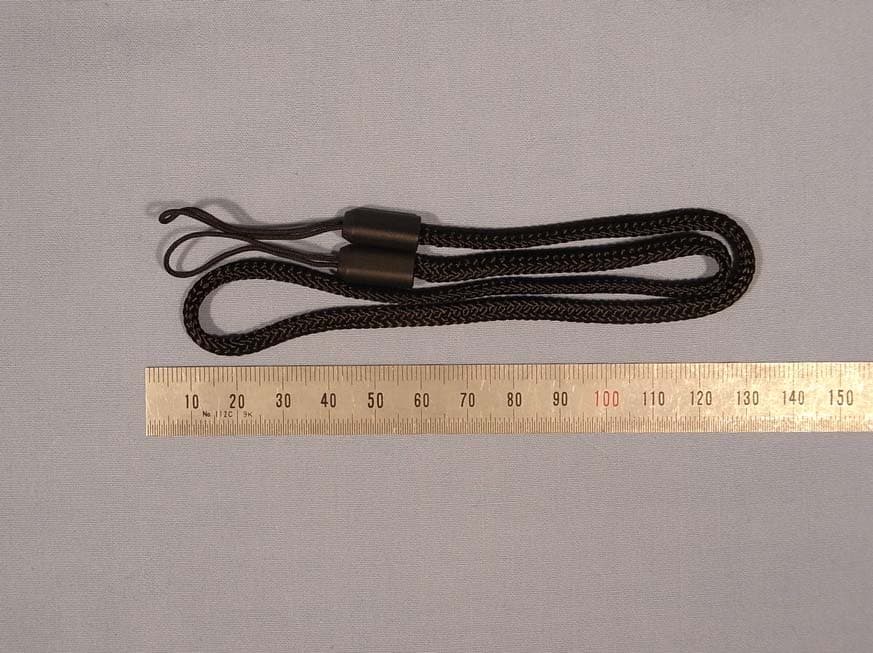
Click to zoom
Application Details
- Equipment Class
- DCD - Part 15 Low Power Transmitter Below 1705 kHz
- Date of Grant
- Sep 13, 2010
- Application Purpose
- Original Equipment
- Date of Application
- Sep 13, 2010
- Equipment Note
- LCD Signature Tablet
- Frequency Range
- 0.56300000 - 0.56300000
- Company
- Wacom Co Ltd
- Country
- Japan
Documents & Files
Document Text
Text extracted from the exhibit documents filed with the FCC. Open a document above to read the original.
Users Manual
Instruction Manual LCD Signature Tablet STU-500B Ver. 1.1 8 Sep, 2010 WACOM Co., Ltd WACOM Co., Ltd. 1 Table of contents 1. SCOPE ...........................................................................................................................................................2 2. SUMMARY .....................................................................................................................................................2 3. PRECAUTIONS ON USE AND HANDLING .................................................................................................2 4. CAUTIONS FOR USING STU-500B ..............................................................................................................5 5. PRODUCT SPECIFICATION ...........................................................................................................................6 5-1 GENERAL SPECIFICATIONS ........................................................................................................................................... 6 5-2 COMPLIANCE ................................................................................................................................................................ 6 5-3 COORDINATE ................................................................................................................................................................ 7 5-4 INTERFACE SPECIFICATIONS ........................................................................................................................................ 7 5-5 STATUS LED ............................................................................................................................................................... 7 5-6 LCD ............................................................................................................................................................................ 7 5-7 ENVIRONMENTAL CONDITIONS ..................................................................................................................................... 8 6. ACCESSORIES AND OPTIONAL SERIAL KIT ........................................................................................8 6-1 ACCESSORY LIST (STU-500B) .................................................................................................................................... 8 6-2 OPTIONAL SERIAL KIT (FUZ-A147-01/-02/-03) ........................................................................................................... 8 6-3 PEN SPECIFICATION ..................................................................................................................................................... 9 6-3 USB CABLE(STJ-A257) ............................................................................................................................................ 10 7. FIXING STU-500B ......................................................................................................................................... 11 8. REPLACING THE PEN TIP ......................................................................................................................... 14 9. HOW TO INSTALL PEN TETHER .............................................................................................................. 15 WACOM Co., Ltd. 2 1. Scope This instruction manual applies to the LCD Signature tablet STU-500B. 2. Summary The Wacom® STU-500B LCD signature tablet combines the benefi ts of a liquid crystaldisplay (LCD) with the control, comfort, and productivity of Wacom’s cordless, batteryfree pen technology. This gives you a direct pen-on-screen interface that leads to a truer pen-on-paper writing experience. The basic components of the LCD signature tablet include a Wacom pen tablet internally mounted behind a 5" diagonal TFT monochrome LCD display, and a Wacom pen. The LCD signature tablet is equipped with a USB and RS-232C interfaces. 3. Precautions on use and handling Be sure to follow all instructions, cautions, and warnings found within this guide. Failure to do so could cause the loss of data or damage to your computer. Failure to do so could also void your warranty, in which case Wacom shall have no responsibility to repair or replace the product. Usage WARNING Do not use the STU-500B LCD signature tablet in a facility control system that requires extremely high reliability; it may cause other electronic devices to malfunction, or other devices may cause the LCD signature tab let to malfunction. Where use is prohibited, power off the STU-500B to prevent the possibility of it causing other electronic devices to malfunction. Wacom does not accept any liability for direct or consequential damages. For details, please refer to your Warranty located at the end of this guide. Environment Temperature and humidity Operating temperature and humidity: 5° to 35°C, 20 to 80% RH Storage temperature and humidity: -10° to 60°C, 20 to 90% RH CAUTION Do not use or store the LCD signature tablet where: Temperature changes are severe or exceed specifications (e.g., outdoors or inside a vehicle). The LCD signature tablet and pen are exposed to direct sunlight or heat from an appliance, or are exposed to water or any other kind of liquid. Do not use the LCD signature tablet in a dusty environment; this may damage the unit. WACOM Co., Ltd. 3 Handling WARNING If using a power adapter with the STU-500B, only use the power adapter (Serial kit FUZ-A147) that designed for use with the STU-500B. If a different type of power adapter is used, the LCD signature tablet will not work properly or may be damaged. Using a different type of power adapter also has the potential to result in fi re. Use of a different power adapter will void your warranty. When not using the LCD signature tablet for long periods of time, unplug the power adapter from the AC outlet. WARNING High Voltage. Do not open or disassemble the STU-500B LCD signature tablet. T…
Text truncated - open the document above for the full version.
External Photos
Wacom Co., Ltd. FCC ID: HV4STU500B IC: 6888A-STU500B Page 1 of 6 Wacom Co., Ltd. FCC ID: HV4STU500B IC: 6888A-STU500B Page 2 of 6 Wacom Co., Ltd. FCC ID: HV4STU500B IC: 6888A-STU500B Page 3 of 6 Wacom Co., Ltd. FCC ID: HV4STU500B IC: 6888A-STU500B Page 4 of 6 Wacom Co., Ltd. FCC ID: HV4STU500B IC: 6888A-STU500B Page 5 of 6 Wacom Co., Ltd. FCC ID: HV4STU500B IC: 6888A-STU500B Page 6 of 6
ID Label/Location Info
Location of label
Internal Photos
Wacom Co., Ltd. FCC ID: HV4STU500B IC: 6888A-STU500B Page 1 of 12 Wacom Co., Ltd. FCC ID: HV4STU500B IC: 6888A-STU500B Page 2 of 12 Wacom Co., Ltd. FCC ID: HV4STU500B IC: 6888A-STU500B Page 3 of 12 Wacom Co., Ltd. FCC ID: HV4STU500B IC: 6888A-STU500B Page 4 of 12 Wacom Co., Ltd. FCC ID: HV4STU500B IC: 6888A-STU500B Page 5 of 12 Wacom Co., Ltd. FCC ID: HV4STU500B IC: 6888A-STU500B Page 6 of 12 Wacom Co., Ltd. FCC ID: HV4STU500B IC: 6888A-STU500B Page 7 of 12 Wacom Co., Ltd. FCC ID: HV4STU500B IC: 6888A-STU500B Page 8 of 12 Wacom Co., Ltd. FCC ID: HV4STU500B IC: 6888A-STU500B Page 9 of 12 Wacom Co., Ltd. FCC ID: HV4STU500B IC: 6888A-STU500B Page 10 of 12 Wacom Co., Ltd. FCC ID: HV4STU500B IC: 6888A-STU500B Page 11 of 12 Wacom Co., Ltd. FCC ID: HV4STU500B IC: 6888A-STU500B Page 12 of 12
Test Report
Report number: Z071C-10157 Page 2 of 18 ZACTA Technology Corp. FCC ID: HV4STU500B FCC 15C Rev.3.0 IC Certification Number: 6888A-STU500B Table of contents Page 1. Summary of Test.................................................................................................................................................................. 4 1.1 Purpose of test..........................................................................................................................................................................4 1.2 Standards ..................................................................................................................................................................................4 1.3 Summary of test results ...........................................................................................................................................................4 1.4 Deviation from the standard....................................................................................................................................................4 1.5 Modification to the EUT by laboratory ..................................................................................................................................4 2. Equipment description......................................................................................................................................................... 5 2.1 General Description of equipment..........................................................................................................................................5 2.2 EUT information......................................................................................................................................................................5 2.3 Operating mode .......................................................................................................................................................................5 3. Configuration information................................................................................................................................................... 6 3.1 EUT and Peripheral(s) used ....................................................................................................................................................6 3.2 Cable(s) information................................................................................................................................................................6 3.3 System configuration...............................................................................................................................................................7 4. Test Type and Results .......................................................................................................................................................... 8 4.1 99% Occupied Bandwidth ......................................................................................................................................................8 4.1.1 Test Procedure [ IC RSS-210 A8.1(a) ]..........................................................................................................................8 4.1.2 Measurement Setup ...........................................................................................................................................................8 4.1.3 Limit of Bandwidth at 99% Occupied Bandwidth ...........................................................................................................8 4.1.4 Measurement Result ..........................................................................................................................................................9 4.1.5 Trace Data..........................................................................................................................................................................9 4.2 Radiated Emissions (9kHz – 1000MHz)............................................................................................................................. 10 4.2.1 Test Procedure [ FCC 15.209, IC RSS-210 2.2, RSS-Gen 4.9, 4.10, 4.11 ]................................................................10 4.2.2 Measurement Setup .........................................................................................................................................................10 4.2.3 Limit of Spurious Emission Measurement .....................................................................................................................11 4.2.4 Calculation Method .........................................................................................................................................................11 4.2.5 Measurement Results ......................................................................................................................................................11 4.3 AC power line Conducted Emissions .................................................................................................................................. 13 4.3.1 Test Procedure [ FCC 15.207, IC RSS-Gen 7.2.2 ] .....................................................................................................13 4.3.2 Measurement Setup .........................................................................................................................................................13 4.3.3 Limit of AC power line Conducted Emissions Measurement ........................................................................................14 4.3.4 Calculation method..........................................................................................................................................................14 4.3.5 Measurement Result .....................................................................................................................................................…
Text truncated - open the document above for the full version.
Test Setup Photos
Wacom Co., Ltd. FCC ID: HV4STU500B IC: 6888A-STU500B Radiated Emission The photographs show maximized emission configuration. Wacom Co., Ltd. FCC ID: HV4STU500B IC: 6888A-STU500B Conducted Emission at mains port The photographs show maximized emission configuration.
Contact Information
Applicant
Koichi Yokoyama(Senior Director, Quality Assurance)
Test Firm
TUV SUD Japan Ltd. Yonezawa Testing CenterHiroaki Suzuki
[email protected]81-238-40-1681
Technical Specifications
| # | Rule Parts | Frequency Range | Power Output |
|---|---|---|---|
| 1 | 15C | 0.563 MHz - 0.563 MHz | - |
Other Applications from Wacom Co Ltd
HV4CTK6120
Aug 19, 2026Pen Tablet
Equipment Class
DCD - Part 15 Low Power Transmitter Below 1705 kHzHV4STU540A
May 12, 2026LCD SIGNATURE PAD
Equipment Class
DCD - Part 15 Low Power Transmitter Below 1705 kHzHV4DTHA140
Sep 16, 2025Portable Pad
Equipment Class
DTS - Digital Transmission SystemHV4PTK470
Oct 10, 2024Creative Pen Tablet
Equipment Class
DTS - Digital Transmission SystemHV4PTK870
Oct 10, 2024Creative Pen Tablet
Equipment Class
DCD - Part 15 Low Power Transmitter Below 1705 kHz