HYQ13BBHRemote Keyless Entry System, Model 13BBH
Denso Corporation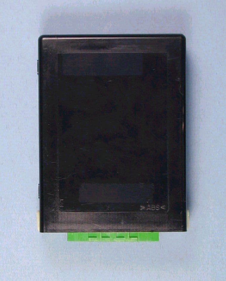
Click to zoom
Application Details
- Equipment Class
- CYY - Communications Receiver used w/Pt 15 Transmitter
- Date of Grant
- Dec 21, 2000
- Application Purpose
- Original Equipment
- Date of Application
- Nov 14, 2000
- Equipment Note
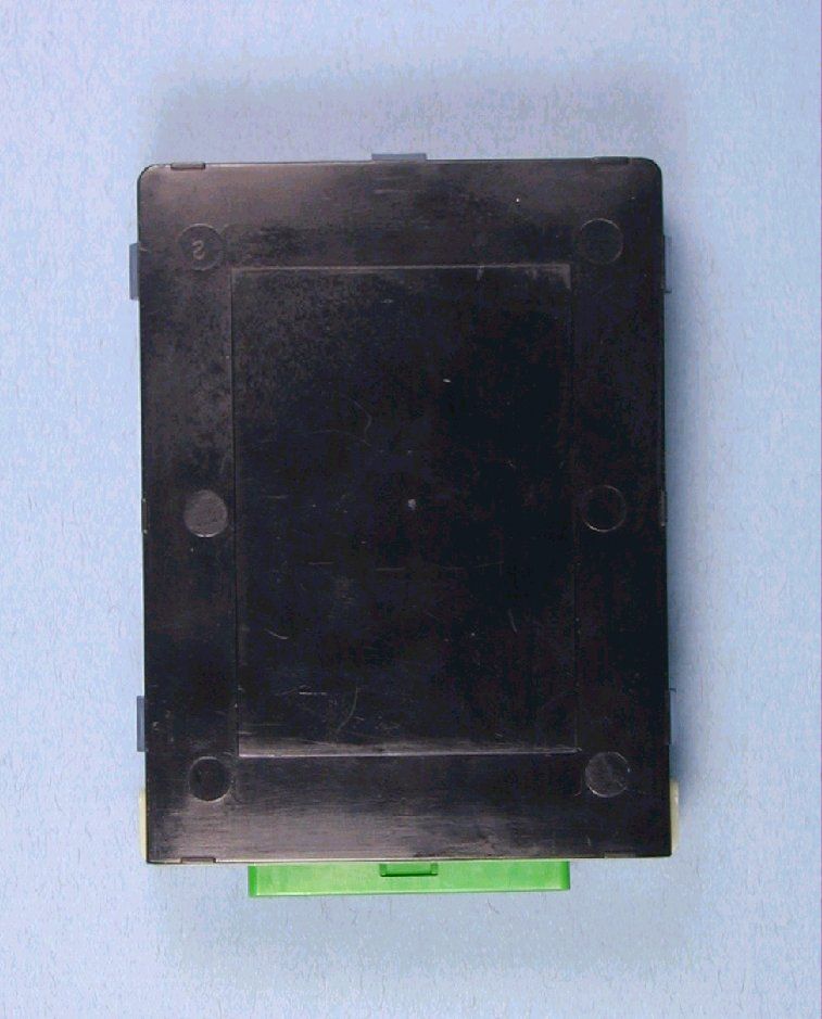
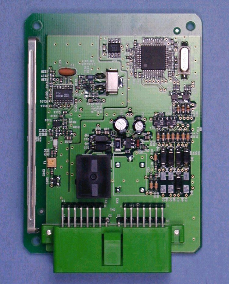
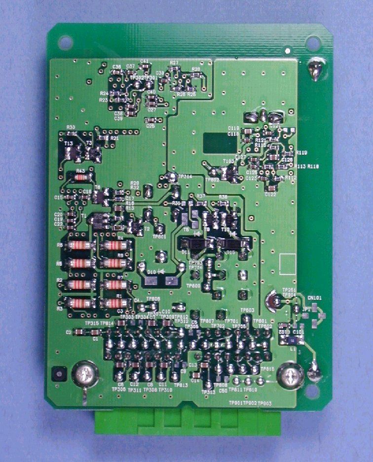
- Remote Keyless Entry System, Model 13BBH
- Frequency Range
- 314.35000000 - 314.35000000
- Company
- Denso Corporation
- Country
- Japan
Documents & Files
Document Text
Text extracted from the exhibit documents filed with the FCC. Open a document above to read the original.
Users Manual
1-1,Showa-cho, Kariya-shi, Aichi-ken, 448-8661, Japan Engineering Administration Department Tel : +81-566-25-5922 Fax : +81-566-25-4548 Federal Communications Commission 1919 M Street N.W. Washington DC 20554 Subject: Instruction Manual/Compliance Statement for FCC IDs HYQ13BBH, Remote Keyless Entry System , Receiver for cars. Dear Sirs, Our product 13BBH is a receiver for Remote Keyless Entry System for cars. It will be already installed in cars (as original equipment) when it will be placed into the US market. We, DENSO CORPORATION, do not issue any users manual for this product. Yours Sincerely, Kazuo Sakakibara Manager Engineering Administration Department DENSO CORPORATION
Attestation Statements
TÜV MANAGEMENT SERVICEPhone: (651) 631 2487 TÜV PRODUCT SERVICE INC.Fax: (651) 638 0285 1775 Old Highway 8 NW, Suite 104email [email protected] New Brighton MN 55112-1891http:://www.tuvglobal.com Divisions of TÜV America Inc., a subsidiary of TÜV Süddeutschland and TÜV Nord Group TÜV PRODUCT SERVICE INC 19333 WILD MOUNTAIN ROAD TAYLORS FALLS, MINNESOTA 55084-1786 ENGINEERING STATEMENT For Certification of DENSO Corporation Super-heterodyne Receiver for Remote Keyless Entry System for Vehicles Model No: 13BBH I am an Electromagnetic Compatibility Engineer for TÜV PRODUCT SERVICE INC, Taylors Falls, Minnesota. My education and experience are a matter of record with the Federal Communications Commission. TÜV PRODUCT SERVICE INC has been authorized Senichi Nagata, General Manager, of DENSO Corporation, to make Certification measurements on the Receiver for a Tire Pressure Monitor system. These tests were made by me or under my supervision at our Wild River Laboratory which is on file with the FCC under Paragraph 2.948 of the FCC Rules. Test data required by the FCC is included in this report. It is submitted that the above equipment meets the FCC Part 15 Requirements and Certification is hereby requested. Joel T Schneider Minnesota Lead Engineer Minnesota Wild River Lab TÜV Product Service [email protected] Dated: 06 September 2000
Block Diagram
4 4. Block diagram 4.1. Receiver Fig. Block diagram of receiver 60.73MHz 303.65 MHz DETECTOR To CPU COMPARATER LOW PASS FILTER IF AMP RSSI RF FILTER X5 OSC RF AMP MIXER IF FILTER
ID Label/Location Info
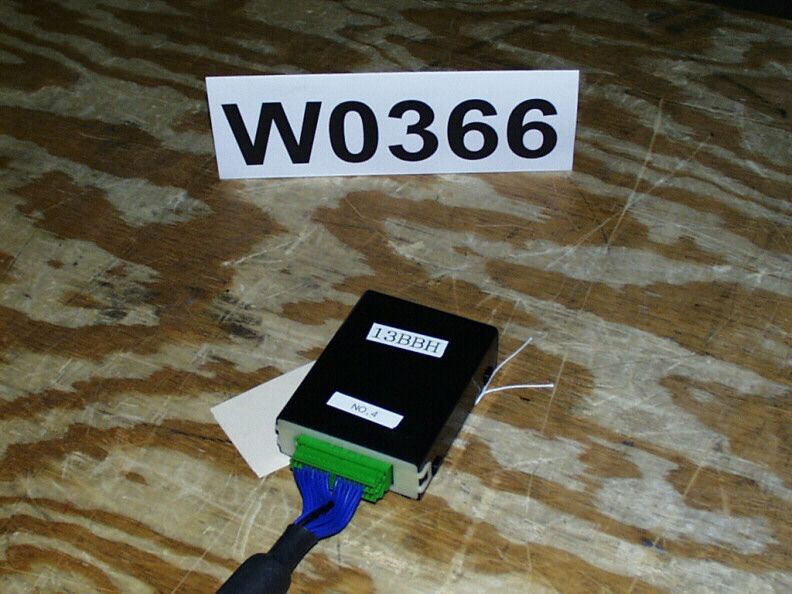
8 7. Marking location and layout 7.1. Receiver Fig. Marking location and layout of receiver Note: Compliance statement of marking will not be changed. But marking layout and size maybe changed.
Operational Description
2 2. Technical description of the system 2.1. Type number - Receiver: 13BBH 2.2. Specifications of receiver - Nominal frequency: 314.35 MHz - Local Oscillator Frequency : 303.65 MHz - Micro computer clock frequency: 3.86 MHz - Type of receiving system: Super-heterodyne - Power Supply - Nominal supply voltage: 12 VDC (vehicle battery) - Antenna: Built-in type (Fixed) 3 3. Outline of the system 3.1. Description of the system operation This system is mainly used for locking or unlocking the doors of the vehicle. The transmitter send a radio wave signal while the button is pushed. The receiver becomes active in response to the signal from the transmitter. 3.2. Installation in vehicle The receiver is installed inside the vehicle.
Parts List/Tune Up Info
6 6. Component listing 6.1. Receiver (1/2) Part NameDescriptionNumber of Units IC-1 Transistor-2 Diode-1 Inductor10 - 82nH or nothing1 Inductor10 - 47nH1 Inductor10 - 56nH1 Inductor15 - 39nH1 Inductor 0.22 - 0.56μH 1 Capacitor330 - 1000pF2 Capacitor0.5 -1000pF1 Capacitor0.5 - 1000pF or nothing2 Capacitor1 - 10pF2 Capacitor1 - 10pF or nothing1 Capacitor1 - 47pF1 Capacitor5 - 15pF1 Capacitor5 - 47pF1 Capacitor10 - 47pF1 Capacitor 220p - 0.01μF 1 Capacitor390 - 1000pF1 Capacitor1000pF3 Capacitor 1000pF - 0.1μF 1 Capacitor 0.01μF 7 Capacitor 0.22μF 1 Capacitor 0.1μF 3 Capacitor 0.1μF or nothing 1 7 6.1. Receiver (2/2) Part NameDescriptionNumber of Units Resistor 100Ω 2 Resistor 470Ω 1 Resistor 1kΩ 2 Resistor 680Ω-3kΩ 1 Resistor 5-10kΩ 1 Resistor 10kΩ 5 Resistor 10-25kΩ 1 Resistor 12kΩ 2 Resistor 16kΩ 1 Resistor 18kΩ 1 Resistor 22kΩ 2 Resistor 100kΩ 1 Filter314.35MHz1 Filter10.7MHz1 Crystal60.73MHz1 Antenna-1 Jumper-1
Schematics
5 5. Circuit diagram 5.1 Receiver Fig. Circuit diagram of receiver
Test Report
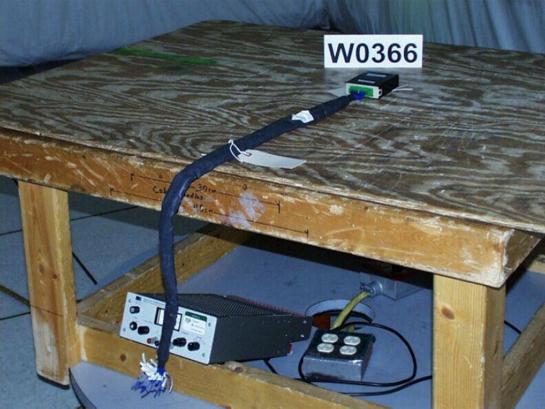
PRODUCT SERVICE TEST RESULT SUMMARY FCC PART 15 SUBPART B Class B Limit MANUFACTURER'S NAMEDenso Corporation NAME OF EQUIPMENTSuperheterodyne Receiver for remote keyless entry system in vehicle MODEL NUMBER 13BBH APPLICANT'S ADDRESS1-1 Showa-cho, Kariya-shi Aichi-ken, 448-8661 Japan TEST REPORT NUMBERW0366 TEST DATE07 July 2000 According to testing performed at TÜV Product Service Inc, the above-mentioned unit is in compliance with the electromagnetic compatibility requirements defined in FCC Part 15. It is the manufacturer's responsibility to assure that additional production units of this model are manufactured with identical electrical and mechanical characteristics. Any modifications necessary for compliance made during testing on the above mentioned date(s) must be implemented in all production units for compliance to be maintained. TÜV Product Service Inc, as an independent testing laboratory, declares that the equipment tested as specified above conforms to the requirements of FCC Part 15. Date:15 August 2000 Location:Taylors Falls MNG. S. JakubowskiJ. T. Schneider USATest EngineerNVLAP Signatory Not Transferable File No. WC1H036601, Page 1 of 12 TÜV PRODUCT SERVICE INC19333 Wild Mountain RoadTaylors Falls MN 55084-1758Tel: 651 638 0297Fax: 651 638 0298Rev.No 1.0 PRODUCT SERVICE EMC EMISSION - T E S T R E P O R T Test Report File No.: WC1H036601 Date of issue:15 August 2000 Model / Serial No.: 13BBH / Product Type: Superheterodyne Receiver for remote keyless entry system in vehicle Applicant: Denso Corporation Manufacturer: Denso Corporation License holder: Denso Corporation Address: 1-1 Showa-cho, Kariya-shi : Aichi-ken, 448-8661 Japan Test Result: nn Positiveoo Negative Test Project Number: Reference(s) W0366 Total pages including Appendices21 TÜV Product Service Inc is a subcontractor to TÜV Product Service, GmbH according to the principles outlined in ISO/IEC Guide 25 and EN 45001. TÜV Product Service Inc reports apply only to the specific samples tested under stated test conditions. It is the manufacturer's responsibility to assure that additional production units of this model are manufactured with identical electrical and mechanical components. TÜV Product Service Inc shall have no liability for any deductions, inferences or generalizations drawn by the client or others from TÜV Product Service Inc issued reports. This report is the confidential property of the client. As a mutual protection to our clients, the public and ourselves, extracts from the test report shall not be reproduced except in full without our written approval. This report shall not be used by the client to claim product endorsement by NVLAP or any agency of the US government. TÜV Product Service Inc and its professional staff hold government and professional organization certifications and are members of AAMI, ACIL, AEA, ANSI, IEEE, NVLAP, and VCCI File No. WC1H036601, Page 2 of 12 TÜV PRODUCT SERVICE INC19333 Wild Mountain RoadTaylors Falls MN 55084-1758Tel: 651 638 0297Fax: 651 638 0298Rev.No 1.0 PRODUCT SERVICE D I R E C T O R Y - EMISSIONS Page(s) A)Documentation Test report1 – 10 Directory2 Test Regulations3 Deviations from standard / Summary10 Test-setups (Photos)11 – 12 Test-setup (drawing)Appendix A B)Test data Conducted emissions10/150 kHz - 30 MHz5, 9 Radiated emissions10 kHz - 30 MHz5, 9 Radiated emissions30 MHz - 1000 MHz6, 9 Interference power30 MHz - 300 MHz6, 9 Equivalent Radiated emissions1 GHz - 18 GHz7, 9 C)Appendix A Test Data Sheets and Test Setup Drawing(s) A2 – A4 D)Appendix B Constructional Data Form B2 Product Information Form(s) B3 E)Appendix C Measurement ProtocolC1 - C2 File No. WC1H036601, Page 3 of 12 TÜV PRODUCT SERVICE INC19333 Wild Mountain RoadTaylors Falls MN 55084-1758Tel: 651 638 0297Fax: 651 638 0298Rev.No 1.0 PRODUCT SERVICE EMISSIONS TEST REGULATIONS : The emissions tests were performed according to following regulations: -------------------------------------------------------------------------------- o - EN 50081-1 / 1991 o - EN 55011 / 1991o - Group 1o - Group 2 o - Class Ao - Class B o - EN 55013 / 1990 o - EN 55014 / 1987o - Household appliances and similar o - Portable tools o - Semiconductor devices o - EN 55014 / A2:1990 o - EN 55014 / 1993o - Household appliances and similar o - Portable tools o - Semiconductor devices o - EN 55015 / 1987 o - EN 55015 / A1:1990 o - EN 55015 / 1993 o - EN 55022 / 1987o - Class Ao - Class B o - EN 55022 / 1994o - Class Ao - Class B o - BS o - VCCIo - Class Ao - Class B n - FCCo - Class An - Class B o - AS 3548 (1992)o - Class Ao - Class B o - CISPR 11 (1990) o - Group 1o - Group 2 o - Class Ao - Class B o - CISPR 22 (1993) o - Class Ao - Class B File No. WC1H036601, Page 4 of 12 TÜV PRODUCT SERVICE INC19333 Wild Mountain RoadTaylors Falls MN 55084-1758Tel: 651 638 0297Fax: 651 638 0298Rev.No 1.0 PRODUCT SERVICE Environmental conditions in the lab: Actual Temperature: 23 °C Relative Humidity: 60 % Atmospheric pressure: 98.8 kPa Power supply system: 12 VDC Sign Explanations: o - not applicable n - applicable File No. WC1H036601, Page 5 of 12 TÜV PRODUCT SERVICE INC19333 Wild Mountain RoadTaylors Falls MN 55084-1758Tel: 651 638 0297Fax: 651 638 0298Rev.No 1.0 PRODUCT SERVICE Emissions Test Conditions: CONDUCTED EMISSIONS (Interference Voltage) The CONDUCTED EMISSIONS (INTERFERENCE VOLTAGE) measurements were performed at the following test location: n - Test not applicable o - Wild River Lab Large Test Site (Open Area Test Site) o - Wild River Lab Small Test Site (Open Area Test Site) o - Oakwood Lab (Open Area Test Site) o - Wild River Lab Screen Room o - New Brighton Lab Shielded Room Test equipment used : Model NumberManufacturerDescriptionSerial NumberCal Date Emissions Test Conditions: RADIATED EMISSIONS (Magnetic Field) The RADIATED EMISSIONS (MAGNETIC FIELD) measurements were performed at the following test location: o - Wild River Lab Large Test Site (Open Area Test Site) o - Wild River Lab Small Test Site (Open Area Test …
Text truncated - open the document above for the full version.
Test Setup Photos
File No. W101574001, Page A2 of A9 EMM0094 REV 09.95 TEST SETUP FOR EMISSIONS TESTING WILD RIVER LAB Large Test Site Notes: 1.Items shown in dotted lines are located on the floor below the test area. It is 5 meters vertically from the ground floor to the test area. 2.50 Hz, 60 Hz, and 400 Hz are power panels for alternating current. 3.The antenna may be positioned horizontally 3, 10 or 30 meters from the center of the turntable. 4.The circle is a 6.7 meter diameter turntable. 5.A ground plane is in the plane of this sheet. 6.The test sample is shown in the azimuthal position representing zero degrees. EUT 0 90270 180 60 Hz 50 Hz 400 Hz Shielded Enclosure ANTENNA
Contact Information
Applicant
Keijiro Kumagai(Manager)
Test Firm
TUV SUD America - Product ServiceJoel Schneider
Technical Specifications
| # | Rule Parts | Frequency Range | Power Output |
|---|---|---|---|
| 1 | 15B | 314.35 MHz - 314.35 MHz | - |
Other Applications from Denso Corporation
HYQDNILR001
Aug 04, 2026LiDsEYE
Equipment Class
JAB - Part 15 Class B Digital DeviceHYQDNMWR020
Mar 27, 2026Millimeter Wave Radar Sensor
Equipment Class
VRD - Part 95 Vehicular Radar SystemsHYQDNMWR021
Mar 10, 2026Millimeter Wave Radar Sensor
Equipment Class
VRD - Part 95 Vehicular Radar SystemsHYQ23ABR
Mar 05, 2026Remote Keyless Entry System and TPMS (Receiver)
Equipment Class
CYY - Communications Receiver used w/Pt 15 TransmitterHYQDNMWR018RAM
Oct 10, 2024Millimeter Wave Radar Sensor
Equipment Class
VRD - Part 95 Vehicular Radar Systems