HYQ13BBTRemote Keyless Entry System Receiver
Denso Corporation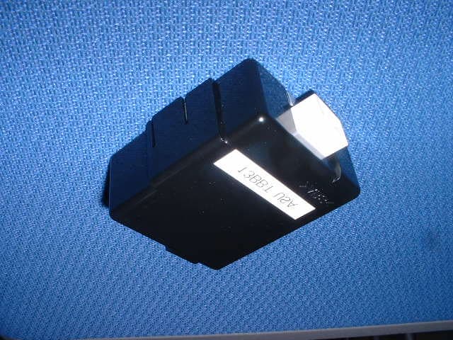
Click to zoom
Application Details
- Equipment Class
- CYY - Communications Receiver used w/Pt 15 Transmitter
- Date of Grant
- May 21, 2002
- Application Purpose
- Original Equipment
- Date of Application
- May 21, 2002
- Equipment Note
- Remote Keyless Entry System Receiver
- Frequency Range
- 314.35000000 - 314.35000000
- Company
- Denso Corporation
- Country
- Japan
Documents & Files
Document Text
Text extracted from the exhibit documents filed with the FCC. Open a document above to read the original.
Users Manual
Locking/Unlocking the doors INSTRUCTIONS When you push the ‘Lock’ button on the key, all the doors can be locked from outside the vehicle. Make sure all the doors are locked when you leave the vehicle. When you push the ‘Unlock’ button on the key, all the doors can be unlocked from outside the vehicle. (If applicable) When you push the ‘Trunk’ button on the key, the car trunk lid can be opened from outside the vehicle. (If applicable) When you push the ‘Power Back Door’ button on the key, the back door can be opened /closed from outside the vehicle. (If applicable) When you push the ‘Panic’ button on the key, alarms can be operated/unoperated from outside the vehicle. NOTE This device complies with Part 15 of the FCC Rules. Operation is subject to the following two conditions: (1) this device may not cause harmful interference, and (2) this device must accept any interference received, including interference that may cause undesired operation. FCC WARNING Changes or modifications not expressly approved by the party responsible for compliance could void the user’s authority to operate the equipment.
Cover Letter(s)
American Telecommunications Certification Body Inc. 6731 Whittier Ave, McLean, VA 22101 May 16, 2002 RE: FCC ID: Hyq13bbt Attention: Ms. Hiroka Umeyama I have a few comments on this Application. 1 While a Super Heterodyne receiver does not need certification and can be DOC’d, if certification is sought, it must be tested in accordance with ANSI C63.4 par 12.1.1.1. ANSI specifies that a CW signal from a signal generator SHALL be used to cohere with the receiver frequency. Please note that the testing done in the report is not in accordance with ANSI C63.4 in this respect. Please provide data showing testing was done in accordance with ANSI C63.4. 2 If this is a part 15 subpart B digital device, the statement in 15.105 must be in the manual. 3 While it can be assumed that the antenna was present during radiated emissions, it is not stated in the report that the antenna was connected. Please verify that the antenna was connected to the antenna terminals or that a resistive network was connected. If a resistive network was connected, then antenna terminal measurements must be made. Please clarify. Dennis Ward mailto:[email protected] The items indicated above must be submitted before processing can continue on the above referenced application. Failure to provide the requested information may result in application termination. Correspondence should be considered part of the permanent submission and may be viewed from the Internet after a Grant of Equipment Authorization is issued. Please do not respond to this correspondence using the email reply button. In order for your response to be processed expeditiously, you must submit your documents through the AmericanTCB.com website. Also, please note that partial responses increase processing time and should not be submitted. Any questions about the content of this correspondence should be directed to the sender.
Cover Letter(s)
A-PEX INTERNATIONAL CO., LTD. EMC HEAD OFFICE DIVISION 4383-326 Asama-cho, Ise-shi, Mie-ken 516-0021 Japan TEL:0596-24-8116 / FAX:0596-24-8124 Date: May 22, 2002 Re: Denso Corporation FCC ID: HYQ13BBT Dear Mr. Dennis Ward, Please find the following replies to your comments dated May 16, 2002; 1) We added the statement at page 5 and 6 in the report -Page 5 Section 4.1: we added (transmitting by exclusive used key) to explain Operation mode. -Page 5 Section 4.2: we added brief drawing of transmitter. -Page 6: We put transmitter’s details an addition to support equipment field. 2) This is not digital device, so that this device does not require the statement in Section15.105. 3) The Antenna is built-in type and included in the device already. 4) Please find the re-submitted photos of Setup in the filing. Keijiro Kumagai (Mr.) A-Pex International Co., Ltd.
External Photos
External Photo Denso Corporation FCC ID: HYQ13BBT Model Name: 13 BBT Front View Bottom View External Photo Denso Corporation FCC ID: HYQ13BBT Model Name: 13 BBT Over View
ID Label/Location Info
7 7. Marking location and layout Scale : free Note. Compliance statement of marking will not be changed. But marking layout, size and other indications maybe changed.
ID Label/Location Info
7 7. Marking location and layout Scale : free Note. Compliance statement of marking will not be changed. But marking layout, size and other indications maybe changed. <Front view>
Internal Photos
Internal Photo Denso Corporation FCC ID: HYQ13BBT Model Name: 13 BBT Front View Rear View
Operational Description
2 2. Technical description of the system 2.1 Type number -Receiver : 13BBT 2.2 Specifications of receiver -Nominal frequency : 314.35MHz -Micro computer clock frequency : 3.86 MHz -Type of receiving system : Super-heterodyne -Power Supply - Nominal supply voltage : 12 VDC (vehicle battery) -Antenna : Built-in type (Fixed) 3 3.Outline of the system 3.1 Description of the system operation This system is mainly used for locking or unlocking the doors of the vehicle. The transmitter sends a radio wave signal while the button is pushed. The receiver becomes active in response to the signal from the transmitter. 3.2 Installation in vehicle The receiver is installed inside the vehicle.
Test Report
Test report No. : 22HE0022-HO-2A Page : 2 of 12 Issued date : May 20, 2002 FCC ID : HYQ13BBT A-PEX International Co., Ltd.EMC Head Office Division. 4383-326 Asama-cho, Ise-shi, Mie-ken 516-0021 JAPAN Telephone: +81 596 24 8116 Facsimile: +81 596 24 8124 CONTENTS PAGE SECTION 1: Client information 3 SECTION 2: Equipment under test (E.U.T.) 3 SECTION 3: Test specification, procedures and results 4 SECTION 4: Operation of E.U.T. during testing 5 SECTION 5: Radiated emission 7 APPENDIX 1: Photographs of test setup 8 APPENDIX 2: Test instruments 8 APPENDIX 3: Data of EMI test 8 Test report No. : 22HE0022-HO-2A Page : 3 of 12 Issued date : May 20, 2002 FCC ID : HYQ13BBT A-PEX International Co., Ltd.EMC Head Office Division. 4383-326 Asama-cho, Ise-shi, Mie-ken 516-0021 JAPAN Telephone: +81 596 24 8116 Facsimile: +81 596 24 8124 SECTION 1: Client information Company name : DENSO CORPORATION Trade name : DENSO CORPORATION Address : 1-1 syowa-cho, kariya-shi, Aichi-ken. 448-8661 Japan Telephone Number : +81-566-61-4720 Facsimile Number : +81-566-25-4915 Contact Person : KUNIHIRO MIYAUCHI SECTION 2: Equipment under test (E.U.T.) 2.1 Identification of E.U.T. Type of Equipment : Remote Keyless Entry System (Receiver) Model No. : 13BBT Serial No. : 013 Rating : 12V DC (Vehicle Battery) Country of Manufacture : JAPAN Receipt Date of Sample : April 19, 2002 Condition of EUT : Engineering prototype 2.2 Product Description Model: 13BBT Remote Keyless Entry System (Receiver) is mainly used for locking or unlocking the doors of the vehicle. They are referred to as the EUT in this report. Type of receiver : Super Heterodyne Receiving Frequency : 314.35MHz Local Oscillator Frequency : 303.65MHz Intermediate Frequency : 10.7MHz Other Clock Frequency : 3.86MHz Information antenna : Built-in Type (Fixed) Operation Voltage : DC 12V Test report No. : 22HE0022-HO-2A Page : 4 of 12 Issued date : May 20, 2002 FCC ID : HYQ13BBT A-PEX International Co., Ltd.EMC Head Office Division. 4383-326 Asama-cho, Ise-shi, Mie-ken 516-0021 JAPAN Telephone: +81 596 24 8116 Facsimile: +81 596 24 8124 SECTION 3: Test specification, procedures and results 3.1 Test Specification Test Specification : FCC Part 15 Subpart B Title : FCC 47CFR Part15 Radio Frequency Device Subpart B Unintentional Radiators 3.2 Procedures and results Item Test Procedure Specification DeviationWorst margin Result Conducted emission ANSI C63.4:2000 Section 15.107(a) Excluded * N/A N/A Radiated emission ANSI C63.4:2000 Section 15.109 (a) Class B N/A 6.4dB 60.73MHz Horizontal Complied * The test is not applicable since the EUT does not have AC Mains * These tests were performed without any deviations from test procedure except for additions or exclusions. 3.3 Confirmation A-PEX INTERNATIONAL hereby confirms that E.U.T., in the configuration tested, complies with the specifications FCC Part 15 Subpart B Section 15.109 (a). 3.4 Uncertainty Radiated Emission Test The measurement uncertainty (with a 95% confidence level) for this test using Biconical antenna is ±4.4dB. The measurement uncertainty (with a 95% confidence level) for this test using Logperiodic antenna is ±5.0dB. The data listed in this test report may exceed the test limit because it does not have enough margin. The data listed in this test report has enough margin. 3.5 Test location A-PEX International Co., Ltd. Head Office EMC Division. No.1 semi Anechoic Chamber, 19.2 x 11.2 x 7.7 m 4383-326 Asama-cho, Ise-shi, Mie-ken 516-0021 JAPAN Telephone: +81 596 24 8116 Facsimile: +81 596 24 8124 This site has been fully described in a report submitted to FCC office, and listed on February, 2002 (Registration number: 313583). *NVLAP Lab. code: 200572-0 3.6 Test Setup, Data of EMI & Test instruments, Refer to Appendix 1 to 3. Test report No. : 22HE0022-HO-2A Page : 5 of 12 Issued date : May 20, 2002 FCC ID : HYQ13BBT A-PEX International Co., Ltd.EMC Head Office Division. 4383-326 Asama-cho, Ise-shi, Mie-ken 516-0021 JAPAN Telephone: +81 596 24 8116 Facsimile: +81 596 24 8124 1 RDA GND +B B A C 2 D SECTION 4: Operation of E.U.T. during testing 4.1 Operating Modes The EUT exercise program used during radiated and conducted testing was designed to exercise the various system components in a manner similar to typical use. The operating mode/system was as follows: Operation mode Receiving (transmitting by exclusive used key) Justification: The system was configured in typical fashion (as a customer would normally use it) for testing. 4.2 Configuration and peripherals Front view 1 2 A C RDA GND +B B D Top view Test report No. : 22HE0022-HO-2A Page : 6 of 12 Issued date : May 20, 2002 FCC ID : HYQ13BBT A-PEX International Co., Ltd.EMC Head Office Division. 4383-326 Asama-cho, Ise-shi, Mie-ken 516-0021 JAPAN Telephone: +81 596 24 8116 Facsimile: +81 596 24 8124 Description of EUT No. Item Model number Serial number Manufacturer FCC ID A Receiver 13BBT 013 DENSO HYQ13BBT S upport equipment No. Item Model number Serial number Manufacturer FCC ID B Check bench - 001 DENSO N/A C Car Battery B19L 161001C Panasonic N/A D Transmitter 12BBT 002 DENSO HYQ12BBT List of cables used No. Name Length (m) Shield Remark Extended harness 2.0 N Polyvinyl chloride DC Power Cable 1.0 N Polyvinyl chloride Test report No. : 22HE0022-HO-2A Page : 7 of 12 Issued date : May 20, 2002 FCC ID : HYQ13BBT A-PEX International Co., Ltd.EMC Head Office Division. 4383-326 Asama-cho, Ise-shi, Mie-ken 516-0021 JAPAN Telephone: +81 596 24 8116 Facsimile: +81 596 24 8124 SECTION 5: Radiated emission 5.1 Operating environment The test was carried out in a No.1 semi Anechoic Chamber, 19.2 x 11.2 x 7.7 m. Temperature : See data Humidity : See data 5.2 Test configuration EUT was placed on a platform of nominal size, 1m by 1.5m, raised 80cm above the conducting ground plane. The EUT was set on the center of the tabletop and the rear the peripheral was aligned and flushed with rear of tabletop. Test was made with the antenna positioned in both the horizontal a…
Text truncated - open the document above for the full version.
Test Setup Photos
Test report No.: 22HE0022-HO-2 Page : 9 of 12 Issued date : April 26, 2002 FCC ID : HYQ13BBT A-PEX International Co., Ltd.EMC Head Office Division. 4383-326 Asama-cho, Ise-shi, Mie-ken 516-0021 JAPAN Telephone: +81 596 24 8116 Facsimile: +81 596 24 8124 APPENDIX 1: Photographs of test setup Radiated emission
Contact Information
Applicant
Keijiro Kumagai(Manager)
Technical Contact
A-Pex International Co., Ltd.Hiroka Umeyama
[email protected]+81-596-24-8116
4383-326 Asama-cho, · Ise-Shi, Mie-ken · Japan
Non-Technical Contact
A-Pex International Co., Ltd.Kanako Sanda
[email protected]+81-596-24-8116
Test Firm
UL Japan, IncMitsuru Fujimura
Technical Specifications
| # | Rule Parts | Frequency Range | Power Output |
|---|---|---|---|
| 1 | 15B | 314.35 MHz - 314.35 MHz | - |
Other Applications from Denso Corporation
HYQDNILR001
Aug 04, 2026LiDsEYE
Equipment Class
JAB - Part 15 Class B Digital DeviceHYQDNMWR020
Mar 27, 2026Millimeter Wave Radar Sensor
Equipment Class
VRD - Part 95 Vehicular Radar SystemsHYQDNMWR021
Mar 10, 2026Millimeter Wave Radar Sensor
Equipment Class
VRD - Part 95 Vehicular Radar SystemsHYQ23ABR
Mar 05, 2026Remote Keyless Entry System and TPMS (Receiver)
Equipment Class
CYY - Communications Receiver used w/Pt 15 TransmitterHYQDNMWR018RAM
Oct 10, 2024Millimeter Wave Radar Sensor
Equipment Class
VRD - Part 95 Vehicular Radar Systems