HYQ13BDCRemote Keyless Entry System - Receiver
Denso Corporation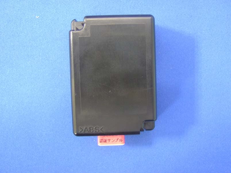
Click to zoom
Application Details
- Equipment Class
- CYY - Communications Receiver used w/Pt 15 Transmitter
- Date of Grant
- Aug 08, 2007
- Application Purpose
- Original Equipment
- Date of Application
- Aug 08, 2007
- Equipment Note
- Remote Keyless Entry System - Receiver
- Frequency Range
- 314.35000000 - 314.35000000
- Company
- Denso Corporation
- Country
- Japan
Documents & Files
Document Text
Text extracted from the exhibit documents filed with the FCC. Open a document above to read the original.
Users Manual
Product Description This system is mainly used for locking or unlocking the doors of the vehicle. The transmitter sends a radio wave signal while the button is pushed. The receiver becomes active in response to the signal from the transmitter. NOTE This device complies with Part 15 of the FCC Rules. Operation is subject to the following two conditions: (1) this device may not cause harmful interference, and (2) this device must accept any interference received, including interference that may cause undesired operation. NOTICE This equipment has been tested and found to comply with the limits for a Class B digital device, pursuant to Part 15 of the FCC Rules. These limits are designed to provide reasonable protection against harmful interference in a residential installation. This equipment generates, uses and can radiate radio frequency energy and, if not installed and used in accordance with the instructions, may cause harmful interference to radio communications. However, there is no guarantee that interference will not occur in a particular installation. If this equipment does cause harmful interference to radio or television reception, which can be determined by turning the equipment off and on, the user is encouraged to try to correct the interference by one or more of the following measures: -Reorient or relocate the receiving antenna. -Increase the separation between the equipment and receiver. -Connect the equipment into an outlet on a circuit different from that to which the receiver is connected. -Consult the dealer or an experienced radio-TV technician for help. FCC WARNING Changes or modifications not expressly approved by the party responsible for compliance could void the user’s authority to operate the equipment.
External Photos
External Photo DENSO CORPORATION Remote Keyless Entry System (Receiver) [Model: 13BDC] FCC ID: HYQ13BDC Front Rear External Photo DENSO CORPORATION Remote Keyless Entry System (Receiver) [Model: 13BDC] FCC ID: HYQ13BDC Top Bottom External Photo DENSO CORPORATION Remote Keyless Entry System (Receiver) [Model: 13BDC] FCC ID: HYQ13BDC Right Left
ID Label/Location Info
Label drawing and Label location Scale: free Note. Compliance statement of marking will not be changed. But marking layout, size and other indications maybe hd Fig. Marking location and layout of Receiver (50) (70) 13BDC 13BDC 13BDC
Internal Photos
Internal Photo DENSO CORPORATION Remote Keyless Entry System (Receiver) [Model: 13BDC] FCC ID: HYQ13BDC Internal(Top) Internal(Bottom) Internal Photo DENSO CORPORATION Remote Keyless Entry System (Receiver) [Model: 13BDC] FCC ID: HYQ13BDC Internal with Antenna
Test Report
Test report No. : 27KE0267-HO-A Page : 2 of 12 Issued date : July 12, 2007 FCC ID : HYQ13BDC UL Japan, Inc. Head Office EMC Lab. 4383-326 Asama-cho, Ise-shi, Mie-ken 516-0021 JAPAN Telephone : +81 596 24 8116 Facsimile : +81 596 24 8124 CONTENTS PAGE SECTION 1: Client information............................................................................................. 3 SECTION 2: Equipment under test (E.U.T.) ........................................................................ 3 SECTION 3: Test specification, procedures & results ......................................................... 4 SECTION 4: Operation of E.U.T. during testing ................................................................. 6 SECTION 5: Radiated Emission ............................................................................................ 7 APPENDIX 1: Photographs of test setup............................................................................... 8 Radiated Emission ......................................................................................................................... 8 Worst Case Position (Horizontal: X-axis /Vertical: X-axis) ...................................................... 9 APPENDIX 2: Data of EMI test ........................................................................................... 10 Radiated Emission ....................................................................................................................... 10 APPENDIX 3: Test instruments ........................................................................................... 12 Test report No. : 27KE0267-HO-A Page : 3 of 12 Issued date : July 12, 2007 FCC ID : HYQ13BDC UL Japan, Inc. Head Office EMC Lab. 4383-326 Asama-cho, Ise-shi, Mie-ken 516-0021 JAPAN Telephone : +81 596 24 8116 Facsimile : +81 596 24 8124 SECTION 1: Client information Company Name : DENSO CORPORATION Address : 1-1 Showa-cho, Kariya-city, Aichi-prefecture, 448-8661, Japan SECTION 2: Equipment under test (E.U.T.) 2.1 Identification of E.U.T. Type of Equipment : Remote Keyless Entry System (Receiver) Model No. : 13BDC Serial No. : 001 Country of Manufacture : Japan Receipt Date of Sample : June 25, 2007 Condition of EUT : Engineering prototype (Not for Sale: This sample is equivalent to mass-produced items.) Modification of EUT : No modification by the test lab. 2.2 Product Description Model No. 13BDC is the Remote Keyless Entry System (Receiver). Nominal frequency : 314.35MHz Oscillator frequency : 40.63125MHz (Crystal) Type of receiving system : Super-heterodyne Power Supply : DC12V (Nominal supply voltage) Antenna : Built-in type (Fixed) Type of modulation : ASK FCC15.111(b ) The receiving antenna (of this EUT) is installed inside the EUT and cannot be removed. Therefore, this EUT complies with the requirement in section 15.111(b). Test report No. : 27KE0267-HO-A Page : 4 of 12 Issued date : July 12, 2007 FCC ID : HYQ13BDC UL Japan, Inc. Head Office EMC Lab. 4383-326 Asama-cho, Ise-shi, Mie-ken 516-0021 JAPAN Telephone : +81 596 24 8116 Facsimile : +81 596 24 8124 SECTION 3: Test specification, procedures & results 3.1 Test specification Test Specification : FCC Part 15 Subpart B 2007 Title : FCC 47CFR Part15 Radio Frequency Device Subpart B Unintentional Radiators 3.2 Procedures and results Item Test Procedure Limits Deviation Worst margin Result Conducted emission ANSI C63.4: 2003 7. AC powerline conducted emission measurements Receiver N/A *1) N/A N/A Radiated emission ANSI C63.4: 2003 8. Radiated emission measurements Receiver N/A 17.3dB, QP 325.047MHz, Horizontal Complied *Note: UL Japan, Inc.’s EMI Work Procedure QPM05. *1)The test is not applicable since the EUT is not the device that is designed to be connected to the public utility (AC) power line. *These tests were performed without any deviations from test procedure except for additions or exclusions. 3.3 Additions or deviations to standards No addition, deviation, nor exclusion has been made from standards. 3.4 Uncertainty The following uncertainties have been calculated to provide a confidence level of 95% using a coverage factor k=2. Radiated Emission The measurement uncertainty for this test using Loop antenna is ±4.41dB(3m). The measurement uncertainty for this test using Biconical antenna is ±4.59dB(3m). The measurement uncertainty for this test using Logperiodic antenna is ±4.62dB(3m). The measurement uncertainty for this test using Horn antenna is ±5.27dB. The data listed in this test report has enough margin, more than the site margin. Test report No. : 27KE0267-HO-A Page : 5 of 12 Issued date : July 12, 2007 FCC ID : HYQ13BDC UL Japan, Inc. Head Office EMC Lab. 4383-326 Asama-cho, Ise-shi, Mie-ken 516-0021 JAPAN Telephone : +81 596 24 8116 Facsimile : +81 596 24 8124 3.5 Test Location UL Japan, Inc. Head Office EMC Lab. *NVLAP Lab. code: 200572-0 4383-326 Asama-cho, Ise-shi, Mie-ken 516-0021 JAPAN Telephone : +81 596 24 8116 Facsimile : +81 596 24 8124 FCC Registration Number IC Registration Number Width x Depth x Height (m) Size of reference ground plane (m) / horizontal conducting plane Other rooms No.1 semi-anechoic chamber 313583 IC4247A 19.2 x 11.2 x 7.7m 7.0 x 6.0m Preparation room No.2 semi-anechoic chamber 655103 IC4247A-2 7.5 x 5.8 x 5.2m 4.0 x 4.0m - No.3 semi-anechoic chamber 148738 IC4247A-3 12.0 x 8.5 x 5.9m 6.8 x 5.75m No.3 shielded room - - 4.0 x 6.0 x 2.7m N/A - No.4 semi-anechoic chamber 134570 IC4247A-4 12.0 x 8.5 x 5.9m 6.8 x 5.75m - No.4 shielded room - - 4.0 x 6.0 x 2.7m N/A - No.5 semi-anechoic chamber - - 6.0 x 6.0 x 3.9m 6.0 x 6.0m - No.6 shielded room - - 4.0 x 4.5 x 2.7m 4.75 x 5.4 m - No.6 measurement room - - 4.75 x 5.4 x 3.0m 4.75 x 4.15 m - No.7 shielded room - - 4.7 x 7.5 x 2.7m 4.7 x 7.5m - No.8 measurement room - - 3.1 x 5.0 x 2.7m N/A - * Size of vertical conducting plane (for Conducted Emission test) : 2.0 x 2.0m for No.1, No.2, No.3, and No.4 semi-anechoic chambers and No.3 and No.4 shielded rooms. 3.6 Test…
Text truncated - open the document above for the full version.
Test Setup Photos
Test report No. : 27KE0267-HO-A Page : 8 of 12 Issued date : July 12, 2007 FCC ID : HYQ13BDC UL Japan, Inc. Head Office EMC Lab. 4383-326 Asama-cho, Ise-shi, Mie-ken 516-0021 JAPAN Telephone : +81 596 24 8116 Facsimile : +81 596 24 8124 APPENDIX 1: Photographs of test setup Radiated Emission Front Rear Test report No. : 27KE0267-HO-A Page : 9 of 12 Issued date : July 12, 2007 FCC ID : HYQ13BDC UL Japan, Inc. Head Office EMC Lab. 4383-326 Asama-cho, Ise-shi, Mie-ken 516-0021 JAPAN Telephone : +81 596 24 8116 Facsimile : +81 596 24 8124 Worst Case Position (Horizontal: X-axis /Vertical: X-axis) EUT-X-axis EUT-Y-axis EUT-Z-axis
Contact Information
Applicant
Keijiro Kumagai(Manager)
Technical Contact
UL Japan IncMitsuru Fujimura
[email protected]81-596-24-8116
4383-326 Asama-cho · Ise-shi, Mie-ken · Japan
Non-Technical Contact
UL Japan IncKeijiro Kumagai
[email protected]81-596-24-8116
Test Firm
UL Japan, IncMitsuru Fujimura
Technical Specifications
| # | Rule Parts | Frequency Range | Power Output |
|---|---|---|---|
| 1 | 15B | 314.35 MHz - 314.35 MHz | - |
Other Applications from Denso Corporation
HYQDNILR001
Aug 04, 2026LiDsEYE
Equipment Class
JAB - Part 15 Class B Digital DeviceHYQDNMWR020
Mar 27, 2026Millimeter Wave Radar Sensor
Equipment Class
VRD - Part 95 Vehicular Radar SystemsHYQDNMWR021
Mar 10, 2026Millimeter Wave Radar Sensor
Equipment Class
VRD - Part 95 Vehicular Radar SystemsHYQ23ABR
Mar 05, 2026Remote Keyless Entry System and TPMS (Receiver)
Equipment Class
CYY - Communications Receiver used w/Pt 15 TransmitterHYQDNMWR018RAM
Oct 10, 2024Millimeter Wave Radar Sensor
Equipment Class
VRD - Part 95 Vehicular Radar Systems