HYQDECS001Electrostatic Capacity sensor
Denso Corporation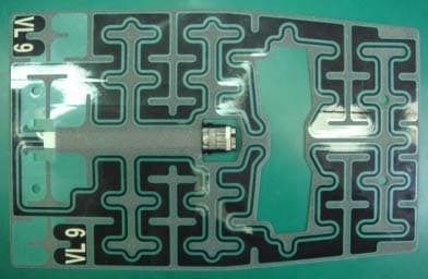
Click to zoom
Application Details
- Equipment Class
- 8CC - Part 18 Consumer Device
- Date of Grant
- Jul 24, 2013
- Application Purpose
- Original Equipment
- Date of Application
- Jul 24, 2013
- Equipment Note
- Electrostatic Capacity sensor
- Frequency Range
- 0.08300000 - 0.08300000
- Company
- Denso Corporation
- Country
- Japan
Documents & Files
Document Text
Text extracted from the exhibit documents filed with the FCC. Open a document above to read the original.
Users Manual
Manual Requirement of FCC Our product (DECS001) is one of vehicle parts, which is installed in the passenger seat. We will supply the user’s manual that include statements and instructions in accordance with FCC requirements. NOTE This device compiles with Part 18 of the FCC Rules. This device may cause interference. If this device causes interference, please consult the nearest SUBARU dealer for maintenance of the system. Black plate (65,1) 北 米 Model "A1120BE-A" EDITED: 2011/ 6/ 16 & SUBARU advanced frontalairbag system S01AH02 Your vehicle is equipped with a SUBARUadvanced frontal airbag system that com-plies with the new advanced frontal airbagrequirements in the amended FederalMotor Vehicle Safety Standard (FMVSS)No. 208.The SUBARU advanced frontal airbagsystem automatically determines the de-ployment force of the driver ’ s SRS frontal airbag at the time of deployment as well aswhether or not to activate the frontpassenger ’ s SRS frontal airbag and, if activated, the deployment force of theSRS frontal airbag at the time of deploy-ment.Your vehicle has warning labels on thedriver ’ s and front passenger ’ s sun visors beginning with the phrase “ EVEN WITH ADVANCED AIR BAGS ” and a tag attached to the glove box lid beginningwith the phrase “ Even with Advanced Air Bags ” . Make sure that you carefully read the instructions on the warning labels andtag.Always wear your seatbelt. The SUBARUadvanced frontal airbag system is asupplemental restraint system and mustbe used in combination with a seatbelt. Alloccupants should wear a seatbelt or beseated in an appropriate child restraint system.The driver ’ s SRS frontal airbag is stowed in the center portion of the steering wheel.The front passenger ’ s SRS frontal airbag is stowed near the top of the dashboardunder an “ SRS AIRBAG ” mark. Also, the driver ’ s knee airbag is stowed in the bottom of the steering column.In a moderate to severe frontal collision,the following components deploy.. SRS frontal airbag for driver . SRS frontal airbag for front passenger . Knee airbag for driver These components supplement the seat-belts by reducing the impact to theoccupant ’ s head, chest and knees. WARNING NEVER INSTALL A REARWARD FA-CING CHILD SEAT IN THE FRONTSEAT. DOING SO RISKS SERIOUSINJURY OR DEATH TO THE CHILDBY PLACING THE CHILD ’ S HEAD TOO CLOSE TO THE SRS AIRBAG. WARNING Never allow a child to stand up, or tokneel on the front passenger ’ s seat. The SRS airbag deploys with con-siderable force and can injure oreven kill the child. Seat, seatbelt and SRS airbags 1-39 – CONTINUED – 1 Black plate (66,1) 北 米 Model "A1120BE-A" EDITED: 2011/ 6/ 16 1-40 Seat, seatbelt and SRS airbags WARNING Never hold a child on your lap or inyour arms. The SRS airbag deployswith considerable force and caninjure or even kill the child. WARNING The SRS airbag deploys with con-siderable speed and force. Occu-pants who are out of proper positionwhen the SRS airbag deploys couldsuffer very serious injuries. Be-cause the SRS airbag needs enoughspace for deployment, the drivershould always sit upright and wellback in the seat as far from thesteering wheel as practical whilestill maintaining full vehicle controland the front passenger shouldmove the seat as far back aspossible and sit upright and wellback in the seat.It is also important to wear your seatbelt to help avoid injuries thatcan result when the SRS airbagcontacts an occupant not in properposition such as one thrown towardthe front of the vehicle during pre-accident braking. WARNING . Do not put any objects over the steering wheel pad and dash-board. If the SRS frontal airbagdeploys, these objects could in-terfere with its proper operationand could be propelled inside thevehicle, causing injury. . Do not put any objects under the driver ’ s side of the instrument Black plate (67,1) 北 米 Model "A1120BE-A" EDITED: 2011/ 6/ 21 panel. If the knee airbag deploys,those objects could interfere withits proper operation and could bepropelled inside the vehicle,causing injury. . The key must not be attached to heavy, sharp or hard acces-sories, or another key. If the kneeairbag deploys, those objectscould interfere with its properoperation and could be propelledinside the vehicle and causeinjury. WARNING Do not attach accessories to thewindshield, or fit an extra-wide mir- ror over the rear view mirror. If theSRS airbag deploys, those objectscould become projectiles that couldseriously injure vehicle occupants. ! Driver ’ s SRS frontal airbag S01AH0201 The driver ’ s SRS frontal airbag uses a dual stage inflator. The inflator operates indifferent ways depending on the severityof impact.Have the system inspected by yourSUBARU dealer immediately if the SRSairbag system warning light illuminates. NOTEThe driver ’ s SRS side airbag and SRS curtain airbag are not controlled by theSUBARU advanced frontal airbag sys-tem.! Front passenger ’ s SRS frontal air- bag S01AH0202 The front passenger ’ s SRS frontal airbag uses a dual stage inflator. The inflatoroperates in different ways depending onthe severity of impact.The occupant detection system sensor isinstalled under the seat upholstery andmonitors the position and posture of thefront passenger. Using this information,the occupant detection system determines whether the front passenger ’ s SRS frontal impact airbag should be deployed or not.The occupant detection system may notinflate the front passenger ’ s SRS frontal airbag even when the driver ’ s SRS frontal airbag deploys. This is normal. In thiscase, although the front passenger ’ s SRS frontal airbag does not operate, the frontpassenger ’ s seatbelt pretensioner oper- ates with the driver ’ s seatbelt preten- sioner. For details about the seatbeltpretensioner, refer to “ s01af Front seatbelt pretensioners ” F 1-20 . Observe the following precautions. Failureto do so may prevent the SUBARUadvanced frontal airbag system fromfunctioning correctly or cause the systemto fail.. Do not apply any strong impact to the front…
Text truncated - open the document above for the full version.
Cover Letter(s)
Date: July 9, 2013 UL Verification Services Inc. 47173 Benicia Street, Fremont, CA 94538 Reference: Applicant: DENSO CORPORATION FCC ID: HYQDECS001 To whom it may concern: We, the undersigned, hereby authorize Yoshinobu Asai of Application Section, WiSE Japan, UL Verification Service, UL Japan, Inc. to act on our behalf in all manners relating to application for equipment authorization, including signing of all documents relating to these matters. Any and all acts carried out by UL Japan, Inc. on our behalf shall have the same effect as acts of our own. We, the undersigned, hereby certify that we are not subject to a denial of federal benefits, that includes FCC benefits, pursuant to Section 5301 of the Anti-Drug Abuse Act of 1988, 21 U.S.C. 853(a). This authorization is valid until further written notice from the applicant. The application for the subject equipment has not been submitted to another TCB for certification. Sincerely Yours, Kazuo Sakakibara Manager DENSO CORPORATION 1-1,Showa-cho, Kariya-shi, Aichi-ken, 448-8661, Japan Tel : +81-566-25-5947 Fax : +81-566-25-4548
Cover Letter(s)
UL Verification Services Inc. 47173 Benicia Street, Fremont, CA 94538 Subject: Request for Confidentiality FCC ID: HYQDECS001 To Whom It May Concern: Pursuant to the provisions of Sections 0.457 and 0.459 of the Commission’s rules (47 CFR §§ 0.457, 0.459), we are requesting the Commission to withhold the following attachments as confidential document from public disclosure indefinitely. Schematic Diagram Block Diagram Theory of Operation Above mentioned document contains detailed system and equipment description are considered as proprietary information in operation of the equipment. The public disclosure of above documents might be harmful to our company and would give competitor an unfair advantage in the market. Best Regards Kazuo Sakakibara Manager DENSO CORPORATION July 9, 2013 1-1,Showa-cho, Kariya-shi, Aichi-ken, 448-8661, Japan Tel : +81-566-25-5947 Fax : +81-566-25-4548
External Photos
4 9 Jul.01/2013 THIS INFORMATION IS THE EXCLUSIVE PROPERTY OF DENSO CORPORATION. WITHOUT THEIR CONSENT, IT MAY NOT BE REPRODUCED OR GIVEN TO THIRD PARTIES. Driving Assist & Safety Eng. Division.3 Confidential 5 9 Jul.01/2013 THIS INFORMATION IS THE EXCLUSIVE PROPERTY OF DENSO CORPORATION. WITHOUT THEIR CONSENT, IT MAY NOT BE REPRODUCED OR GIVEN TO THIRD PARTIES. Driving Assist & Safety Eng. Division.3 Confidential
ID Label/Location Info
7 9 Jul.01/2013 THIS INFORMATION IS THE EXCLUSIVE PROPERTY OF DENSO CORPORATION. WITHOUT THEIR CONSENT, IT MAY NOT BE REPRODUCED OR GIVEN TO THIRD PARTIES. Driving Assist & Safety Eng. Division.3 Confidential
Internal Photos
1 1 Jul.12/2013 THIS INFORMATION IS THE EXCLUSIVE PROPERTY OF DENSO CORPORATION. WITHOUT THEIR CONSENT, IT MAY NOT BE REPRODUCED OR GIVEN TO THIRD PARTIES. Driving Assist & Safety Eng. Division.3 Confidential 6 9 Jul.01/2013 THIS INFORMATION IS THE EXCLUSIVE PROPERTY OF DENSO CORPORATION. WITHOUT THEIR CONSENT, IT MAY NOT BE REPRODUCED OR GIVEN TO THIRD PARTIES. Driving Assist & Safety Eng. Division.3 Confidential
Test Report
Test report No. : 10018574H-A-R1 Page : 2 of 13 Issued date : June 25, 2013 Revised date : July 11, 2013 FCC ID : HYQDECS001 UL Japan, Inc. Head Office EMC Lab. 4383-326 Asama-cho, Ise-shi, Mie-ken 516-0021 JAPAN Telephone : +81 596 24 8999 Facsimile : +81 596 24 8124 REVISION HISTORY Original Test Report No.: 10018574H-A Revision Test report No. Date Page revised Contents - (Original) 10018574H-A June 25, 2013 - Based on test report: 30LE0269-HO-A 1 10018574H-A-R1 July 11, 2013 P. 4 Correction of Clock frequency in Section 2.2. Addition of Operating frequency in Section 2.2. 1 10018574H-A-R1 July 11, 2013 P. 4 Addition of the following sentence in Section 2.2. Maximum amplitude voltage: 1.0Vp-p (+/- 0.1V) AC (Offset 2.5V +/-0.15V DC) 1 10018574H-A-R1 July 11, 2013 P. 8 Addition of applied Limit and calculating formula of Limit Test report No. : 10018574H-A-R1 Page : 3 of 13 Issued date : June 25, 2013 Revised date : July 11, 2013 FCC ID : HYQDECS001 UL Japan, Inc. Head Office EMC Lab. 4383-326 Asama-cho, Ise-shi, Mie-ken 516-0021 JAPAN Telephone : +81 596 24 8999 Facsimile : +81 596 24 8124 CONTENTS PAGE SECTION 1: Customer information ....................................................................................... 4 SECTION 2: Equipment under test (E.U.T.) ......................................................................... 4 SECTION 3: Test specification, procedures & results .......................................................... 5 SECTION 4: Operation of E.U.T. during testing .................................................................. 7 SECTION 5: Radiated Emission ............................................................................................. 8 APPENDIX 1: Data of EMI test ............................................................................................ 10 Radiated Emission .......................................................................................................................... 10 APPENDIX 2: Test instruments ............................................................................................ 12 APPENDIX 3: Photographs of test setup ............................................................................. 13 Radiated Emission .......................................................................................................................... 13 Test report No. : 10018574H-A-R1 Page : 4 of 13 Issued date : June 25, 2013 Revised date : July 11, 2013 FCC ID : HYQDECS001 UL Japan, Inc. Head Office EMC Lab. 4383-326 Asama-cho, Ise-shi, Mie-ken 516-0021 JAPAN Telephone : +81 596 24 8999 Facsimile : +81 596 24 8124 SECTION 1: Customer information Company Name : DENSO CORPORATION Address : 1-1 Showa-cho, Kariya-shi, Aichi-ken, 448-8661 Japan Telephone Number : +81-566-25-5947 Facsimile Number : +81-566-25-4548 Contact Person : Koichiro Ukai SECTION 2: Equipment under test (E.U.T.) 2.1 Identification of E.U.T. Type of Equipment : Electrostatic Capacity sensor Model No. : DECS001 Serial No. : Refer to Section 4, Clause 4.2 Rating : DC12V Receipt Date of Sample : June 13, 2013 Country of Mass-production : Japan Condition of EUT : Production prototype (Not for Sale: This sample is equivalent to mass-produced items.) Modification of EUT : No Modification by the test lab 2.2 Product Description Model No: DECS001 is the Electrostatic Capacity sensor. Clock frequency in the system : CPU: 16MHz Custom IC: 4MHz Operating Frequency : 83.33kHz Maximum amplitude voltage : 1.0Vp-p (+/-0.1V) AC (Offset 2.5V +/-0.15V DC) Feature of EUT : This sensor is installed in the vehicle seat and used for detecting the object on the seat. <Contents of the change from original model> Original test report number of this report is 30LE0269-HO-A. The EUT is changed the specification from original model as below. - Change of electrode geometry - Change of software Test report No. : 10018574H-A-R1 Page : 5 of 13 Issued date : June 25, 2013 Revised date : July 11, 2013 FCC ID : HYQDECS001 UL Japan, Inc. Head Office EMC Lab. 4383-326 Asama-cho, Ise-shi, Mie-ken 516-0021 JAPAN Telephone : +81 596 24 8999 Facsimile : +81 596 24 8124 SECTION 3: Test specification, procedures & results 3.1 Test specification Test Specification : FCC Part 18 2002 Title : FCC 47CFR Part18 Industrial, scientific, and medical equipment 3.2 Procedures and results Item Test Procedure & Limits Deviation Worst margin Result Radiated emission Section 18.305 FCC/OST MP-5 N/A 14.6dB 0.16666MHz, PEAK, Horizontal Complied Conducted emission Section 18.307 FCC/OST MP-5 N/A N/A *1) N/A *Note: UL Japan, Inc.’s EMI Work Procedure 13-EM-W0420 and 13-EM-W0424. *1) The test is not applicable since the EUT is not the device that is designed to be connected to the public utility (AC) power line. 3.3 Addition to standard No addition, exclusion nor deviation has been made from the standard. 3.4 Uncertainty EMI The following uncertainties have been calculated to provide a confidence level of 95% using a coverage factor k=2. Test room (semi- anechoic chamber) Radiated emission (10m*)(+dB) 9kHz -30MHz 30MHz -300MHz 300MHz -1GHz No.1 4.2dB 5.0dB 4.8dB No.2 - - - No.3 - - - No.4 - - - *10m = Measurement distance Radiated emission test(10m) The data listed in this test report has enough margin, more than the site margin. Test report No. : 10018574H-A-R1 Page : 6 of 13 Issued date : June 25, 2013 Revised date : July 11, 2013 FCC ID : HYQDECS001 UL Japan, Inc. Head Office EMC Lab. 4383-326 Asama-cho, Ise-shi, Mie-ken 516-0021 JAPAN Telephone : +81 596 24 8999 Facsimile : +81 596 24 8124 3.5 Test Location UL Japan, Inc. Head Office EMC Lab. *NVLAP Lab. code: 200572-0 4383-326 Asama-cho, Ise-shi, Mie-ken 516-0021 JAPAN Telephone : +81 596 24 8999 Facsimile : +81 596 24 8124 FCC Registration Number IC Registration Number Width x Depth x Height (m) Size of reference ground plane (m) / horizontal conducting plane Other rooms No.1 semi-anechoic chamber 313583 2973C-1 19.2 x 11.2 x 7.7m 7.0 x 6.0m No.1 …
Text truncated - open the document above for the full version.
Test Setup Photos
Test report No. : 10018574H-A-R1 Page : 13 of 13 Issued date : June 25, 2013 Revised date : July 11, 2013 FCC ID : HYQDECS001 UL Japan, Inc. Head Office EMC Lab. 4383-326 Asama-cho, Ise-shi, Mie-ken 516-0021 JAPAN Telephone : +81 596 24 8999 Facsimile : +81 596 24 8124 APPENDIX 3: Photographs of test setup Radiated Emission Photo 1 Photo 2 End of Report
Contact Information
Applicant
Keijiro Kumagai(Manager)
Technical Contact
UL Japan, Inc.Takashi Nakazawa
[email protected]81-596-24-8116
4383-326 Asama-cho, Ise-shi · Mie-ken · Japan
Test Firm
UL Japan, Inc. Head office EMC Lab.Tetsuya Hashimoto
Technical Specifications
| # | Rule Parts | Frequency Range | Power Output |
|---|---|---|---|
| 1 | 18 | 0.083 MHz - 0.083 MHz | - |
Other Applications from Denso Corporation
HYQDNILR001
Aug 04, 2026LiDsEYE
Equipment Class
JAB - Part 15 Class B Digital DeviceHYQDNMWR020
Mar 27, 2026Millimeter Wave Radar Sensor
Equipment Class
VRD - Part 95 Vehicular Radar SystemsHYQDNMWR021
Mar 10, 2026Millimeter Wave Radar Sensor
Equipment Class
VRD - Part 95 Vehicular Radar SystemsHYQ23ABR
Mar 05, 2026Remote Keyless Entry System and TPMS (Receiver)
Equipment Class
CYY - Communications Receiver used w/Pt 15 TransmitterHYQDNMWR018RAM
Oct 10, 2024Millimeter Wave Radar Sensor
Equipment Class
VRD - Part 95 Vehicular Radar Systems