HYQDNMWR001Vehicle Radar System
Denso Corporation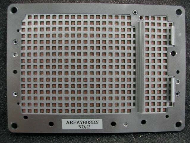
Click to zoom
Application Details
- Equipment Class
- FDS - Part 15 Field Disturbance Sensor
- Date of Grant
- Nov 10, 2003
- Application Purpose
- Original Equipment
- Date of Application
- Nov 10, 2003
- Equipment Note
- Vehicle Radar System
- Frequency Range
- 76000.00000000 - 77000.00000000
- Company
- Denso Corporation
- Country
- Japan
Documents & Files
Document Text
Text extracted from the exhibit documents filed with the FCC. Open a document above to read the original.
Users Manual
Manual Requirement of FCC / IC Our product (DNMWR001) is one of vehicle parts incorporated into the vehicle as the original equipment. Therefore we will not supply the user’s manual and service manual of the product. Although, we will request to describe on the vehicle user’s manual and service manual as following statement accordance with FCC and IC requirement to the vehicle manufacturer. 1. Requirement to User Manual 1.1. FCC Requirement 1.1.1. Accordance with 15.21 of FCC rule, we will describe on the user’s manual as following statement. 1.1.2. Accordance with FCC RF exposure of requirement, we will describe on the user’s manual as following statement. 1.2. IC Requirement 1.2.1. Accordance with RSS-210 of requirement, we will describe on the user’s manual as following statement. 2. Service manual Accordance with SAR requirement of FCC rule, we will describe on the service manual as following statement. Operation is subject to the following two conditions; (1) this device may not cause interference, and (2) this device must accept any interference received, including interference that may cause undesired operation of the device. (3) FCC WARNING Changes or modifications not expressly approved by the party responsible for compliance could void the user’s authority to operate the equipment. FCC RF exposure Information This device complies with the FCC RF exposure requirements. Caution : Radio Frequency Exposure This device comply with applicable FCC radio frequency exposure regulations, must be adjusted with a distance of at least 20cm (7.9 inches) between the RF aperture of device and the body of any person at all time during adjustment. To : XXXXXXXXXXXXXXX The following statements are FCC and IC requirement for user’s manual and service manual. Therefore, the following statements must be described on user’s manual and service manual. Please describe the following statements on your user’s manual and service manual. 1. Requirement statement for user’s manual requirement 1.1. FCC Requirement 1.2. IC Requirement 2. Requirement statement for service manual Note ; Above sheet is translated to English. In general, we will use Japanese version. Above sheet is draft version, so some changes may be occurred. But information contents are not changed. Operation is subject to the following two conditions; (1) this device may not cause interference, and (2) this device must accept any interference received, including interference that may cause undesired operation of the device. FCC WARNING Changes or modifications not expressly approved by the party responsible for compliance could void the user’s authority to operate the equipment. FCC RF exposure Information This device complies with the FCC RF exposure requirements. Caution : Radio Frequency Exposure This device comply with applicable FCC radio frequency exposure regulations, must be adjusted with a distance of at least 20cm (7.9 inches) between the RF aperture of device and the body of any person at all time during adjustment. 3. Outline of operation and Service manual Our product is one of vehicle parts incorporated into the vehicle as the original equipment. Therefore we will not supply the user’s manual and service manual of the product. We describe the operation and service method as followings. - Operation Our product will be stand-by radiating the radio frequency by vehicle ignition ON. And the product will radiate radio wave by stepping on the vehicle’s accelerator. - Service Our product is adjusted the axis of RF beam as following steps. 1. For the adjustment of vertical RF beam axis - The screw for vertical adjustment of Milli-wave radar sensor is turned by the wrench, and the vertical angle of RF beam is adjusted. 2. For the adjustment of Horizontal RF beam axis - The Ignition of vehicles is turned ON. - The inspection equipment is connected to vehicle. - Gap of a horizontal axis is checked according to the work procedure displayed on the screen of inspection equipment. - Based on an inspection result, a wrench turns and adjusts the right-and-left adjustment screw of Milli-wave radar sensor.
External Photos
CETECOM ICT Services GmbH Test report No.: 2-3314-01-01/03Date : 01.10.2003Page 60 of 73 Photo 8 EUT bottom view CETECOM ICT Services GmbH Test report No.: 2-3314-01-01/03Date : 01.10.2003Page 61 of 73 Photo 9 EUT side view CETECOM ICT Services GmbH Test report No.: 2-3314-01-01/03Date : 01.10.2003Page 64 of 73 Photo 12 EUT inside view antenna section front side CETECOM ICT Services GmbH Test report No.: 2-3314-01-01/03Date : 01.10.2003Page 65 of 73 Photo 13 EUT inside view antenna section back side CETECOM ICT Services GmbH Test report No.: 2-3314-01-01/03Date : 01.10.2003Page 67 of 73 Photo 15 EUT inside view without housing CETECOM ICT Services GmbH Test report No.: 2-3314-01-01/03Date : 01.10.2003Page 68 of 73 Photo 16 EUT inside view without housing CETECOM ICT Services GmbH Test report No.: 2-3314-01-01/03Date : 01.10.2003Page 69 of 73 Photo 17 EUT inside view without housing CETECOM ICT Services GmbH Test report No.: 2-3314-01-01/03Date : 01.10.2003Page 70 of 73 Photo 18 EUT inside view microwave module front side CETECOM ICT Services GmbH Test report No.: 2-3314-01-01/03Date : 01.10.2003Page 71 of 73 Photo 19 EUT inside view microwave module back side
RF Exposure Info
CETECOM ICT Services GmbH Test report No.: 2-3314-01-01/03Date : 01.10.2003Page 13 of 73 In the frequency range 33 GHz to 325 GHz, spurious frequencies are measured as power densities. For further remarks see section 1.). In order to simplify spurious measurements, the FMCW-modulation is disabled, and the EUT is operating as a CW transmitter. The RBW and VBW are set to such a value that spurious power levels clearly are readable above fundamental noise level. 4. Measurements of maximum safe level for radiated power density According to FCC § 1.1307, 1.1310, 2.1091, and 2.1093 and also according to ETSI/EN 301 091 measurements are carried out in order to evaluate the impact of human exposure to RF radiation. For this test the EUT is in normal operation mode: FMCW and normal pulse mode. The measurement is performed at 5 different distances: 4 m, 2 m, 1 m, 0.5 m, and 0.25 m. See ETSI test report 2-3314-01-02/03 page 15. The measurements are applicable only for far field conditions. The near field area extends to a distance of R (meters) and can be calculated from the following equation: R < 2 ∗ L 2 / λ with R = distance in meters, L = largest dimension of either receiving or transmitting horn antenna (L = 0.02 m), and λ = wavelength in meters. In case of 76 GHz (λ = 0.0039 m), the far field starts at R > 0.205 m. The peak power density is measured in 3 m distance as 7.5 μW/cm 2 (-21.25 dBmW/cm 2 ). Peak Power (EIRP)EIRP = PD ∗ 4π ∗ R 2 EIRP = 8.482 W (Peak) This is a PEP value which must be multiplied with the duty cycle correction factor (dcc) in order to get the average value. With t on = 9.412 ms, and t off = 90 ms. dcc= 20 ∗ log (t on / t off) dcc= -19.61 dB Average power (EIRP)eirp= 10 log (EIRP Peak) - dcc eirp= -10.32 dBW EIRP = 92.789 mW Limit of maximum ERP for frequencies above 1.5 GHz is 3 W. See FCC § 2.1091 RF Exposure for mobile conditions at R = 20 cm distance from EUT PD= EIRP average / (4π ∗ R 2 ) PD= 0.0184 mW/cm² Limit of maximum permissible exposure (MPE) for uncontrolled environment:1.0 mW/cm². See FCC § 1.1310.
Test Report
CETECOM ICT Services GmbH Radio Satellite Communication Untertürkheimer Straße 6–10, D-66117 Saarbrücken, Telephone +49 (0) 681 598 - 0 , Fax +49 (0) 681 598 – 9075 Test report No.: 2-3314-01-01/03This test report consists of 73 pagesPage 1 of 73 Recognized by the Federal Communications Commission and Industry Canada Anechoic chamber registration No.: 90462 (FCC) Anechoic chamber registration No.: 3463 (IC) TCB ID: DE0001 Accredited by the German Accreditation Council DAR–Registration Number TTI–P–G 166/98-30 Independent ETSI compliance test house ETSI Test report No.: 2-3314-01-01/03 Applicant: DENSO CORPORATION Type: DNMWR001 Test standard : FCC Part 15 CETECOM ICT Services GmbH Test report No.: 2-3314-01-01/03Date : 01.10.2003Page 2 of 73 Table of contentsPage 1.General information............................................................................3 1.1Notes....................................................................................................3 1.2Testing laboratory.................................................................................4 1.3Details of applicant................................................................................4 1.4Application details.................................................................................4 1.5Test item (EUT).....................................................................................5 1.6Technical data.......................................................................................5 1.6.1Operation conditions.............................................................................5 1.6.2Equipment under test............................................................................5 1.7Test standards......................................................................................6 2.Technical tests....................................................................................7 2.1Summary of test results........................................................................7 2.2Test environment..................................................................................7 2.3Measurement and test set-up...............................................................7 2.4Test equipment utilised and test set-up.........................................8 - 10 2.5Test results.........................................................................................11 2.5.1Test results overview..........................................................................11 2.5.2Remarks on methods of measurements ...................................................11 - 13 2.5.3Test results according to FCC in details.......................................14 - 20 3.Plots, graphs and data sheets..................................................21 - 52 4.Photographs...............................................................................53 - 73 CETECOM ICT Services GmbH Test report No.: 2-3314-01-01/03Date : 01.10.2003Page 3 of 73 1General information 1.1Notes The test results of this test report relate exclusively to the test item specified in 1.5. CETECOM ICT Services GmbH does not assume responsibility for any conclusions and generalisations drawn from the test results with regard to other specimens or samples of the type of the equipment represented by the test item . The test report may only be reproduced or published in full. Reproduction or publication of extracts from the report requires the prior written approval of the CETECOM ICT Services GmbH. Tester : DateNameSignature 31.07.03Manfred Paschwitz Technical responsibility for area of testing: DateNameSignature 31.07.03Klaus Kammerinke CETECOM ICT Services GmbH Test report No.: 2-3314-01-01/03Date : 01.10.2003Page 4 of 73 1.2Testing laboratory CETECOM ICT Services GmbH Untertürkheimerstraße 6–10P.O. Box 10 04 45 D-66117 Saarbrücken D-66004 Saarbrücken GermanyGermany Telephone:+ 49 (0) 681 598–0 Fax:+ 49 (0) 681 598–9075 e-mail:[email protected] Internet:http://www.cetecom.de Accredited testing laboratory Accredited by:Regulierungsbehörde für Telekommunikation und Post (RegTP) Listed by:Federal Communications Commission (FCC) Industry Canada (IC) AuthorityIdentification/Registration No. RegTPTTI-P-G 166/98-30 FCC90462 IC3463 Testing location, if different from CETECOM ICT Services GmbH: (Not applicable) 1.3Details of applicant Name:DENSO CORPORATION Street:1-1, Showa-cho Town:Kariya-shi Country:448-8661 Japan Tel.:+81-566-61-7294 Fax:+81-566-25-4683 Contact person Name:Noriyuki Tomioka Tel.:+81-566-61-7294 Fax:+81-566-25-4683 e-mail:noriyuki.tomioka/ndj@ndj 1.4Application details Date of application:26.06.2003 Date of receipt of EUT:29.07.2003 Date of test:31.07.2003 CETECOM ICT Services GmbH Test report No.: 2-3314-01-01/03Date : 01.10.2003Page 5 of 73 1.5Test item (EUT) Description of EUT:Millimeterwave Radar sensor System designation:Mobile (vehicle-mounted) field disturbance sensor Type designation:DNMWR001 Manufacturer:Denso Corporation 1-1, Showa-cho Japan 1.6Technical data Frequency range:76.000 GHz ... 77.000 GHz Operational frequency :76.500 GHz Power Density (PEP) :7.5 μW/cm 2 Type of modulation:120M0F0N (FMCW) Modulation period:9.412 ms Blanking:90 ms Operation:TX / RX – Module with integral patch antenna Antenna modules:Integral antennas Normal power supply :13.00 V DC Extreme power supply :10.00 ... 16.00 V DC 1.6.1Operation conditions Operation::As soon as the equipment is addressed by Serial-Bus, TX and RX start operating Purpose of operation:Motion detector as distance measuring equipment 1.6.2Equipment under test ModelS/NI/F-BoxPC as controller DN MWR 001000001Serial-Bus CETECOM ICT Services GmbH Test report No.: 2-3314-01-01/03Date : 01.10.2003Page 6 of 73 1.7Test Standards Code of Federal Regulations (CFR 47) Federal Communications Commission (FCC) FCC Part 15Radio Frequency Devices (03/2003) Section 15.253 Operation within the band 76.0 to 77.0 GHz. Section 15.209 Radiation emission limits, general requi…
Text truncated - open the document above for the full version.
Test Setup Photos
CETECOM ICT Services GmbH Test report No.: 2-3314-01-01/03Date : 01.10.2003Page 53 of 73 4.Photographs Photo 1 Spurious radiation measurement in the frequency range 9 kHz to 30 MHz CETECOM ICT Services GmbH Test report No.: 2-3314-01-01/03Date : 01.10.2003Page 54 of 73 Photo 2 Measurements under extreme temperature conditions CETECOM ICT Services GmbH Test report No.: 2-3314-01-01/03Date : 01.10.2003Page 55 of 73 Photo 3 Radiation measurements CETECOM ICT Services GmbH Test report No.: 2-3314-01-01/03Date : 01.10.2003Page 56 of 73 Photo 4 IF Box adapter CETECOM ICT Services GmbH Test report No.: 2-3314-01-01/03Date : 01.10.2003Page 57 of 73 Photo 5 Spurious radiation measurements CETECOM ICT Services GmbH Test report No.: 2-3314-01-01/03Date : 01.10.2003Page 58 of 73 Photo 6 Spurious radiation measurements CETECOM ICT Services GmbH Test report No.: 2-3314-01-01/03Date : 01.10.2003Page 59 of 73 Photo 7 Spurious radiation measurements
Contact Information
Applicant
Keijiro Kumagai(Manager)
Technical Contact
Non-Technical Contact
UL Apex Co., Ltd.Yoshiko Mizuta
[email protected]+81 596 24 8116
Test Firm
Cetecom ICT Services GmbHRalf Hoehn
Technical Specifications
| # | Rule Parts | Frequency Range | Power Output |
|---|---|---|---|
| 1 | 15.253 | 76.00 GHz - 77.00 GHz | - |
Other Applications from Denso Corporation
HYQDNILR001
Aug 04, 2026LiDsEYE
Equipment Class
JAB - Part 15 Class B Digital DeviceHYQDNMWR020
Mar 27, 2026Millimeter Wave Radar Sensor
Equipment Class
VRD - Part 95 Vehicular Radar SystemsHYQDNMWR021
Mar 10, 2026Millimeter Wave Radar Sensor
Equipment Class
VRD - Part 95 Vehicular Radar SystemsHYQ23ABR
Mar 05, 2026Remote Keyless Entry System and TPMS (Receiver)
Equipment Class
CYY - Communications Receiver used w/Pt 15 TransmitterHYQDNMWR018RAM
Oct 10, 2024Millimeter Wave Radar Sensor
Equipment Class
VRD - Part 95 Vehicular Radar Systems