HYQDNMWR008Millimeter Wave Radar Sensor
Denso Corporation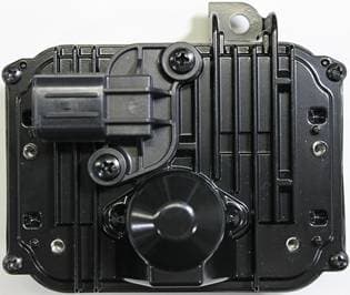
Click to zoom
Application Details
- Equipment Class
- FDS - Part 15 Field Disturbance Sensor
- Date of Grant
- Jun 26, 2014
- Application Purpose
- Original Equipment
- Date of Application
- Jun 26, 2014
- Equipment Note
- Millimeter Wave Radar Sensor
- Frequency Range
- 76500.00000000 - 76500.00000000
- Company
- Denso Corporation
- Country
- Japan
Documents & Files
Document Text
Text extracted from the exhibit documents filed with the FCC. Open a document above to read the original.
Users Manual
Manual Requirement of FCC / IC Our product (DNMWR008) is one of vehicle parts. Therefore, we will not supply the user’s manual. However, we will ask the vehicle manufacturer to include following statements in the vehicle user’s manual and service manual in accordance with FCC and IC requirements. 1. Requirement for User Manual 1.1. FCC Requirement In accordance with 15.21 of FCC rule, following statement will be included in the user’s manual. FCC WARNING Changes or modifications not expressly approved by the party responsible for compliance could void the user’s authority to operate the equipment. In accordance with requirement of FCC RF exposure, following statement will be included in the user’s manual. Radiofrequency radiation exposure Information: This equipment complies with FCC radiation exposure limits set forth for an uncontrolled environment. This equipment should be installed and operated with minimum distance of 20 cm between the radiator (antenna) and your body. This transmitter must not be co-located or operating in conjunction with any other antenna or transmitter. In accordance with requirement of FCC§15.19(a)(3), following statement will be included in the user’s manual. This device complies with part 15 of the FCC Rules. Operation is subject to the following two conditions: (1) This device may not cause harmful interference, and (2) this device must accept any interference received, including interference that may cause undesired operation. 1.2. IC Requirement In accordance with requirement of RSS-Gen, following statement will be included in the user’s manual. This device complies with Industry Canada licence-exempt RSS standard(s). Operation is subject to the following two conditions: (1) this device may not cause interference, and (2) this device must accept any interference, including interference that may cause undesired operation of the device. In accordance with requirement of RSS-102 of the IC radio frequency Exposure rules, following statement will be included in the user manual of the vehicle. This equipment complies with IC radiation exposure limits set forth for an uncontrolled environment and meets RSS-102 of the IC radio frequency (RF) Exposure rules. This equipment should be installed and operated keeping the radiator at least 20 cm or more away from person’s body. 2. Service manual In accordance with SAR requirement of FCC rule, following statement will be included in the service manual. Radiofrequency radiation exposure Information: This equipment complies with FCC radiation exposure limits set forth for an uncontrolled environment. This equipment should be kept with minimum distance of 20 cm between the radiator (antenna) and your body at all times during adjustment. This transmitter must not be co-located or operating in conjunction with any other antenna or transmitter.
Cover Letter(s)
1-1, Showa-cho, Kariya-shi, Aichi-ken, 448-8661, Japan Tel : +81-566-25-5947 Fax : +81-566-25-4548 Letter Of Agency June 3, 2014 UL Japan, Inc. 4383-326 Asama-cho, Ise-shi, Mie 516-0021 Japan FCC ID: HYQDNMWR008 To Whom It May Concern: Please be advised DENSO CORPORATION authorizes Yoshinobu Asai of Application Section, WiSE Japan, UL Verification Service, UL Japan, Inc. to act on our behalf, until otherwise notified, for applications submitted for Federal Communication Commission Radio equipment applications submitted to UL Japan, Inc. We certify that we are not subject to denial of federal benefits, that includes FCC benefits, pursuant to Section 5301 of the Anti-Drug Abuse ACT of 1988, U.S.C. 862. Further, no party, as defined in 47 CFR 1.2002(b), to the application is subject to denial of federal benefits, that includes FCC benefits. The application for the subject equipment has not been submitted to another TCB for certification. Thank you for your attention to this matter. Sincerely, Keiji Nagura General Manager Engineering Development Promotion Div. DENSO CORPORATION
Cover Letter(s)
1-1, Showa-cho, Kariya-shi, Aichi-ken, 448-8661, Japan Tel : +81-566-25-5947 Fax : +81-566-25-4548 Request for Confidentiality June 3, 2014 UL Japan, Inc. 4383-326 Asama-cho, Ise-shi, Mie 516-0021 Japan RE: Certification Application FCC ID: HYQDNMWR008 Please be advised that the following information is to be held confidential on behalf of DENSO CORPORATION, referring to the FCC rules 0.457 and 0.459: Schematic Diagram Block Diagram Parts List Theory of Operation The application contains technical information which DENSO CORPORATION deems to be trade secrets and proprietary. If made public, the information might be used to the disadvantage of the applicant in the market place. Thank you for your attention to this matter. Sincerely, Keiji Nagura General Manager Engineering Development Promotion Div. DENSO CORPORATION
External Photos
External photos (Model: DNMWR008) 1/6 External photos (Model: DNMWR008) 2/6 External photos (Model: DNMWR008) 3/6 External photos (Model: DNMWR008) 4/6 External photos (Model: DNMWR008) 5/6 External photos (Model: DNMWR008) 6/6
ID Label/Location Info
Marking layout and location (Model: DNMWR008) Fig. Marking Layout Fig. Marking Location (85.0) Marking location (12.0) Unit: mm Note: Marking layout, size and other indications maybe changed. Due to design constrains*, the space available for marking is limited to the position as illustrated above. * The radio wave is emitted from the front surface. Existence of any object on the surface may affect equipment’s RF performance, and no labels can be attached. Heat release fins are made on the back side, and there is no flat surface to attach labels.
Internal Photos
Internal photos (Model: DNMWR008) 1/6 Millimeter Wave Board Component side Antenna side Internal photos (Model: DNMWR008) 2/6 Power Supply Board Component side A Component side B Internal photos (Model: DNMWR008) 3/6 Internal photos (Model: DNMWR008) 4/6 Internal photos (Model: DNMWR008) 5/6 Internal photos (Model: DNMWR008) 6/6
RF Exposure Info
Test report No. : 10329820H-A-R1 Page : 1 of 2 Issued date : June 3, 2014 Revised date : June 23, 2014 FCC ID : HYQDNMWR008 UL Japan, Inc. Ise EMC Lab. 4383-326 Asama-cho, Ise-shi, Mie-ken 516-0021 JAPAN Telephone : +81 596 24 8999 Facsimile : +81 596 24 8124 Statement for RF Exposure Order No. : 10329820H-A-R1 Applicant : DENSO CORPORATION Type of Equipment : Millimeter Wave Radar Sensor Model No. : DNMWR008 Test standard : FCC Part 15 Subpart C: 2014 Test result : Complied [FCC rule] §1.1310 Radiofrequency radiation exposure limits. The criteria listed in table 1 shall be used to evaluate the environmental impact of human exposure to radiofrequency (RF) radiation as specified in §1.1307(b), except in the case of portable devices which shall be evaluated according to the provisions of §2.1093 of this chapter. Table 1—Limits for Maximum Permissible Exposure (MPE) Frequency range (MHz) Electric field strength (V/m) Magnetic field strength (A/m) Power density (mW/cm 2 ) Averaging time (minutes) (A) Limits for Occupational/Controlled Exposures 0.3–3.0 614 1.63 *(100) 6 3.0–30 1842/f 4.89/f *(900/f 2 ) 6 30–300 61.4 0.163 1.0 6 300–1500 f/300 6 1500–100,000 5 6 (B) Limits for General Population/Uncontrolled Exposure 0.3–1.34 614 1.63 *(100) 30 1.34–30 824/f 2.19/f *(180/f 2 ) 30 30–300 27.5 0.073 0.2 30 300–1500 f/1500 30 1500–100,000 1.0 30 f = frequency in MHz * = Plane-wave equivalent power density Note 1 to Table 1: Occupational/controlled limits apply in situations in which persons are exposed as a consequence of their employment provided those persons are fully aware of the potential for exposure and can exercise control over their exposure. Limits for occupational/controlled exposure also apply in situations when an individual is transient through a location where occupational/controlled limits apply provided he or she is made aware of the potential for exposure. Note 2 to Table 1: General population/uncontrolled exposures apply in situations in which the general public may be exposed, or in which persons that are exposed as a consequence of their employment may not be fully aware of the potential for exposure or can not exercise control over their exposure. Test report No. : 10329820H-A-R1 Page : 2 of 2 Issued date : June 3, 2014 Revised date : June 23, 2014 FCC ID : HYQDNMWR008 UL Japan, Inc. Ise EMC Lab. 4383-326 Asama-cho, Ise-shi, Mie-ken 516-0021 JAPAN Telephone : +81 596 24 8999 Facsimile : +81 596 24 8124 [Results] ModeDuty Factor [dBm][mW][dB][dBm][mW] Operating mode30.291070.1-2.3727.92619.6 Separation DistanceResultLimit [cm][mW/cm2][mW/cm2] 200.1231 Calculating formula: Average EIRP = Peak EIRP + Duty Factor Power Density = Average EIRP / (4 * Pi * Separation Distance ^ 2) Power Density Peak EIRPAverage EIRP (Peak with Duty Factor) These EIRP were measured in sufficient far field of 3m distance and calculated at 20cm.
Test Report
Test report No. : 10329820H-A-R2 Page : 2 of 23 Issued date : June 3, 2014 Revised date : June 26, 2014 FCC ID : HYQDNMWR008 UL Japan, Inc. Ise EMC Lab. 4383-326 Asama-cho, Ise-shi, Mie-ken 516-0021 JAPAN Telephone : +81 596 24 8999 Facsimile : +81 596 24 8124 REVISION HISTORY Original Test Report No.: 10329820H-A Revision Test report No. Date Page revised Contents - (Original) 10329820H-A June 3, 2014 - - 1 10329820H-A-R1 June 23, 2014 P. 4 Correction of Frequency of Operation 1 10329820H-A-R1 June 23, 2014 P. 5 Correction of tested voltage requirement 1 10329820H-A-R1 June 23, 2014 P. 10 Correction of measurement setting table 1 10329820H-A-R1 June 23, 2014 P. 11 Addition of measurement distance table 2 10329820H-A-R2 June 26, 2014 P. 11 Correction of Maximum Dimension Test report No. : 10329820H-A-R2 Page : 3 of 23 Issued date : June 3, 2014 Revised date : June 26, 2014 FCC ID : HYQDNMWR008 UL Japan, Inc. Ise EMC Lab. 4383-326 Asama-cho, Ise-shi, Mie-ken 516-0021 JAPAN Telephone : +81 596 24 8999 Facsimile : +81 596 24 8124 CONTENTS PAGE SECTION 1: Customer information ......................................................................................................... 4 SECTION 2: Equipment under test (E.U.T.) ........................................................................................... 4 SECTION 3: Test specification, procedures & results ............................................................................ 5 SECTION 4: Operation of E.U.T. during testing .................................................................................... 8 SECTION 5: Radiated Emission (Spurious Emission, Power Density) ............................................... 10 SECTION 6: Frequency Stability ........................................................................................................... 12 APPENDIX 1: Data of EMI test .............................................................................................................. 13 26dB and 99% Bandwidth ................................................................................................................ 13 Power Density ................................................................................................................................... 14 Spurious Emission ............................................................................................................................. 16 Frequency Stability ........................................................................................................................... 18 APPENDIX 2: Test instruments ............................................................................................................. 19 APPENDIX 3: Photographs of test setup ............................................................................................... 21 Spurious Emission ............................................................................................................................. 21 Carrier Frequency Measurement ....................................................................................................... 22 Frequency Stability ........................................................................................................................... 23 Test report No. : 10329820H-A-R2 Page : 4 of 23 Issued date : June 3, 2014 Revised date : June 26, 2014 FCC ID : HYQDNMWR008 UL Japan, Inc. Ise EMC Lab. 4383-326 Asama-cho, Ise-shi, Mie-ken 516-0021 JAPAN Telephone : +81 596 24 8999 Facsimile : +81 596 24 8124 SECTION 1: Customer information Company Name : DENSO CORPORATION Address : 1-1, Showa-cho, Kariya-shi, Aichi-ken, 448-8661 Japan Telephone Number : +81-566-61-3590 Facsimile Number : +81-566-25-4683 Contact Person : Takashi Sakurai SECTION 2: Equipment under test (E.U.T.) 2.1 Identification of E.U.T. Type of Equipment : Millimeter Wave Radar Sensor Model No. : DNMWR008 Serial No. : Refer to Section 4, Clause 4.2 Rating : DC 12V (Car battery), DC10V to 16V(Operating range) Receipt Date of Sample : May 10, 2014 Country of Mass-production : Japan Condition of EUT : Engineering prototype (Not for Sale: This sample is equivalent to mass-produced items.) Modification of EUT : No Modification by the test lab 2.2 Product Description This radar sensor (DNMWR008) is the 76GHz - 77GHz vehicle-mounted field disturbance sensor that is a millimeter wave frequency modulated continuous wave (FM-CW) radar operating at 76.0GHz to 77.0GHz (Nominal: 76.5GHz). General Specification Clock frequency(ies) in the system : Microcomputer: 10MHz Radio Specification Radio Type : Transceiver Frequency of Operation : 76.5GHz Modulation : FM-CW Antenna Type : Internal Antenna Antenna Connector : None Antenna Gain : 21.1dBi Antenna beam width (-3dB) : +/-10deg. (Horizontal), +/-2.5deg. (Vertical) Steerable Antenna : Electronically (Receiving Part only) Usage location : Forward-looking, vehicle-mounted Power Supply (inner) : DC -4.5V, DC6.5V Test report No. : 10329820H-A-R2 Page : 5 of 23 Issued date : June 3, 2014 Revised date : June 26, 2014 FCC ID : HYQDNMWR008 UL Japan, Inc. Ise EMC Lab. 4383-326 Asama-cho, Ise-shi, Mie-ken 516-0021 JAPAN Telephone : +81 596 24 8999 Facsimile : +81 596 24 8124 SECTION 3: Test specification, procedures & results 3.1 Test Specification Test Specification : FCC Part 15 Subpart C: 2014, final revised on May 1, 2014 and effective June 2, 2014 Title : FCC 47CFR Part15 Radio Frequency Device Subpart C Intentional Radiators Section 15.253 Operation within the bands 46.7-46.9GHz and 76.0-77.0GHz. * The revision on May 1, 2014 does not affect the test specification applied to the EUT. 3.2 Procedures and results Item Test Procedure Specification Worst margin Results Remarks Conducted Emission FCC: ANSI C63.4:2003 7. AC power line Conducted Emission measurements FCC: Section 15.207 N/A N/A *1) IC: RSS-Gen 7.2.4 IC: RSS-Gen 7.2.4 26dB Bandwidth FCC: "MILLIMETER WAVE TEST PROCEDURES" FCC: Section 15.253(f) See data. C…
Text truncated - open the document above for the full version.
Test Setup Photos
Test report No. : 10329820H-A-R2 Page : 21 of 23 Issued date : June 3, 2014 Revised date : June 26, 2014 FCC ID : HYQDNMWR008 UL Japan, Inc. Ise EMC Lab. 4383-326 Asama-cho, Ise-shi, Mie-ken 516-0021 JAPAN Telephone : +81 596 24 8999 Facsimile : +81 596 24 8124 APPENDIX 3: Photographs of test setup Spurious Emission Photo 1 Photo 2 Test report No. : 10329820H-A-R2 Page : 22 of 23 Issued date : June 3, 2014 Revised date : June 26, 2014 FCC ID : HYQDNMWR008 UL Japan, Inc. Ise EMC Lab. 4383-326 Asama-cho, Ise-shi, Mie-ken 516-0021 JAPAN Telephone : +81 596 24 8999 Facsimile : +81 596 24 8124 Carrier Frequency Measurement Photo 1 Photo 2 Test report No. : 10329820H-A-R2 Page : 23 of 23 Issued date : June 3, 2014 Revised date : June 26, 2014 FCC ID : HYQDNMWR008 UL Japan, Inc. Ise EMC Lab. 4383-326 Asama-cho, Ise-shi, Mie-ken 516-0021 JAPAN Telephone : +81 596 24 8999 Facsimile : +81 596 24 8124 Frequency Stability Photo 1 Photo 2 End of Report
Contact Information
Applicant
Keijiro Kumagai(Manager)
Technical Contact
UL Japan, Inc.Takayuki Shimada
[email protected]@ul.com81-596-24-8999
4383-326 Asama-cho, Ise-shi · Mie-ken · Japan
Test Firm
UL Japan, Inc. Head office EMC Lab.Tetsuya Hashimoto
Technical Specifications
| # | Rule Parts | Frequency Range | Power Output |
|---|---|---|---|
| 1 | 15.253 | 76.50 GHz - 76.50 GHz | - |
Other Applications from Denso Corporation
HYQDNILR001
Aug 04, 2026LiDsEYE
Equipment Class
JAB - Part 15 Class B Digital DeviceHYQDNMWR020
Mar 27, 2026Millimeter Wave Radar Sensor
Equipment Class
VRD - Part 95 Vehicular Radar SystemsHYQDNMWR021
Mar 10, 2026Millimeter Wave Radar Sensor
Equipment Class
VRD - Part 95 Vehicular Radar SystemsHYQ23ABR
Mar 05, 2026Remote Keyless Entry System and TPMS (Receiver)
Equipment Class
CYY - Communications Receiver used w/Pt 15 TransmitterHYQDNMWR018RAM
Oct 10, 2024Millimeter Wave Radar Sensor
Equipment Class
VRD - Part 95 Vehicular Radar Systems