HYQUPE01Passive Entry Passive Start System (LF Transmitter)
Denso Corporation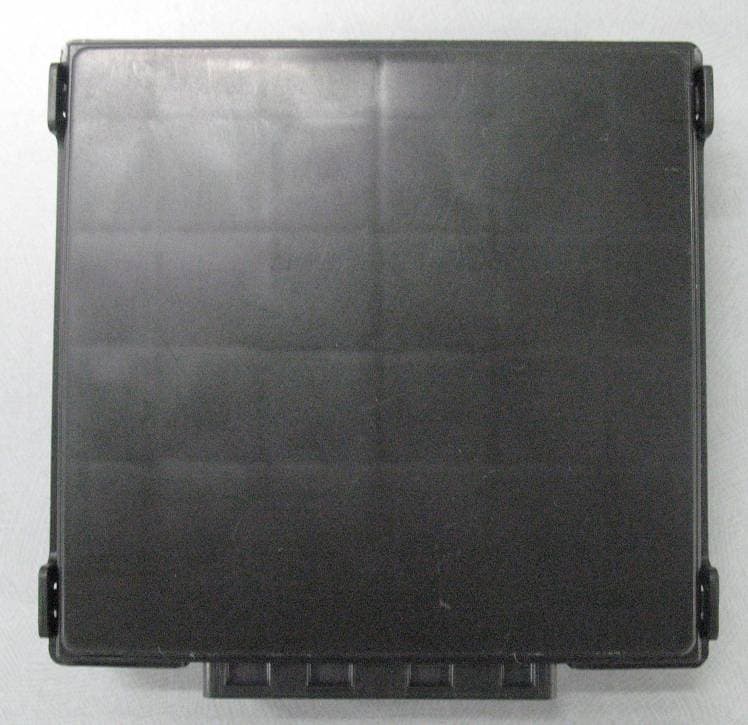
Click to zoom
Application Details
- Equipment Class
- DCD - Part 15 Low Power Transmitter Below 1705 kHz
- Date of Grant
- Nov 29, 2012
- Application Purpose
- Original Equipment
- Date of Application
- Nov 28, 2012
- Equipment Note
- Passive Entry Passive Start System (LF Transmitter)
- Frequency Range
- 0.12500000 - 0.12500000
- Company
- Denso Corporation
- Country
- Japan
Documents & Files
Document Text
Text extracted from the exhibit documents filed with the FCC. Open a document above to read the original.
Users Manual
Manual Requirement of FCC / IC Our product (UPE01) is one of vehicle parts. Therefore, we will not supply the user’s manual. However, we will ask the vehicle manufacturer to include following statements in the vehicle user’s manual in accordance with FCC and IC requirements. 1. Requirement for User Manual 1.1. FCC Requirement 1.1.1. In accordance with 15.21 of FCC rule, following statement will be included in the user’s manual. 1.1.2. In accordance with requirement of FCC§15.19(a)(5), following statement will be included in the user’s manual. 1.2. IC Requirement 1.2.1. In accordance with requirement of RSS-GEN, following statement will be included in the user’s manual. FCC WARNING Changes or modifications not expressly approved by the party responsible for compliance could void the user’s authority to operate the equipment. NOTE This device complies with part 15 of the FCC Rules. Operation is subject to the following two conditions: (1) This device may not cause harmful interference, and (2) this device must accept any interference received, including interference that may cause undesired operation. NOTE This device complies with Industry Canada licence-exempt RSS standard(s). Operation is subject to the following two conditions: (1) this device may not cause interference, and (2) this device must accept any interference, including interference that may cause undesired operation of the device.
Cover Letter(s)
1-1, Showa-cho, Kariya-shi, Aichi-ken, 448-8661, Japan Tel : +81-566-25-5947 Fax : +81-566-25-4548 Letter Of Agency Date: November 30, 2012 Compliance Certification Services Certification Division 47173 Benicia Street Fremont, CA 94538, USA FCC ID: HYQUPE01 To Whom It May Concern: Please be advised DENSO CORPORATION authorizes Yoshinobu Asai of Application Section, WiSE Japan, UL Verification Service, UL Japan, Inc. to act on our behalf, until otherwise notified, for applications submitted for Federal Communication Commission Radio equipment applications submitted to UL Japan, Inc. We certify that we are not subject to denial of federal benefits, that includes FCC benefits, pursuant to Section 5301 of the Anti-Drug Abuse ACT of 1988, U.S.C. 862. Further, no party, as defined in 47 CFR 1.2002(b), to the application is subject to denial of federal benefits, that includes FCC benefits. The application for the subject equipment has not been submitted to another TCB for certification. Thank you for your attention to this matter. Sincerely, Kazuo Sakakibara General Manager DENSO CORPORATION
Cover Letter(s)
1-1, Showa-cho, Kariya-shi, Aichi-ken, 448-8661, Japan Tel : +81-566-25-5947 Fax : +81-566-25-4548 Request for Confidentiality Date: November 30, 2012 Compliance Certification Services Certification Division 47173 Benicia Street Fremont, CA 94538, USA RE: Certification Application FCC ID: HYQUPE01 Please be advised that the following information is to be held confidential on behalf of DENSO CORPORATION, referring to the FCC rules 0.457 and 0.459: Schematic Diagram Block Diagram Parts List Theory of Operation The application contains technical information which DENSO CORPORATION deems to be trade secrets and proprietary. If made public, the information might be used to the disadvantage of the applicant in the market place. Thank you for your attention to this matter. Sincerely, Kazuo Sakakibara General Manager DENSO CORPORATION
External Photos
DENSO CORPORATION Passive Entry Passive Start System (LF Transmitter) FCC ID: HYQUPE01 IC Number: 1551A-UPE01 External Photos (UPE) 1/3 Front Rear NOTE Other indications may be added. DENSO CORPORATION Passive Entry Passive Start System (LF Transmitter) FCC ID: HYQUPE01 IC Number: 1551A-UPE01 External Photos (UPE) 2/3 Top Bottom DENSO CORPORATION Passive Entry Passive Start System (LF Transmitter) FCC ID: HYQUPE01 IC Number: 1551A-UPE01 External Photos (UPE) 3/3 Right Left DENSO CORPORATION Passive Entry Passive Start System (LF Transmitter) FCC ID: HYQUPE01 IC Number: 1551A-UPE01 External Photos (ANTENNA) 1/2 Front Rear DENSO CORPORATION Passive Entry Passive Start System (LF Transmitter) FCC ID: HYQUPE01 IC Number: 1551A-UPE01 External Photos (ANTENNA) 2/2 Top Bottom Right Left
ID Label/Location Info
10. Marking location and layout Fig. Marking location and layout of UPE Note: Compliance statement of marking will not be changed. But making layout, size and other indications maybe changed. Unit: mm 12
Internal Photos
DENSO CORPORATION Passive Entry Passive Start System (LF Transmitter) FCC ID: HYQUPE01 IC Number: 1551A-UPE01 Internal Photos (UPE) Component Side Solder Side DENSO CORPORATION Passive Entry Passive Start System (LF Transmitter) FCC ID: HYQUPE01 IC Number: 1551A-UPE01 Internal Photos (ANTENNA)
Test Report
Test report No. : 32JE0268-HO-02-A-R2 Page : 2 of 30 Issued date : November 1, 2012 Revised date : November 26, 2012 FCC ID : HYQUPE01 UL Japan, Inc. Head Office EMC Lab. 4383-326 Asama-cho, Ise-shi, Mie-ken 516-0021 JAPAN Telephone : +81 596 24 8116 Facsimile : +81 596 24 8124 CONTENTS PAGE SECTION 1: Customer information ..................................................................................................... 3 SECTION 2: Equipment under test (E.U.T.) ........................................................................................ 3 SECTION 3: Test specification, procedures & results ........................................................................ 4 SECTION 4: Operation of E.U.T. during testing ................................................................................. 7 SECTION 5: Radiated emission (Fundamental and Spurious Emission) .......................................... 8 SECTION 6: -26dB Bandwidth ............................................................................................................ 10 SECTION 7: 99% Occupied Bandwidth ............................................................................................. 10 APPENDIX 1: Data of EMI test ........................................................................................................... 11 Radiated Emission below 30MHz (Fundamental and Spurious Emission) ................................. 11 Duty Cycle(Total calculation) .......................................................................................................... 21 Duty Cycle(Ant1 ON time) ............................................................................................................... 21 Duty Cycle(Ant4 ON time) ............................................................................................................... 25 -26dB Bandwidth ............................................................................................................................... 26 99% Occupied Bandwidth ................................................................................................................ 27 APPENDIX 2: Test instruments .......................................................................................................... 28 APPENDIX 3: Photographs of test setup ............................................................................................ 29 Radiated Emission ............................................................................................................................. 29 Worst Case Position (EUT: X-axis / Antenna: X-axis) .................................................................. 30 Test report No. : 32JE0268-HO-02-A-R2 Page : 3 of 30 Issued date : November 1, 2012 Revised date : November 26, 2012 FCC ID : HYQUPE01 UL Japan, Inc. Head Office EMC Lab. 4383-326 Asama-cho, Ise-shi, Mie-ken 516-0021 JAPAN Telephone : +81 596 24 8116 Facsimile : +81 596 24 8124 SECTION 1: Customer information Company Name : DENSO CORPORATION Address : 1-1 Showa-cho, Kariya-shi, Aichi-ken, 448-8661 Japan Telephone Number : +81-566-61-2507 Facsimile Number : +81-566-25-4837 Contact Person : TOSHIO SHIMOMURA SECTION 2: Equipment under test (E.U.T.) 2.1 Identification of E.U.T. Type of Equipment : Passive Entry Passive Start System (LF Transmitter) Model No. : UPE01 Serial No. : Refer to Section 4, Clause 4.2 Receipt Date of Sample : June 7, 2012 Country of Mass-production : United states of America and China Condition of EUT : Production prototype (Not for Sale: This sample is equivalent to mass-produced items.) Modification of EUT : No Modification by the test lab 2.2 Product Description General Specification Clock frequency(ies) in the system : MPU: 4MHz Radio Specification Radio Type : LF Transmitter Frequency of Operation : 125kHz Oscillation circuit : Ceramic resonator Oscillator frequency : 8MHz Resonator Modulation : OOK Power Supply (inner) : DC 12.0V Antenna port type : Port type1: Ant 1, 2, 6 (Not inserted resistance between LF Drive Circuit and Output Port in series) Port type2: Ant 3, 4, 5 (Inserted resistance between LF Drive Circuit and Output Port in series) Antenna specification : Ferrite antenna coil (impedance 2Ω - 54Ω)[End user cannot control impedance since it is fixed depending on each system] Transmitting out put current : 50mA - 1000mA [End user cannot control output current since it is fixed depending on each system] This system has ports three Port type1 and three Port type2. These 6 ports do not transmit simultaneously. The application document indicats a relationship between transmitting output current and output field strength by the difference in an antenna impedance. Test report No. : 32JE0268-HO-02-A-R2 Page : 4 of 30 Issued date : November 1, 2012 Revised date : November 26, 2012 FCC ID : HYQUPE01 UL Japan, Inc. Head Office EMC Lab. 4383-326 Asama-cho, Ise-shi, Mie-ken 516-0021 JAPAN Telephone : +81 596 24 8116 Facsimile : +81 596 24 8124 SECTION 3: Test specification, procedures & results 3.1 Test Specification Test Specification : FCC Part 15 Subpart C: 2012, final revised on August 13, 2012 and effective September 12, 2012 Title : FCC 47CFR Part15 Radio Frequency Device Subpart C Intentional Radiators Section 15.207 Conducted Emission Section 15.209 Radiated emission limits, general requirements * The revision on August 13, 2012 does not affect the test specification applied to the EUT. FCC 15.31 (e) The EUT is a battery-operated device and test was performed with the full-charged battery. Therefore, this EUT complies with the requirement. FCC Part 15.203 Antenna requirement It is impossible for end users to replace the antenna, because the antenna is mounted inside of the vehicle. Therefore, the equipment complies with the antenna requirement of Section 15.203. 3.2 Procedures and results No. Item Test Procedure Specification RemarksDeviation Worst margin Results 1 Conducted Emission <FCC> ANSI C63.4:2003 7. AC powerlin…
Text truncated - open the document above for the full version.
Test Setup Photos
Test report No. : 32JE0268-HO-02-A-R2 Page : 29 of 30 Issued date : November 1, 2012 Revised date : November 26, 2012 FCC ID : HYQUPE01 UL Japan, Inc. Head Office EMC Lab. 4383-326 Asama-cho, Ise-shi, Mie-ken 516-0021 JAPAN Telephone : +81 596 24 8116 Facsimile : +81 596 24 8124 APPENDIX 3: Photographs of test setup Radiated Emission Photo 1 Photo 2 Test report No. : 32JE0268-HO-02-A-R2 Page : 30 of 30 Issued date : November 1, 2012 Revised date : November 26, 2012 FCC ID : HYQUPE01 UL Japan, Inc. Head Office EMC Lab. 4383-326 Asama-cho, Ise-shi, Mie-ken 516-0021 JAPAN Telephone : +81 596 24 8116 Facsimile : +81 596 24 8124 Worst Case Position (EUT: X-axis / Antenna: X-axis) UPE Ant X-axis X-axis Y-axis Y-axis Z-axis Z-axis End of Report
Contact Information
Applicant
Keijiro Kumagai(Manager)
Technical Contact
UL Japan, Inc.Shinya Watanabe
[email protected]81-596-24-8116
4383-326 Asama-cho, Ise-shi · Mie-ken · Japan
Test Firm
UL Japan, Inc. Head office EMC Lab.Tetsuya Hashimoto
Technical Specifications
| # | Rule Parts | Frequency Range | Power Output |
|---|---|---|---|
| 1 | 15C | 0.125 MHz - 0.125 MHz | - |
Other Applications from Denso Corporation
HYQDNILR001
Aug 04, 2026LiDsEYE
Equipment Class
JAB - Part 15 Class B Digital DeviceHYQDNMWR020
Mar 27, 2026Millimeter Wave Radar Sensor
Equipment Class
VRD - Part 95 Vehicular Radar SystemsHYQDNMWR021
Mar 10, 2026Millimeter Wave Radar Sensor
Equipment Class
VRD - Part 95 Vehicular Radar SystemsHYQ23ABR
Mar 05, 2026Remote Keyless Entry System and TPMS (Receiver)
Equipment Class
CYY - Communications Receiver used w/Pt 15 TransmitterHYQDNMWR018RAM
Oct 10, 2024Millimeter Wave Radar Sensor
Equipment Class
VRD - Part 95 Vehicular Radar Systems