HZB-4954RSingle Band Wireless AP W/ Build in Amplifiers
Proxim Wireless Corporation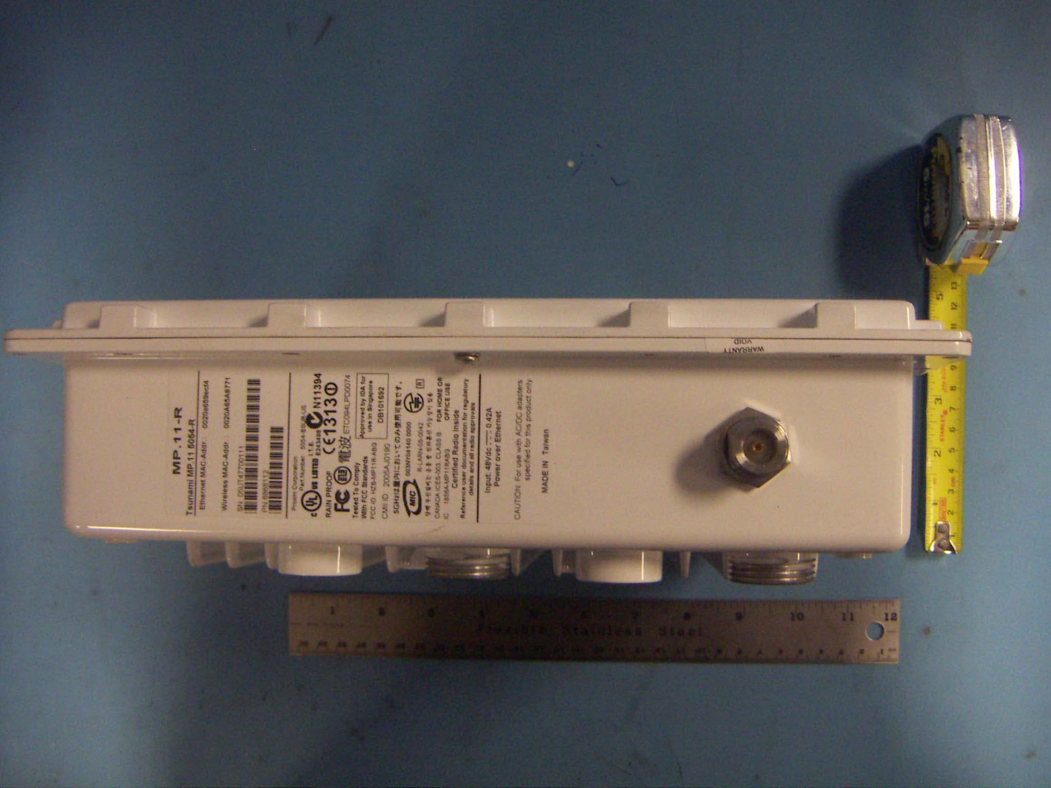
Click to zoom
Application Details
- Equipment Class
- TNB - Licensed Non-Broadcast Station Transmitter
- Date of Grant
- Dec 20, 2006
- Application Purpose
- Original Equipment
- Date of Application
- Dec 20, 2006
- Equipment Note
- Single Band Wireless AP W/ Build in Amplifiers
- Frequency Range
- 4950.00000000 - 4980.00000000
- Company
- Proxim Wireless Corporation
- Country
- United States
Documents & Files
Document Text
Text extracted from the exhibit documents filed with the FCC. Open a document above to read the original.
Users Manual
Tsunami MP.11 Model 4954-R Installation and Management MP.11 4954-R Installation and Management 2 Copyright ©2006 Proxim Wireless Corporation, San Jose, CA. All rights reserved. Covered by one or more of the following U.S. patents: 5,231,634; 5,875,179; 6,006,090; 5,809,060; 6,075,812; 5,077,753. This manual and the software described herein are copyrighted with all rights reserved. No part of this publication may be reproduced, transmitted, transcribed, stored in a retrieval system, or translated into any language in any form by any means without the written permission of Proxim Wireless Corporation. Trademarks Tsunami, Proxim, and the Proxim logo are trademarks of Proxim Wireless Corporation. All other trademarks mentioned herein are the property of their respective owners. Tsunami MP.11 4954-R Installation and Management Guide P/N 73328 November 2006 IMPORTANT! Before installing and using this product, see the Safety and Regulatory Compliance Guide located on the product CD. MP.11 4954-R Installation and Management 1 Contents 1 Introduction . . . . . . . . . . . . . . . . . . . . . . . . . . . . . . . . . . . . . . . . . . . . . . . . . . . . . . . . . . . . . . . . . . 9 About This Book . . . . . . . . . . . . . . . . . . . . . . . . . . . . . . . . . . . . . . . . . . . . . . . . . . . . . . . . . . . . . . . . . . . . . . 9 Reference Manual . . . . . . . . . . . . . . . . . . . . . . . . . . . . . . . . . . . . . . . . . . . . . . . . . . . . . . . . . . . . . . . . . . . . . . . . . 10 Wireless Network Topologies . . . . . . . . . . . . . . . . . . . . . . . . . . . . . . . . . . . . . . . . . . . . . . . . . . . . . . . . . . . 11 Point-to-Point Link . . . . . . . . . . . . . . . . . . . . . . . . . . . . . . . . . . . . . . . . . . . . . . . . . . . . . . . . . . . . . . . . . . . . . . . . . 11 Point-to-Multipoint Network . . . . . . . . . . . . . . . . . . . . . . . . . . . . . . . . . . . . . . . . . . . . . . . . . . . . . . . . . . . . . . . . . . 11 Management and Monitoring Capabilities . . . . . . . . . . . . . . . . . . . . . . . . . . . . . . . . . . . . . . . . . . . . . . . . . 12 Web Interface . . . . . . . . . . . . . . . . . . . . . . . . . . . . . . . . . . . . . . . . . . . . . . . . . . . . . . . . . . . . . . . . . . . . . . . . . . . . . 12 Command Line Interface . . . . . . . . . . . . . . . . . . . . . . . . . . . . . . . . . . . . . . . . . . . . . . . . . . . . . . . . . . . . . . . . . . . . 12 SNMP Management . . . . . . . . . . . . . . . . . . . . . . . . . . . . . . . . . . . . . . . . . . . . . . . . . . . . . . . . . . . . . . . . . . . . . . . . 12 2 Installation and Initialization . . . . . . . . . . . . . . . . . . . . . . . . . . . . . . . . . . . . . . . . . . . . . . . . . . . 14 Hardware Overview . . . . . . . . . . . . . . . . . . . . . . . . . . . . . . . . . . . . . . . . . . . . . . . . . . . . . . . . . . . . . . . . . . 15 Power-over-Ethernet . . . . . . . . . . . . . . . . . . . . . . . . . . . . . . . . . . . . . . . . . . . . . . . . . . . . . . . . . . . . . . . . . . . . . . . 15 Serial Connection . . . . . . . . . . . . . . . . . . . . . . . . . . . . . . . . . . . . . . . . . . . . . . . . . . . . . . . . . . . . . . . . . . . . . . . . . . 15 External Antenna Connection. . . . . . . . . . . . . . . . . . . . . . . . . . . . . . . . . . . . . . . . . . . . . . . . . . . . . . . . . . . . . . . . . 16 Product Package . . . . . . . . . . . . . . . . . . . . . . . . . . . . . . . . . . . . . . . . . . . . . . . . . . . . . . . . . . . . . . . . . . . . 17 Hardware Installation . . . . . . . . . . . . . . . . . . . . . . . . . . . . . . . . . . . . . . . . . . . . . . . . . . . . . . . . . . . . . . . . . 19 Step 1: Choose a Location . . . . . . . . . . . . . . . . . . . . . . . . . . . . . . . . . . . . . . . . . . . . . . . . . . . . . . . . . . . . . . . . . . . 20 Step 2: Unpack Shipping Box . . . . . . . . . . . . . . . . . . . . . . . . . . . . . . . . . . . . . . . . . . . . . . . . . . . . . . . . . . . . . . . . . 21 Step 3: Assemble the Cable . . . . . . . . . . . . . . . . . . . . . . . . . . . . . . . . . . . . . . . . . . . . . . . . . . . . . . . . . . . . . . . . . . 22 Step 4: Determine Proper Mounting Orientation. . . . . . . . . . . . . . . . . . . . . . . . . . . . . . . . . . . . . . . . . . . . . . . . . . . 23 Step 5: Assemble Mounting Hardware . . . . . . . . . . . . . . . . . . . . . . . . . . . . . . . . . . . . . . . . . . . . . . . . . . . . . . . . . . 24 Step 6: Mount the Unit . . . . . . . . . . . . . . . . . . . . . . . . . . . . . . . . . . . . . . . . . . . . . . . . . . . . . . . . . . . . . . . . . . . . . . 25 Step 7: Plug in the Cables . . . . . . . . . . . . . . . . . . . . . . . . . . . . . . . . . . . . . . . . . . . . . . . . . . . . . . . . . . . . . . . . . . . 26 Step 8: Power on the Unit. . . . . . . . . . . . . . . . . . . . . . . . . . . . . . . . . . . . . . . . . . . . . . . . . . . . . . . . . . . . . . . . . . . . 27 Step 9: View LEDs . . . . . . . . . . . . . . . . . . . . . . . . . . . . . . . . . . . . . . . . . . . . . . . . . . . . . . . . . . . . . . . . . . . . . . . . . 27 Step 10: Align the Antenna . . . . . . . . . . . . . . . . . . . . . . . . . . . . . . . . . . . . . . . . . . . . . . . . . . . . . . . . . . . . . . . . . . . 28 Antenna Alignment Commands. . . . . . . . . . . . . . . . . . . . . . . . . . . . . . . . . . . . . . . . . . . . . . . . . . . . . . . . . . . . . 29 Step 11: Tighten the Cables . . . . . . . . . . . . . . . . . . . . . . . . . . . . . . . . . . . . . . . . . . . . . . . . . . . . . . . . . . . . . . . . . . 30 Step 12: Weatherproof the Connectors . . . . . . . . . . . . . . . . . . . . . . . . . . . . . . . . . . . . . . . . . . . . . . . . . . . . . . . . . 31 Step 13: Install Documentation and Software. . . . . . . . . . . . . . . . . . . . . . . . . . . . . . . . . . . . . . . . . . . . . . . . . . . . . 32 Initialization . . . . . . . . . .…
Text truncated - open the document above for the full version.
Users Manual
ConfigurationMP.11 4954-R Installation and Management Intra-Cell Blocking (Base Station Unit Only) 99 Enter the MAC address of the SU. Select Enable from the drop-down menu for the Group Index Click Add. The MAC address is assigned to the groups. Additions to the MAC Table take effect immediately after clicking the Add button. You can Enable, Disable, Delete, or Reassign the groups for a MAC address by using the Edit/Delete Table Entries button. A maximum of 250 MAC addresses can be added among all filter groups. Block Traffic Between SUs (Security Gateway) You can configure a Security Gateway to block traffic between SUs connected to different BSUs. Verify that Intra-Cell Blocking has been enabled on the Group Table tab before configuring the Security Gateway. •Security Gateway Status: Enables or disables packet forwarding to the external Security Gateway. •Security Gateway MAC Address: Lets you configure the MAC address of the external Security Gateway. ConfigurationMP.11 4954-R Installation and Management VLAN Parameters 100 VLAN Parameters Virtual LAN (VLAN) implementation in the Tsunami products: • Lets the BSU and SU be used in a VLAN-aware network. • Processes IEEE 802.1Q VLAN-tagged packets. Network resources behind the BSU and SU can be assigned to logical groups. Overview VLAN Modes Transparent Mode Transparent mode is available on both the SU and the BSU. This mode is equivalent to NO VLAN support and is the default mode. It is used when the devices behind the SU and BSU are both VLAN aware and unaware. The SU/BSU transfers both tagged and untagged frames received on the Ethernet or WORP interface. Both tagged and untagged management frames can access the device. Trunk Mode Trunk mode VLAN is available on both the SU and the BSU. It is used when all devices behind the SU and BSU are VLAN aware. The SU and BSU transfer only tagged frames received on the Ethernet or WORP interface. Both tagged and untagged management frames can access the device. Access Mode Access mode is available only on the SU. It is used when the devices behind the SU are VLAN unaware. Frames to and from the Ethernet interface behind the SU map into only one VLAN segment. Frames received on the Ethernet interface are tagged with the configured Access VLAN ID before forwarding them to the WORP interface. Both tagged and untagged management frames can access the device from the WORP interface. However, only untagged management frames can access the device from the Ethernet Interface. VLAN Forwarding The VLAN Trunk mode provides a means to configure a list of VLAN IDs in a Trunk VLAN Table. The SU and BSU only forward frames (between Ethernet and WORP interface) tagged with the VLAN IDs configured in the Trunk VLAN Table. Up to 256 VLAN IDs can be configured for the BSU and up to 16 VLAN IDs can be configured for the SU (depending upon the capabilities of your switching equipment). VLAN Relaying The VLAN Trunk mode for BSU operation provides an option to enable and disable a VLAN relaying flag; when enabled, the BSU shall relay frames between SUs on the same BSU having the same VLAN ID. Management VLAN The BSU and SU allow the configuration of a separate VLAN ID and priority for SNMP, ICMP, Telnet, and TFTP management frames for device access. The management VLAN ID and management VLAN priority may be applied in any mode. The management stations tag the management frames they send to the BSU or SU with the management VLAN ID configured in the device. The BSU and SU tag all the management frames from the device with the configured management VLAN and priority. ConfigurationMP.11 4954-R Installation and Management VLAN Parameters 101 BSU and SU in Transparent Mode When the BSU is in Transparent mode, all associated SUs must be in Transparent mode. How the BSU and SUs function in Transparent mode is described in the following table. BSU in Trunk Mode and SU in Trunk/Access Mode When the BSU is in Trunk mode, the associated SUs must be in either Trunk mode or Access mode. When an SU associates to a BSU that is in Trunk mode, it gets the VLAN mode from the BSU. How the BSU and SU function in Trunk mode, and the SU in Access mode, is described in the following table. BSU Function – Transparent ModeSU Function – Transparent Mode • BSU forwards both tagged and untagged frames received from the Ethernet interface or from any of the associated SUs. • If a valid management VLAN ID is configured, BSU allows only management frames tagged with the configured management VLAN ID to access it. • If a valid management VLAN ID is configured, BSU tags all management frames generated by the BSU with the configured management VLAN ID and priority. • If the management VLAN ID is configured as - 1 (untagged), BSU allows only untagged management frames to access it. • SU forwards both tagged and untagged frames received from the Ethernet interface or from the BSU. • If a valid management VLAN ID is configured, SU allows only management frames tagged with the configured management VLAN ID to access it. • If a valid management VLAN ID is configured, SU tags all management frames generated by the SU with the configured management VLAN ID and priority. • If the management VLAN ID is configured as - 1 (untagged), SU allows only untagged management frames to access them. ConfigurationMP.11 4954-R Installation and Management VLAN Parameters 102 BSU VLAN Configuration The HTTP Interface to configure BSU VLAN parameters is shown in the following figure. BSU Function – Trunk ModeSU Function – Trunk ModeSU Function – Access Mode • Up to 256 VLAN IDs can be configured on a BSU. • BSU discards all untagged frames received from the Ethernet interface or from any of the associated SUs (unexpected). • If a valid VLAN ID is configured, BSU forwards only VLAN-tagged frames received from the Ethernet interface or from any of the associated SUs that are tagged with the configured VLAN IDs; it discards all other tagged frames. • If a valid management VLAN…
Text truncated - open the document above for the full version.
Users Manual
Tsunami MP.11 Model 4954-R Safety and Regulatory Compliance Information (December 2006) IMPORTANT! Visit http://support.proxim.com for the latest safety and regulatory compliance information for this product. Tsunami MP.11 Model 4954-R Safety and Regulatory Information 2 Copyright © 2006 Proxim Corporation. All rights reserved. Covered by one or more of the following U.S. patents: 5,231,634; 5,875,179; 6,006,090; 5,809,060; 6,075,812; 5,077,753. This user’s guide and the software described in it are copyrighted with all rights reserved. No part of this publication may be reproduced, transmitted, transcribed, stored in a retrieval system, or translated into any language in any form by any means without the written permission of Proxim Corporation. Trademarks Tsunami, Proxim, and the Proxim logo are trademarks of Proxim Wireless Corporation. All other trademarks mentioned herein are the property of their respective owners. Tsunami Model 4954-R Safety and Regulatory Compliance Information P/N 73372 December 2006 Products Covered in the Guide Tsunami MP.11 Model 4954-R Safety and Regulatory Information 3 Products Covered in the Guide This document contains important safety and regulatory compliance information for the following products: Please see the following sections for more information: •Safety Information •FCC Compliance Information •Information for Professional Installers IMPORTANT! Visit http://support.proxim.com for the latest safety and regulatory compliance information for this product. Please read this document before installing and using your product, and save these instructions. ProductModel Numbers Tsunami MP.11 4954-R, Base Station Unit 4.9 GHz (US only) 4954-BSUR-US Tsunami MP.11 4954-R, Subscriber Unit 4.9 GHz (US only) 4954-SUA-US Tsunami MP.11 4954-R, Subscriber Unit 4.9 GHz, Antenna versions (US only) 4954-SUR-US Safety Information Tsunami MP.11 Model 4954-R Safety and Regulatory Information 4 Safety Information These products have been evaluated to, and comply with, the U.S. and Canadian (Bi National) Standard for Safety of Information Technology Equipment, including Electrical Business Equipment, CANCSA C22.2, No. 60950-00 * UL 60950 3 rd edition and IEC60950:1999, the Standard for the Safety of Information Technology Equipment. When using this device, basic safety precautions should always be followed to reduce the risk of fire, electrical shock, and injury to persons, including the following: • All products are intended to be installed, used, and maintained by experienced telecommunications personnel only. • These products have been evaluated for outdoor use. • Operate and install these products as described in this manual. Equipment must be installed and used in strict accordance with the manufacturer's instructions as described in the user documentation provided. • Installation of these products must conform to local regulations and codes. • Products are to be used with and powered by only the power injector provided. • A 15-amp circuit breaker is required at the power source. WARNING: This equipment is intended to be grounded. A 10 AWG earthing conductor at a minimum is to be used for this purpose. • The maximum room ambient temperature (Tmra) for these products is 55° C. Consideration should be given to installing this equipment in an environment compatible with the Tmra. • Do not connect or disconnect the power cable to the equipment when the power injector is plugged into an AC power outlet. • To avoid the risk of electric shock from lightning, do not use this product during an electrical storm. • When using this product with external antenna, see the installation documentation provided with the antenna system. • No user serviceable parts; all repairs and service must be handled by a qualified service center. • Do not remove or alter the Marking label provided on these products. FCC Compliance Information Tsunami MP.11 Model 4954-R Safety and Regulatory Information 5 FCC Compliance Information Operation in the 4.9 GHz band requires an FCC license. As specified in Part 90.1203 of the FCC rules, eligibility requirements are as follows: 1. Entities providing public safety services as defined under section 90.523 are eligible to hold a Commission license for systems operating in the 4940–4990 MHz band. All of the requirements and conditions set forth in that section also govern authorizations in the 4940–4990 MHz band. 2. 4.9 GHz band licensees may enter into sharing agreements or other arrangements for use of the spectrum with entities that do not meet these eligibility requirements. However, all applications in the band are limited to operations in support of public safety. To comply with the FCC radio frequency exposure requirements, the following antenna installation and device operating configurations must be satisfied: •Product models using external antennas require professional installation. • The antennas used for professional installation must be fixed-mounted on indoor/outdoor permanent structures with a separation distance of at least 100 cm from all persons. • Antennas must not be co-located and must not operate in conjunction with any other antenna or transmitter. Modifications Changes or modifications to this device that are not expressly approved by the manufacturer of the product could void the user’s authority to operate the equipment. Warnings This equipment has been tested and found to comply with the limits for a Class B digital device, pursuant to Part 15 of the FCC Rules. These limits are designed to provide reasonable protection against harmful interference in a residential installation. This equipment generates, uses, and can radiate radio frequency energy, and, if not installed and used in accordance with the instructions, may cause harmful interference to radio communications. However, there is no guarantee that interference will not occur in a particular installation. If this equipment does cause harmful interference to radio or televisi…
Text truncated - open the document above for the full version.
Cover Letter(s)
2115 O'Nel Drive, San Jose, CA 95131 P 408.731.2700 F 408.731.3675 www.proxim.com Date: October 4, 2006 Compliance Certification Services Certification Division 561F Monterey Road Morgan Hill, CA 95037 To whom it may concern: We, the undersigned, hereby authorize the Testing Division of Compliance Engineering Services, Inc., d.b.a. Compliance Certification Services and hereafter referred to as CCS, to act on our behalf in all manners relating to application for equipment authorization, including signing of all documents relating to these matters. Any and all acts carried out by CCS on our behalf shall have the same effect as acts of our own. We, the undersigned, hereby certify that we are not subject to a denial of federal benefits, that includes FCC benefits, pursuant to Section 5301 of the Anti-Drug Abuse Act of 1988, 21 U.S.C. 853(a). In authorizing CCS Testing Division as our agent, we still recognize that we are responsible to: a) comply with the relevant provisions of the certification program; b) make all necessary arrangements for the conduct of the evaluation, including provision for examining documentation and access to all areas, records (including internal audit reports) and personnel for the purposes of evaluation (e.g. testing, inspection, assessment, surveillance, reassessment) and resolution of complaints; c) make claims regarding certification only in respect of the scope for which certification has been granted; d) do not use our product certification in such a manner as to bring the Certification Division into disrepute and not make any statement regarding our product certification which the Certification Division may consider misleading or unauthorized; e) upon suspension or cancellation of certification, discontinue use of all advertising matter that contains any reference thereto and return any certification documents as required by the Certification Division; 2115 O'Nel Drive, San Jose, CA 95131 P 408.731.2700 F 408.731.3675 www.proxim.com f) use certification only to indicate the products are certified as being in conformity with specified standards; g) endeavor to ensure that no certificate or report nor any part thereof is used in a misleading manner; h) ensure that any reference to our product certification in communication media such as documents, brochures or advertising, complies with the requirements of the Certification Division; i) keep a record of all complaints made known to the us relating to the product’s compliance with requirements of the relevant standard and to make these records available to the Certification Division when requested; j) take appropriate action with respect to such complaints and any deficiencies found in products or services that affect compliance with the requirements for certification; k) document the actions taken. This authorization is valid until further written notice from the applicant. Sincerely Yours, Caroline Yu Regulatory Compliance Manager Proxim Wireless Corporation
Cover Letter(s)
2115 O’Nel Drive, San Jose, CA 95131 Tel (408) 731 2700, Fax (408)731 3675 November 27, 2006 Federal Communications Commission 7435 Oakland Mills Road Columbia MD 21046 Subject: Request for Confidentiality FCC ID: HZB-4954R To Whom It May Concern: Pursuant to the provisions of Sections 0.457 and 0.459 of the Commission’s rules (47 CFR §§ 0.457, 0.459), we are requesting the Commission to withhold the following attachments as confidential document from public disclosure indefinitely. Schematic Diagram Block Diagram Theory of Operation, tune-up Information, BOM Above mentioned document contains detailed system and equipment description are considered as proprietary information in operation of the equipment. The public disclosure of above documents might be harmful to our company and would give competitor an unfair advantage in the market. In additional to above mentioned documents, pursuant to Public Notice DA 04-1705 of the Commission’s policy, in order to comply with the marketing regulations in 47 CFR §2.803 and the importation rules in 47 CFR §2.1204, while ensuring that business sensitive information remains confidential until the actual marketing of newly authorized devices. We are requesting the commission to grant short-term confidentiality request on the following attachments: External Photos Internal Photos Test Setup Photos User Manual It is our understanding that all measurement test reports, FCC ID label format and correspondent during certification review process cannot be granted as confidential documents and those information will be available for public review once the grant of equipment authorization is issued. Best Regards Caroline Yu Regulatory Compliance Manager Proxim Wireless Corporation
Cover Letter(s)
1 Chris Harvey From: Claire Hoque [[email protected]] Sent: Tuesday, December 19, 2006 3:30 PM To: Chris Harvey; Chris Harvey -TCB Cc: Michael Heckrotte; Thu Chan; Neena Jain Subject: answer: Proxim Wireless Corporation, FCC ID: HZB-4954R, Assessment NO.: AN06T6371, Notice#1 Attachments: CCS authorization.pdf; usi_mb42_schematic(RF).pdf; 4954R Ampifer Description(revised).pdf; BOM.zip; 06U10652-1B FCC 90Y Report.pdf; Confidentiality Letter(short and long).pdf CCS thorization.pdf (33 K usi_mb42_schemati c(RF).pdf (22... 4954R Ampifer Description(revi... BOM.zip (36 KB)06U10652-1B FCC 90Y Report.pdf... Confidentiality Letter(short a... Hi Chris, Pls see answer below, thanks. Claire -----Original Message----- From: Chris Harvey Sent: Monday, December 18, 2006 12:00 PM To: Michael Heckrotte Cc: Chris Harvey; Claire Hoque Subject: Proxim Wireless Corporation, FCC ID: HZB-4954R, Assessment NO.: AN06T6371, Notice#1 Dear Mike Heckrotte, You are listed as the technical contact for the above referenced composite application. The following items need to be addressed for this application: 1. The Form 731 lists 10MHz and 20MHz channel bandwidths. However the test report also includes a description of a 5MHz channel Bandwidth. The manual's do not include this operational mode in the descriptions (such as power settings and antenna selection). Please explain. <answer>Proxim currently has no plan to market 5MHz option. That's why it's not addressed in the manual. 2. The Schematic Diagram submitted appears not to contain the RF Circuitry. Please update the schematic diagram to include the RF circuits. <answer>attached pls find RF schematic. 3. The RF Exposure information in the test report was calculated using a maximum 9dBi antenna with a 13.96dBm RF Power of the 5MHz Channel Bandwidth. Other portions of the application indicate that antennas up to 23dBi are intended to be used with this device. Please revise the RF Exposure MPE calculation for the expected maximum antenna gain and RF Power output combination and ensure that the RF Exposure Separation statement in the manual agrees with this updated calculation. <answer>pls see revised test report. 4. The Radiated Emissions in the Test Report are documented as being performed in accordance with ANSI C63.4, where the FCC requires relative measurements for field strength requirements of FCC 2.1053 for Licensed Devices in accordance with EIA/TIA-603. Please explain how the measurements performed meet the requirements of FCC 2.1053. <answer>pls see revised test report. 5. The exhibit called 4954R Amplifier Description includes a description of a 2.4GHz 2 amplifier which seems to be for another device. Please review the exhibit submitted and update/edit it as needed. <answer>4954R Amplifier Description is revised. 6. RF board Parts are not included in the BOM(parts list). Please get this additional information from the applicant. <answer>attached pls find parts list, confi. letter is also revised to include BOM. 7. please provide Proxim agent auth. letter <answer>attached. Please note that the Grant is likely to have the following worded condition: "Power output listed is conducted. The antennas require professional installation and must be fixed-mounted on outdoor permanent structures with a separation distance of at least XX cm from all persons. This device must not be co-located or operating in conjunction with any other antenna or transmitter except as documented in this filing. End-users and installers must be provided with antenna installation instructions and transmitter operating conditions for satisfying RF exposure compliance. Directional antennas with a gain exceeding 9dBi for the 5MHz and 10MHz Channel bandwidths or 11.4dBi for the 20MHz Channel bandwidth require a corresponding reduction in dB of the Peak Power and Peak Power Spectral Density that the antenna exceeds 9dBi or 11.4dBi, respectively." The items indicated above must be submitted before processing can continue on the above referenced application. Failure to provide the requested information within 30 days of the original e-mail date may result in application dismissal and forfeiture of the filing fee. Also, please note that partial responses increase processing time and should not be submitted. Any questions about the content of this correspondence should be directed to the e-mail address listed below the name of the sender. Best regards, Chris Harvey [email protected]
Cover Letter(s)
Statement With this statement we confirm that the firmware of the marketable HZB- 4954R/1856A-4954R device disables 5MHz bandwidth. Therefore, it is absolutely impossible for a customer to make the device capable of 5MHz bandwidth transmission. Caroline Yu Regulatory Compliance Manager Proxim Wireless Corporation 2115 O'Nel Drive, San Jose, CA 95131 P 408.731.2700 F 408.731.3675 www.proxim.com 2115 O'Nel Drive, San Jose, CA 95131 P 408.731.2700 F 408.731.3675 www.proxim.com
Test Report
FCC CFR47 PART 90 SUBPART Y CERTIFICATION TEST REPORT FOR SINGLE BAND WIRELESS ACCESS POINT WITH BUILT-IN AMPLIFIER MODEL NUMBER: 4954-R FCC ID: HZB-4954R REPORT NUMBER: 06U10652-1B ISSUE DATE: DECEMBER 19, 2006 Prepared for PROXIM WIRELESS CORPORATION 2115 O'NEL DRIVE SAN JOSE, CA 95131, USA Prepared by COMPLIANCE CERTIFICATION SERVICES 561F MONTEREY ROAD MORGAN HILL, CA 95037, USA TEL: (408) 463-0885 FAX: (408) 463-0888 REPORT NO: 06U10652-1B DATE: DECEMBER 19, 2006 EUT: SINGLE BAND WIRELESS ACCESS POINT WITH BUILT-IN AMPLIFIER FCC ID: HZB-4954R Page 2 of 91 COMPLIANCE CERTIFICATION SERVICES DOCUMENT NO: CCSUP4031A 561F MONTEREY ROAD, MORGAN HILL, CA 95037 USA TEL: (408) 463-0885 FAX: (408) 463-0888 This report shall not be reproduced except in full, without the written approval of CCS. Revision History Rev. Issue Date Revisions Revised By -- 12/05/06 Initial Issue. T.C. B 12/19/06 Updated MPE sections based on maximum EIRP output power and document standard T.C. REPORT NO: 06U10652-1B DATE: DECEMBER 19, 2006 EUT: SINGLE BAND WIRELESS ACCESS POINT WITH BUILT-IN AMPLIFIER FCC ID: HZB-4954R Page 3 of 91 COMPLIANCE CERTIFICATION SERVICES DOCUMENT NO: CCSUP4031A 561F MONTEREY ROAD, MORGAN HILL, CA 95037 USA TEL: (408) 463-0885 FAX: (408) 463-0888 This report shall not be reproduced except in full, without the written approval of CCS. TABLE OF CONTENTS 1. ATTESTATION OF TEST RESULTS............................................................................................. 5 2. TEST METHODOLOGY .................................................................................................................. 6 3. FACILITIES AND ACCREDITATION .......................................................................................... 6 4. CALIBRATION AND UNCERTAINTY.......................................................................................... 6 4.1. MEASURING INSTRUMENT CALIBRATION............................................................................... 6 4.2. MEASUREMENT UNCERTAINTY................................................................................................ 6 5. EQUIPMENT UNDER TEST............................................................................................................7 5.1. DESCRIPTION OF EUT ...........................................…
Text truncated - open the document above for the full version.
Contact Information
Applicant
Ken Lim(Accounting Manager)
Test Firm
Compliance Certification ServicesBarbara Judge
Technical Specifications
| # | Rule Parts | Frequency Range | Power Output | Emission | Tolerance |
|---|---|---|---|---|---|
| 2 | 90,9 | 4.95 GHz - 4.98 GHz | 57.68 mW | 17M8W7D | 0.0006 % |
Other Applications from Proxim Wireless Corporation
HZB-MEGA6
Aug 12, 2026EdgeAX 6GHz Radio Module
Equipment Class
6FC - 15E 6 GHz Fixed Client
HZB-GIGA5
Sep 21, 2023Startum X5 Gigabit 5 GHz Radio
Equipment Class
NII - Unlicensed National Information Infrastructure TX
HZB-NGPAP
Apr 26, 2021NGP LC 2.4 & 5 GHz Radios
Equipment Class
NII - Unlicensed National Information Infrastructure TX
HZB-NGPLC
Mar 04, 2021NGP LC 5 GHz Radio
Equipment Class
DTS - Digital Transmission System
HZB-NGP1058W
Nov 03, 2015802.11 ac PCIe Module
Equipment Class
DTS - Digital Transmission System