HZB-A13QBFPC802.11a Cardbus
Proxim Wireless Corporation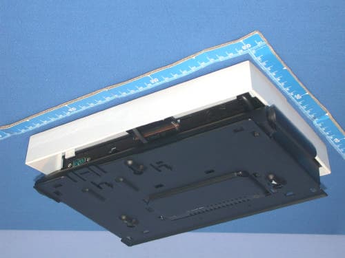
Click to zoom
Application Details
- Equipment Class
- NII - Unlicensed National Information Infrastructure TX
- Date of Grant
- May 29, 2003
- Application Purpose
- Original Equipment
- Date of Application
- May 27, 2003
- Equipment Note
- 802.11a Cardbus
- Frequency Range
- 5250.00000000 - 5350.00000000
- Company
- Proxim Wireless Corporation
- Country
- United States
Documents & Files
Document Text
Text extracted from the exhibit documents filed with the FCC. Open a document above to read the original.
Users Manual
802.11a PC Card Quick Installation Guide Quick Installation Guide Wireless TM 802.11a PC Card 54 Mbps wireless network card Other trademarks or brand names mentioned herein are trademarks or registered trademarks of their respec- tive companies. AP-2000 E062002-R01 1 Contents Introduction 1 Package Checklist 1 System Requirements 1 Applications 2 Hardware Description 2 Hardware Installation 2 Driver Installation and Configuration 3 Windows 98/Me/2000/XP Driver Installation 3 Windows 98 Configuration 6 Windows Me/2000/XP Configuration 7 Network Configuration and Planning 14 Network Topologies 14 Infrastructure Wireless LAN 14 Infrastructure Wireless LAN for Roaming Wireless PCs 14 Troubleshooting 16 Adapter Installation Problems 16 Network Connection Problems 16 The 802.11a Wireless Products Maximum Distance Table 17 Compliances 18 Federal Communication Commission Interference Statement 18 CAUTION STATEMENT: 18 FCC RF Radiation Exposure Statement 18 CSA Statement (Canada) 19 Specifications 20 Terminology 22 Contents 2 1 Introduction The Wireless TM 802.11a PC Card is a 54 Mbps wireless network card that seamlessly integrates with existing Ethernet networks to support applications such as mobile users or temporary conferences. This solution offers fast, reliable wireless connectivity with considerable cost savings over wired LANs (which include long-term maintenance overhead for cabling). Just plug wireless cards into your devices and start networking. Using this card in conjunction with a Wireless TM WA5001 802.11a Wireless Access Point, you can create an instant network that allows users on the wireless LAN to access resources on the wired LAN. Moreover, moving or expanding your network is as easy as moving or installing additional access points – no wires! Package Checklist The Wireless TM PC Card package includes: •1 Wireless TM 802.11a PC Card (AP-2000 PC Card) • 1 Driver and Utility CD-ROM • This User Guide Inform your dealer if there are any incorrect, missing, or damaged parts. If possible, retain the carton, including the original packing materials. Use them again to repack the product if there is a need to return it for repair. System Requirements Before you install the Wireless PC Card, check your system for the following requirements: • A computer with a CardBus slot • Windows 98/Me/2000/XP (Have the Windows installation CD-ROM ready for use during installation) • A minimum of 30 Mbytes of free disk space for installing the driver and utility program Other IEEE 802.11a-compliant devices installed in your service area (such as the Wireless 802.11a Access Point). 2 Applications The Wireless products offer a fast, reliable, cost-effective solution for wireless client access to the network in applications such as: • Remote access to corporate network information E-mail, file transfer, and terminal emulation. •Difficult-to-wire environments Historical or old buildings, asbestos installations, and open areas where wiring is difficult to employ. • Frequently changing environments Retailers, manufacturers, and banks which frequently rearrange the workplace or change location. • Temporary LANs for special projects or peak times Trade shows, exhibitions, and construction sites which need temporary setup for a short time period. Retailers, airline and shipping companies which need additional workstations for a peak period. Auditors who require workgroups at customer sites. • Access to databases for mobile workers Doctors, nurses, retailers, or white-collar workers who need access to databases while being mobile in a hospital, retail store, or an office campus. • SOHO users SOHO (Small Office and Home Office) users who need easy and quick installation of a small computer network. Hardware Description The Wireless PC Card is fully compliant with 802.11a wireless networking as defined in IEEE 802.11a. It can be installed in any device with a CardBus slot. Support is provided for Windows 98/Me/2000/XP. Hardware Installation 1.Turn your computer on and boot to your operating system. 2.With the CardBus adapter 68-pin connector facing the CardBus slot and the label facing up, slide the card completely into the CardBus slot as shown below. Access Point 2000 3 Driver Installation and Configuration The driver folder on the Driver/Utility CD-ROM contains the software drivers available for the Wireless TM 802.11a PC Card. Windows 98/Me/2000/XP Driver Installation You may find that these instructions do not exactly match your version of Windows. This is because these steps and screenshots were created from Windows 2000. Windows 98, Windows Millennium Edition, and Windows XP are similar, but not identical, to Windows 2000. 1.Once the card is inserted, Windows 98/Me/2000/XP will automatically detect the new hardware and prompt you to install the driver. Click “Next.” 4 2.Insert the Driver/Utility CD-ROM and click “Next.” 3.Click “Next” to copy files from the CD-ROM. Windows 98/Me/2000/XP Driver Installation 5 4.Click “Finish” to end the installation. To communicate with the Wireless 802.11a wireless devices, you may need to configure the CardBus Adapter. For Windows 98, see “Windows 98 Configuration” on page 6. For Windows Me/2000/XP see “Windows Me/2000/XP Configuration” on page 7. Driver Installation and Configuration 6 Windows 98 Configuration 1.From the “Start” menu, select “Settings” then click on “Control Panel.” 2.Double-click on the “NIC Configuration” icon. A configuration dialog box similar to the one shown in step 5 on page 10 will appear. For the remaining configuration instructions, go to page 14 and continue from Step 5. Windows Me/2000/XP Configuration 7 Windows Me/2000/XP Configuration 1.On your desktop, right click “My Computer,” click “Properties” then click the “Hardware” tab in the “System Properties” dialog box. Driver Installation and Configuration 8 2.Click “Device Manager.” 3.Click “Network adapters” then click “Wireless 802.11a PC Card.” Windows Me/2000/XP Configuration 9 4.Clic…
Text truncated - open the document above for the full version.
Attestation Statements
Proxim Corporation 935 Stewart Drive, Sunnyvale, CA 94085, USA Tel: +31 30607 6520 Fax:+31 30607 6501 1 FEDERAL COMMUNICATIONS COMMISSION DECLARATION OF CONFORMITY (DoC) For the following equipment: Product Name: 802.11a Cardbus Model No.: A13QBF-PC Trade Name: Proxim Is herewith confirmed to be in compliance with the requirements of ANSI C63.4 & FCC part 15 regulations. The test result has been shown in the ADT test report with number RF920517R02. And this compliance is subject to the following two conditions: This device may not cause harmful interference and, This device must accept any interference received, including interference that may cause undesired operation. The following local Manufacturer/Importer is responsible for this declaration: Proxim Corporation (Company Name) 935 Stewart Drive, Sunnyvale, CA 94085, USA (Company Address) TEL : +31 30607 6520 FAX : + 31 30607 6501 Mark Koop / Regulatory Compliance Manager (Name) / (Title) (Signature) / (Date) May 19, 2003
Cover Letter(s)
Proxim Corporation 935 Stewart Drive, Sunnyvale, CA 94085, USA Tel: +31 30607 6520 Fax:+31 30607 6501 FCC ID: HZB-A13QBFPC Federal Communications Commission Authorization and Evaluation Division Confidentiality Request Pursuant to Sections 0.457 and 0.459 of the Commission’s Rules, the Applicant hereby requests confidential treatment of information accompanying this Application as outlined below: Schematics Block Diagram The above materials contain trade secrets and proprietary information not customarily released to the public. The public disclosure of these matters might be harmful to the Applicant and provide unjustified benefits to its competitors. The Applicant understands that pursuant to Rule 0.457, disclosure of this Application and all accompanying documentation will not be made before the date of the Grant for this application. Sincerely, Mark Koop / Regulatory Compliance Manager Proxim Corporation Tel: +31 30607 6520 Fax: +31 30607 6501 e-mail: [email protected]
Cover Letter(s)
POWER OF ATTORNEY HZB-A13QBFPC To whom it may concern: We, the undersigned, Proxim Corporation, hereby authorize Advance Data Technology Corporation (ADT) of Taiwan to act on our behalf in all matters relating to all processes required in the FCC Part 15C approval and any communication needed with the national authority. Any and all acts carried out by ADT on our behalf shall have the same effects as acts of our own. If you have any questions regarding the authorization, please don’t hesitate to contact us. Thank you! Sincerely yours, Mark Koop / Regulatory Compliance Manager Proxim Corporation Tel: +31 30607 6520 Fax: +31 30607 6501 e-mail: [email protected] Proxim Corporation 935 Stewart Drive, Sunnyvale, CA 94085, USA Tel: +31 30607 6520 Fax:+31 30607 6501
Cover Letter(s)
FCC ID: HZB-A13QBFPC ADT No.920517R02 Limited Modular Approval Request Letter Advance Data Technology May 27, 2003 Dear Application Examiner, Proxim Corporation’s 802.11a Cardbus, FCC ID: HZB-A13QBFPC, would like to have your authorization as a limited modular approval specific to the Access Point with model name AP-2000. The requirements of Public Notice DA00-1407 have been met and shown on the following statements. 1. “The modular transmitter must have its own RF shielding.”: The radio portion of this module has been shielded, please see exhibition External Photo. 2. “The modular transmitter must have buffered modulation/data inputs.” The EUT has buffered data inputs, it is integrated in chip AR5212. 3. “The modular transmitter must have its own power supply regulation.” The chips RF converter which will influence the frequency radiation, have to be 2.5V DC powered. The PCMCIA interface provides 3.3VDC, so there are regulators in front of these chips, the part number of this regulator is TK71725SCL. 4. “The modular transmitter must comply with the antenna requirements of section 15.203 and 15.204(C).” The EUT meets the FCC antenna requirements. The spurious emission, unique antenna connector and photo of antennas are shown in the test report. 5. “The modular transmitter must be tested in a stand-alone configuration” Due to the modular be specified to Access Point with model name AP-2000, so the EUT was tested in the full system configuration. Please see section Photographs of Test Configuration in the test report. 6. “The modular transmitter must be labeled with its own FCC ID number.” Please see exhibition Label Sample for the FCC ID of this module. And also in the exhibition Users Manual, there are instructions give to the OEM on how to label the end product. FCC ID: HZB-A13QBFPC ADT No.920517R02 7. “The modular transmitter must comply with any specific rule or operating requirements applicable to the transmitter and the manufacturer must provide adequate instructions along with the module to explain any such requirements.” The EUT is compliant with all applicable FCC rules. Detail instructions for maintaining compliance are given in the Users Manual. 8. “The modular transmitter must comply with any applicable RF exposure requirements.” The EUT is compliant with all applicable RF exposure requirements. RF Exposure is addressed in the RF exposure exhibition. Please contact me if you have any further questions. Thanks for your attention. Best Regards, Eric Lin Manager of Hsinchu Certification Service Div. Advance Data Technology
External Photos
Page 1 CONSTRUCTION PHOTOS OF EUT Page 2
ID Label/Location Info
(Fig. 1) FCC ID: HZB-A13QBFPC FCC LABEL LOCATION The label will be permanently affixed at a conspicuous location on the device. Label
Internal Photos
Page 1 CONSTRUCTION PHOTOS OF EUT Page 2 Page 3 Page 4 Page 5 Page 6 Page 7 Page 8 Page 9 Page 10 Page 11 Page 12 Page 13 Page 14 Page 15
Operational Description
FCC ID: HZB-A13QBFPC Report No.920517R02 ADT No. 920517R02 Technical Description The transmitter of the EUT is powered by host equipment. The antenna is Omni-direction antenna with MMCX connector. This device is a 5GHz 802.11a Cardbus operates in both the 5GHz bands, the maximum data rate could be 108Mbps in turbo mode. For more detailed instruction, please take a look at the user’s manual. FCC 15.407(c) states : The device shall automatically discontinue transmission in case of either absence of information to transmit or operational failure. These provisions are not intended to preclude the transmission of control or signaling information or the use of repetitive codes used by certain digital technologies to complete frame or burst intervals. Applicants shall include in their application for equipment authorization a description of hoe this requirement is met. Data transmission is always initiated by software, which is then pass down through the MAC, through the digital and analog baseband, and finally to the RF chip. Several special packets (ACKs, CTS, PSPoll, etc...) are initiated by the MAC. There are the only ways the digital baseband portion will turn on the RF transmitter, which it then turns off at the end of the packet. Therefore, the transmitter will be on only while one of the aforementioned packets are being transmitted.
RF Exposure Info
FCC ID: HZB-A13QBFPC Report No.: 920517R02 ADT No.: 920517R02 RF EXPOSURE REPORT REPORT NO.: RF920517R02 MODEL NO.: A13QBF-PC ACCORDING: FCC Guidelines for Human Exposure IEEE C95.1 APPLICANT: Proxim Corporation ADDRESS: 935 Stewart Drive, Sunnyvale, CA 94085, USA ISSUED BY: Advance Data Technology Corporation LAB LOCATION: 47 14th Lin, Chiapau Tsun, Linko, Taipei, Taiwan, R.O.C. Lab Code: 200376-0 FCC ID: HZB-A13QBFPC Report No.: 920517R02 ADT No.: 920517R02 RF Exposure Measurement 1. Introduction In this document, we try to prove the safety of radiation harmfulness to the human body for our product. The limit for Maximum Permissible Exposure (MPE) specified in FCC 1.1310 is followed. The Gain of the antenna used in this product is measured in a Fully Anechoic Chamber (FAC) calibrated for antenna measurement in ADT, and also the maximum total power input to the antenna is measured. Through the Friis transmission formula and the maximum gain of the antenna, we can calculate the distance, away from the product, where the limit of MPE is reached. Although the Friis transmission formula is a far field assumption, the calculated result of that is an over-prediction for near field power density. We will take that as the worst case to specify the safety range. 2. RF Exposure Limit According to FCC 1.1310: The criteria listed in the following table shall be used to evaluate the environmental impact of human exposure to radio-frequency (RF) radiation as specified in 1.1307(b) LIMITS FOR MAXIMUM PERMISSIBLE EXPOSURE (MPE) Frequency Range (MHz) Electric Field Strength (V/m) Magnetic Field Strength (A/m) Power Density (mW/cm 2 ) Average Time (minutes) (A)Limits For Occupational / Control Exposures 300-1500......F/3006 1500-100,000......56 (B)Limits For General Population / Uncontrolled Exposure 300-1500......F/15006 1500-100,000......1.030 F = Frequency in MHz FCC ID: HZB-A13QBFPC Report No.: 920517R02 ADT No.: 920517R02 3. Friis Formula Friis transmission formula : Pd = (Pout*G) / (4*pi*r 2 ) where Pd = power density in mW/cm 2 Pout = output power to antenna in mW G = gain of antenna in linear scale Pi = 3.1416 R = distance between observation point and center of the radiator in cm Pd is the limit of MPE, 1 mW/cm 2 . If we know the maximum Gain of the antenna and the total power input to the antenna, through the calculation, we will know the MPE value at distance 20cm. Ref. : David K. Cheng, Field and Wave Electromagnetics, Second Edition, Page 640, Eq. (11-133). 4 EUT Operating condition The software provided by Manufacturer enabled the EUT to transmit and receive data at lowest, middle and highest channel individually. 5 Climate Condition The temperature and related humidity: 20 deg. C and 63 % RH 6. Classification This device is not fixed inside the host equipment, it is connected with host through wire. So it is easy to be re-located in the place where at least 20 cm far away from the body of the user. Warning statement to the user for keeping at least 20cm or more separation distance with the antenna should be included in users manual. So, this device is classified as Mobile Device. FCC ID: HZB-A13QBFPC Report No.: 920517R02 ADT No.: 920517R02 7 Test Results 7.1 Antenna Gain The maximum Gain measured in Fully Anechoic Chamber is 5dBi or 3.162(numeric). 7.2 Output Power Into Antenna & RF Exposure value at distance 20cm: FOR FREQUENCY 5.15~5.35GHz Normal Mode : Channel Channel Frequency (MHz) Output Power to Antenna (mW) Power Density (mW/cm 2 ) Limit of Power Density (mW/cm 2 ) 1518042.860.0271.0 4524044.160.0281.0 5526050.350.0321.0 8532051.400.0321.0 Turbo Mode : Channel Channel Frequency (MHz) Output Power to Antenna (mW) Power Density (mW/cm 2 ) Limit of Power Density (mW/cm 2 ) 1521035.080.0221.0 2525040.460.0251.0 3529045.710.0291.0 FCC ID: HZB-A13QBFPC Report No.: 920517R02 ADT No.: 920517R02 FOR FREQUENCY 5.725~5.850GHz Normal Mode : Channel Channel Frequency (MHz) Output Power to Antenna (mW) Power Density (mW/cm 2 ) Limit of Power Density (mW/cm 2 ) 9574538.5480.02431.0 11578539.1740.02461.0 13582538.1070.02401.0 Turbo Mode : Channel Channel Frequency (MHz) Output Power to Antenna (mW) Power Density (mW/cm 2 ) Limit of Power Density (mW/cm 2 ) 4576039.0840.02461.0 5580038.8150.02441.0
Schematics
FCC ID: HZB-A13QBFPC Report No.: RF920517R0286Issued: May 27, 2003 ADT No.: 920517R02 4.9.3 TEST PROCEDURE The transmitter output was connected to the spectrum analyzer through an attenuator. The bandwidth of the fundamental frequency was measured by spectrum analyzer with 100 kHz RBW and 100 kHz VBW. The 6 dB bandwidth is defined as the total spectrum the power of which is higher than peak power minus 6 dB. 4.9.4 DEVIATION FROM TEST STANDARD No deviation 4.9.5 TEST SETUP 4.9.6 EUT OPERATING CONDITIONS The software provided by client to enable the EUT under transmission condition continuously at lowest, middle and highest channel frequencies individually. EUT SPECTRUM ANALYZER FCC ID: HZB-A13QBFPC Report No.: RF920517R0287Issued: May 27, 2003 ADT No.: 920517R02 4.9.7 TEST RESULTS EUT 802.11a Cardbus MODEL A13QBF-PC INPUT POWER (SYSTEM) 120Vac, 60Hz ENVIRONMENTAL CONDITIONS 27deg.C, 56%RH, 978 hPa TEST MODENormalTEST BYTony Chen CHANNEL CHANNEL FREQUENCY (MHz) 6 dB BANDWIDTH (MHz) MINIMUM LIMIT (MHz) PASS/FAIL 9574516.620.5PASS 11578516.620.5PASS 13582516.620.5PASS FCC ID: HZB-A13QBFPC Report No.: RF920517R0288Issued: May 27, 2003 ADT No.: 920517R02 CH9 FCC ID: HZB-A13QBFPC Report No.: RF920517R0289Issued: May 27, 2003 ADT No.: 920517R02 CH11 FCC ID: HZB-A13QBFPC Report No.: RF920517R0290Issued: May 27, 2003 ADT No.: 920517R02 CH13 FCC ID: HZB-A13QBFPC Report No.: RF920517R0291Issued: May 27, 2003 ADT No.: 920517R02 EUT 802.11a Cardbus MODEL A13QBF-PC INPUT POWER (SYSTEM) 120Vac, 60Hz ENVIRONMENTAL CONDITIONS 27deg.C, 56%RH, 978 hPa TEST MODETurboTEST BYTony Chen CHANNEL CHANNEL FREQUENCY (MHz) 6 dB BANDWIDTH (MHz) MINIMUM LIMIT (MHz) PASS/FAIL 4576033.120.5PASS 5580033.120.5PASS FCC ID: HZB-A13QBFPC Report No.: RF920517R0292Issued: May 27, 2003 ADT No.: 920517R02 CH4 FCC ID: HZB-A13QBFPC Report No.: RF920517R0293Issued: May 27, 2003 ADT No.: 920517R02 CH5 FCC ID: HZB-A13QBFPC Report No.: RF920517R0294Issued: May 27, 2003 ADT No.: 920517R02 4.10 MAXIMUM PEAK OUTPUT POWER 4.10.1 LIMITS OF MAXIMUM PEAK OUTPUT POWER MEASUREMENT The Maximum Peak Output Power Measurement is 30dBm. 4.10.2 INSTRUMENTS Description & ManufacturerModel No.Serial No.Calibrated Until SINGLE CHANNEL POWER METERNRVS100026Mar. 06, 2004 PEAK POWER SENSOR NRV-Z32100013Mar. 06, 2004 NOTE: 1. The measurement uncertainty is less than +/- 2.6dB, which is calculated as per the NAMAS document NIS81. 2. The calibration interval of the above test instruments is 12 months and the calibrations are traceable to NML/ROC and NIST/USA. FCC ID: HZB-A13QBFPC Report No.: RF920517R0295Issued: May 27, 2003 ADT No.: 920517R02 4.10.3 TEST PROCEDURES The transmitter output was connected to the peak power meter. 4.10.4 DEVIATION FROM TEST STANDARD No deviation 4.10.5 TEST SETUP 4.10.6 EUT OPERATING CONDITIONS Same as Item 4.3.6 EUTPeak Power Meter FCC ID: HZB-A13QBFPC Report No.: RF920517R0296Issued: May 27, 2003 ADT No.: 920517R02 4.10.7 TEST RESULTS EUT 802.11a Cardbus MODEL A13QBF-PC INPUT POWER (SYSTEM) 120Vac, 60Hz ENVIRONMENTAL CONDITIONS 24deg.C, 64%RH, 978 hPa TEST MODENormalTEST BYTony Chen CHANNEL CHANNEL FREQUENCY (MHz) PEAK POWER OUTPUT (dBm) PEAK POWER LIMIT (dBm) PASS/FAIL 9574515.8630PASS 11578515.9330PASS 13582515.8130PASS EUT802.11a CardbusMODELA13QBF-PC INPUT POWER (SYSTEM) 120Vac, 60Hz ENVIRONMENTAL CONDITIONS 24deg.C, 64%RH, 978 hPa TEST MODE Turbo TEST BY Tony Chen CHANNEL CHANNEL FREQUENCY (MHz) PEAK POWER OUTPUT (dBm) PEAK POWER LIMIT (dBm) PASS/FAIL 4576015.9230PASS 5580015.8930PASS FCC ID: HZB-A13QBFPC Report No.: RF920517R0297Issued: May 27, 2003 ADT No.: 920517R02 4.10.8 LIMITS OF POWER SPECTRAL DENSITY MEASUREMENT The Maximum of Power Spectral Density Measurement is 8dBm. 4.10.9 TEST INSTRUMENTS Description & ManufacturerModel No.Serial No.Calibrated Until R&S SPECTRUM ANALYZERFSP1093.4495.30Dec. 19, 2003 NOTE: 1.The measurement uncertainty is less than +/- 2.6dB, which is calculated as per the NAMAS document NIS81. 2.The calibration interval of the above test instruments is 12 months and the calibrations are traceable to NML/ROC and NIST/USA. FCC ID: HZB-A13QBFPC Report No.: RF920517R0298Issued: May 27, 2003 ADT No.: 920517R02 4.10.10 TEST PROCEDURE The transmitter output was connected to the spectrum analyzer through an attenuator, the bandwidth of the fundamental frequency was measured with the spectrum analyzer using 3 kHz RBW and 30 kHz VBW, set sweep time = span/3 kHz. The power spectral density was measured and recorded. The sweep time is allowed to be longer than span/3 kHz for a full response of the mixer in the spectrum analyzer. 4.10.11 DEVIATION FROM TEST STANDARD No deviation 4.10.12 TEST SETUP 4.10.13 EUT OPERATING CONDITION Same as Item 4.3.6 EUT SPECTRUM FCC ID: HZB-A13QBFPC Report No.: RF920517R0299Issued: May 27, 2003 ADT No.: 920517R02 4.10.14 TEST RESULTS EUT 802.11a Cardbus MODEL A13QBF-PC INPUT POWER (SYSTEM) 120Vac, 60Hz ENVIRONMENTAL CONDITIONS 57deg. C, 56%RH, 978 hPa TEST MODENormalTEST BYTony Chen CHANNEL NUMBER CHANNEL FREQUENCY (MHz ) RF POWER LEVEL IN 3 kHz BW (dBm) MAXIMUM LIMIT (dBm) PASS/FAIL 95745 -10.828PASS 115785 -10.818PASS 135825 -11.068PASS FCC ID: HZB-A13QBFPC Report No.: RF920517R02100Issued: May 27, 2003 ADT No.: 920517R02 CH9 FCC ID: HZB-A13QBFPC Report No.: RF920517R02101Issued: May 27, 2003 ADT No.: 920517R02 CH11 FCC ID: HZB-A13QBFPC Report No.: RF920517R02102Issued: May 27, 2003 ADT No.: 920517R02 CH13 FCC ID: HZB-A13QBFPC Report No.: RF920517R02103Issued: May 27, 2003 ADT No.: 920517R02 EUT 802.11a Cardbus MODEL A13QBF-PC INPUT POWER (SYSTEM) 120Vac, 60Hz ENVIRONMENTAL CONDITIONS 57deg. C, 56%RH, 978 hPa TEST MODETurboTEST BYTony Chen CHANNEL NUMBER CHANNEL FREQUENCY (MHz ) RF POWER LEVEL IN 3 kHz BW (dBm) MAXIMUM LIMIT (dBm) PASS/FAIL 45760 -14.868PASS 55800 -14.768PASS FCC ID: HZB-A13QBFPC Report No.: RF920517R02104Issued: May 27, 2003 ADT No.: 920517R02 CH4 FCC ID: HZB-A13QBFPC Report No.: RF920517R02105Issued: May 27, 2003 ADT No.: 920517R02 CH5 FCC ID: HZB-A13QBFP…
Text truncated - open the document above for the full version.
Test Report
FCC ID: HZB-A13QBFPC Report No.: RF920517R021Issued: May 27, 2003 ADT No.: 920517R02 FCC TEST REPORT REPORT NO.: RF920517R02 MODEL NO.: A13QBF-PC PLATFORM: AP-2000, BRAND: Proxim RECEIVED: May 17, 2003 TESTED: May 22 to 26, 2003 APPLICANT: Proxim Corporation ADDRESS: 935 Stewart Drive, Sunnyvale, CA 94085, USA ISSUED BY: Advance Data Technology Corporation LAB LOCATION: No. 81-1, Lu Liao Keng, 9 Ling, Wu Lung Tsuen, Chiung Lin Hsiang, Hsin Chu Hsien, Taiwan, R.O.C. This test report consists of 119 pages in total. It may be duplicated completely for legal use with the approval of the applicant. It should not be reproduced except in full, without the written approval of our laboratory. The client should not use it to claim product endorsement by NVLAP or any government agencies. The test results in the report only apply to the tested sample. Lab Code: 200376-0 FCC ID: HZB-A13QBFPC Report No.: RF920517R022Issued: May 27, 2003 ADT No.: 920517R02 Table of Contents 1.CERTIFICATION............................................................................................................5 2.SUMMARY OF TEST RESULTS.....................................................................................6 3.GENERAL INFORMATION.............................................................................................8 3.1GENERAL DESCRIPTION OF EUT................................................................................8 3.2DESCRIPTION OF TEST MODES..................................................................................9 3.3GENERAL DESCRIPTION OF APPLIED STANDARDS....................................................9 3.4DESCRIPTION OF SUPPORT UNITS...........................................................................10 4.TEST TYPES AND RESULTS.......................................................................................12 4.1CONDUCTED EMISSION MEASUREMENT..................................................................12 4.1.1LIMITS OF CONDUCTED EMISSION MEASUREMENT.................................................12 4.1.2TEST INSTRUMENTS..................................................................................................12 4.1.3TEST PROCEDURES..................................................................................................13 4.1.4DEVIATION FROM TEST STANDARD..........................................................................13 4.1.5TEST SETUP...............................................................................................................14 4.1.6EUT OPERATING CONDITIONS..................................................................................14 4.1.7TEST RESULTS...........................................................................................................15 4.2RADIATED EMISSION MEASUREMENT......................................................................17 4.2.1LIMITS OF RADIATED EMISSION MEASUREMENT.....................................................17 4.2.2LIMITS OF UNWANTED EMISSION OUT OF THE RESTRICTED BANDS......................18 4.2.3TEST INSTRUMENTS..................................................................................................19 4.2.4TEST PROCEDURES..................................................................................................20 4.2.5DEVIATION FROM TEST STANDARD..........................................................................20 4.2.6TEST SETUP...............................................................................................................21 4.2.7EUT OPERATING CONDITIONS..................................................................................21 4.2.8TEST RESULTS...........................................................................................................22 4.2.9TEST RESULTS...........................................................................................................23 4.3PEAK TRANSMIT POWER MEASUREMENT................................................................35 4.3.1LIMITS OF PEAK TRANSMIT POWER MEASUREMENT...............................................35 4.3.2TEST INSTRUMENTS..................................................................................................35 4.3.3TEST PROCEDURE....................................................................................................36 4.3.4DEVIATION FROM TEST STANDARD..........................................................................36 4.3.5TEST SETUP...............................................................................................................36 4.3.6EUT OPERATING CONDITIONS..................................................................................36 4.3.7TEST RESULTS...........................................................................................................37 4.4PEAK POWER EXCURSION MEASUREMENT.............................................................53 4.4.1LIMITS OF PEAK POWER EXCURSION MEASUREMENT............................................53 4.4.2TEST INSTRUMENTS..................................................................................................53 4.4.3TEST PROCEDURE....................................................................................................54 4.4.4DEVIATION FROM TEST STANDARD..........................................................................54 4.4.5TEST SETUP...............................................................................................................54 4.4.6EUT OPERATING CONDITIONS..................................................................................54 FCC ID: HZB-A13QBFPC Report No.: RF920517R023Issued: May 27, 2003 ADT No.: 920517R02 4.4.7TEST RESULTS...........................................................................................................55 4.5PEAK POWER SPECTRAL DENSITY MEASUREMENT................................................56 4.5.1LIMITS OF PEAK POWER SPECTRAL DENSITY MEASUREME…
Text truncated - open the document above for the full version.
Test Report
FCC ID: HZB-A13QBFPC Report No.: RF920517R0256Issued: May 27, 2003 ADT No.: 920517R02 CHANNEL 1 FCC ID: HZB-A13QBFPC Report No.: RF920517R0257Issued: May 27, 2003 ADT No.: 920517R02 CHANNEL 4 FCC ID: HZB-A13QBFPC Report No.: RF920517R0258Issued: May 27, 2003 ADT No.: 920517R02 CHANNEL 5 FCC ID: HZB-A13QBFPC Report No.: RF920517R0259Issued: May 27, 2003 ADT No.: 920517R02 CHANNEL 8 FCC ID: HZB-A13QBFPC Report No.: RF920517R0260Issued: May 27, 2003 ADT No.: 920517R02 EUT 802.11a Cardbus MODEL A13QBF-PC MODE Turbo INPUT POWER (SYSTEM) 120Vac, 60 Hz ENVIRONMENTAL CONDITIONS 25eg. C, 66RH, 976 hPa TESTED BY Hank Chung CHANNEL CHANNEL FREQUENCY (MHz) PEAK POWER EXCURSION (dB) PEAK to AVERAGE EXCURSION LIMIT (dB) PASS/FAIL 152108.3013PASS 252507.…
Text truncated - open the document above for the full version.
Contact Information
Applicant
Ken Lim(Accounting Manager)
Technical Contact
Advance Data Technology CorporationEric Lin
[email protected]+886 3 593 5343
81-1 Luliaoken, 9th Lin, Wulung Tsuen Chiunglin · Hsinchu · Taiwan
Test Firm
Bureau Veritas CPS (H.K.) Ltd. Taoyuan BranchRichard Chen
Technical Specifications
| # | Rule Parts | Frequency Range | Power Output |
|---|---|---|---|
| 2 | 15E | 5.25 GHz - 5.35 GHz | 51.00 mW |
Other Applications from Proxim Wireless Corporation
HZB-MEGA6
Aug 12, 2026EdgeAX 6GHz Radio Module
Equipment Class
6FC - 15E 6 GHz Fixed Client
HZB-GIGA5
Sep 21, 2023Startum X5 Gigabit 5 GHz Radio
Equipment Class
NII - Unlicensed National Information Infrastructure TX
HZB-NGPAP
Apr 26, 2021NGP LC 2.4 & 5 GHz Radios
Equipment Class
NII - Unlicensed National Information Infrastructure TX
HZB-NGPLC
Mar 04, 2021NGP LC 5 GHz Radio
Equipment Class
DTS - Digital Transmission System
HZB-NGP1058W
Nov 03, 2015802.11 ac PCIe Module
Equipment Class
DTS - Digital Transmission System