HZB-B11FNFUSB802.11/b WLAN USB Adapter
Proxim Wireless Corporation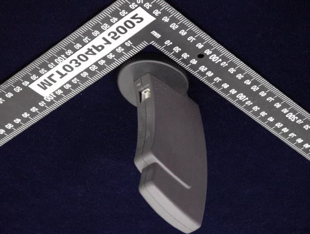
Click to zoom
Application Details
- Equipment Class
- DTS - Digital Transmission System
- Date of Grant
- May 04, 2003
- Application Purpose
- Original Equipment
- Date of Application
- May 04, 2003
- Equipment Note
- 802.11/b WLAN USB Adapter
- Frequency Range
- 2412.00000000 - 2462.00000000
- Company
- Proxim Wireless Corporation
- Country
- United States
Documents & Files
Document Text
Text extracted from the exhibit documents filed with the FCC. Open a document above to read the original.
Users Manual
Wireless USB Adapter User Manual Contents Chapter 1 About the WirelessUSB Adapter.........................3 1-1 Features...........................................................................................................3 1-2 Applications.....................................................................................................3 1-3 Product Kit......................................................................................................4 Chapter 2 Network Configuring and Planning...................5 2-1 Network Topology...........................................................................................5 2-2 Roaming..........................................................................................................6 Chapter 3 Installation............................................................................7 3-1 System Requirements......................................................................................7 3-2 Inserting the Wireless Card.............................................................................7 3-3 Installation and Uninstall Process...................................................................7 Chapter 4 Wireless Utility and Configuration..................13 4-1 Windows 98/2000 Wireless Utility................................................................13 4-2 Windows XP Wireless Utility........................................................................17 Appendix A Troubleshooting....................................................................................23 Appendix B Glossary................................................................................................24 Appendix C Specifications for Wireless Card..........................................................25 Chapter 1 About the Wireless USB Adapter This IEEE 802.11b Wireless is compatible with computer USB Adapter. As a Plug-and-Play device, Windows 95/98/2000/ME/XP will automatically recognize the wireless USB Adapter and initiate the installation process. Upon successful installation, the wireless USB Adapter will communicate seamlessly with other IEEE 802.11b wireless products. 1-1 Features 1. Supports up to 11 Mbps data rate. 2. Working range up to 800 ft. in an open environment enhances mobility. 3. Supports point-to-point and point-to-multipoint access provides increased flexibility. 4. Seamless connectivity to wired Ethernet and PC network LAN’s offers quick, trouble-free integration with existing networks. 5. Direct Sequence Spread Spectrum (DSSS) technology provides secure wireless connection. 6. Wireless connections eliminate the hassle and cost of cabling. 7. Supports a wide range of LAN (Local Area Network) Network Operating Systems (NOS) including Windows 98/2000/NT/ME/XP 8. Easy Plug and Play installation. 9. Omni - directional antenna provides wide range of reception. 10. Greater flexibility to locate or move networked PC’s 1-2 Applications This wireless USB Adapter offer a fast, reliable, cost-effective solution for wireless client access to the network. Refer below for examples : ??Remote access to corporate network information ??E-mail, file transfer and terminal emulation ??Difficult-to-wire environments ??Historic or older buildings without Ethernet wiring. ??Buildings with asbestos insulation ??Open areas where wiring is difficult to employ ??Re-layout frequently environments ??Retailers, manufacturers or other organizations that frequently rearrange the workplace or relocate ??Temporary LANs for special projects or peak time usage ??Trade shows, exhibitions and construction sites that employ temporary networks. ??Retailers, airline and shipping companies that need additional workstations for a peak period and auditors that require workgroups at customer sites. ??Access to database for mobile workers ??Medical, technical and retail specialists that require roaming access to a database or other network resources. ??SOHO (Small Office and Home Office) users ??Perfect for users that need a small, easy-to-install network that deploys rapidly. 1-3 Product Kit The wireless USB Adapter includes the following items. Ensure that the items in the following list have been included. If any of the listed items are missing, please contact your local dealer. ??One wireless USB Adapter ??One Compact Disk. The CD includes 98/2000/NT/ME/XP driver, utility, and this user manual Chapter 2 Network Configuring and Planning The wireless USB Adapter supports legacy Ethernet LAN network configuration options as defined by the IEEE 802.11b. The wireless USB Adapter can be configured as: . Ad-Hoc mode for no Access Point wireless environment. . Infrastucture mode for wireless environment with Access Point. 2-1 Network Topology An Ad-Hoc wireless LAN is a group of computers. Each computer is equipped with a wireless USB Adapter that is configured to the same radio channel in order to communicate with others. Ad-Hoc wireless LAN configurations are appropriate for branch level departments or SOHO operations. A group of wireless users and an Access Point compose a Basic Service Set (BSS). Wireless clients can talk to any computer in both wired and wireless LAN network via the Access Point. 2-2 Roaming Infrastructure mode also supports roaming capabilities for mobile users. More than one BSS can be configured as an Extended Service Set (ESS). The continuous network allows users to roam freely within an ESS. All wireless USB Adapter and Access Point within one ESS must be configured with the same ESSID in order to utilize the roaming function. Proper Access Point positioning with a clear radio signal can greatly enhance wireless performance. Chapter 3 Installation 3-1 System Requirements In order to install and use the wireless USB Adapter in your notebook computer, your notebook system must meet the following requirements: ??USB interface ??CD-ROM Drive 3-2 Inserting the Wireless Card 1. Locate an available USB Adapter. 2. With the USB AD…
Text truncated - open the document above for the full version.
Cover Letter(s)
From: Country Huang [[email protected]] Sent: Tuesday, April 29, 2003 9:07 PM To: Mike Kuo Subject: Re: Proxim Corporation, FCC ID:HZBB11FNFUSB, AN03T2800 Dear Mike: 1. We send the updata testing report to CCS web. 2. Could you help to correct the FCC ID of Form 731? or How do we do for correct the FCC ID of Form 731? Thank your help!!! Best Regards! Country Huang Max Light Technology Co.,Ltd TEL: 886-2-2663-3486 FAX: 886-2-2663-3582 E-Mail: [email protected] ----- Original Message ----- From: "Mike Kuo" <[email protected]> To: <[email protected]> Sent: Tuesday, April 29, 2003 10:04 AM Subject: FW: Proxim Corporation, FCC ID:HZBB11FNFUSB, AN03T2800 > > > -----Original Message----- > From: CERTADM > Sent: Monday, April 28, 2003 7:02 PM > To: '[email protected]' > Subject: Proxim Corporation, FCC ID:HZBB11FNFUSB, AN03T2800 > > > Notice_content > ------------- > Question #1: The FCC ID number entered on the TCB application is > HZBB11FNFUSB but the FCC ID label format listed the FCC ID:HZB-B11FNFUSB. > Please confirm which FCC ID number shall be used for this application. > > Question #2: The AC line conducted tests were investigated from 450kHz to > 30MHz. To avoid to have grant note "05" NOTE- The manufacture and > importation of this device must cease on July 10, 2005 pursuant to 15.37(j) > or 18.123 transition provisions adopted under FCC 02-157 (ET Docket 98-80) > apply to this application, please provide new AC line conducted data from > 150kHz to 30MHz per CISPR 22 Class B requirements. > > FYI: Section 3.6.4 of test report, when peak detector is used for measuring > radiated spurious emission, the technical limits shall compare to Average > limits. If peak readings are over the average limits, you are required to > demonstrate peak measurement compliance as well. In this case, since the > peak readings are below average limits (54dBuV/m), you are not required to > provide average readings. > > Best Regards > > Mike Kuo > The items indicated above must be submitted before processing can continue > on the above referenced application. Failure to provide the requested > information within 60 days of the original e-mail date may result in > application dismissal and forfeiture of the filing fee. Also, please note > that partial responses increase processing time and should not be submitted. > Any questions about the content of this correspondence should be directed to > the e-mail address listed below the name of the sender.
External Photos
MAX LIGHT Report Number: MLT00304P15002 FCC ID: HZB-B11FNFUSB Technology Lab MAX LIGHT Report Number: MLT00304P15002 FCC ID: HZB-B11FNFUSB Technology Lab
ID Label/Location Info
MAX LIGHT Report Number: MLT00304P15002 FCC ID: HZB-B11FNFUSB Technology Lab Label Format: Label Position: This device complies with Part15 of the FCC Rules. Operation is subject to the following two conditions: (1) This device may not cause harmful interference,and (2) This device must accept any interference received ,including. Interference that may cause undesired operation. Model : B11FNF-USB FCC ID : HZB-B11FNFUSB MADE IN TAIWAN Rear View Equipment Lable 1.5cmX2.0cm
Internal Photos
MAX LIGHT Report Number: MLT00304P15002 FCC ID: HZB-B11FNFUSB Technology Lab MAX LIGHT Report Number: MLT00304P15002 FCC ID: HZB-B11FNFUSB Technology Lab MAX LIGHT Report Number: MLT00304P15002 FCC ID: HZB-B11FNFUSB Technology Lab
RF Exposure Info
MAX LIGHT MEASUREMENT REPORT Report Number: MLT0304P15002 FCC ID: HZB-B11FNFUSB Technology Lab M M a a x x i i m m u u m m P P e e r r m m i i s s s s i i b b l l e e E E x x p p o o s s u u r r e e EUT : Wireless USB Dongle Card Applicant : Proxim Corporation 935 Steward Drive, Sunnyvale, CA 94085, USA Manufacturer : AMBIT MICROSYSTEMS CORPORATION. 5F-1, 5 Hsin-An Road, Hsinchu Scicnce-Based Industrial Par k, Taiwan Model No : B11FNF-USB FCC ID : HZB-B11FNFUSB Basis of Calculations: E^2/3770 = S, mW/cm2 E, V/ m = (Pwatts*Ggai n*30)^.5/d, meters d = ((Pwatts*G*30)/3770*S))^0.5 Pwatts*Ggain = 10^(PdBm-30+GdBi)/10) Test Result: Max RF Power (dBm) TX Antenna Gain (dBi) MPE Safe Distance(cm) 11.92 1.72 1.4 NOTE: For mobile or fixed location transmitters, minimum separation distance is 20cm, even if calculations indicate MPE distance is less.
Test Report
P P a a r r t t 1 1 5 5 S S u u b b p p a a r r t t B B & & C C ( ( 1 1 5 5 . . 2 2 4 4 7 7 ) ) Product : Wireless USB Dongle Card Applicant : Proxim Corporation FCC ID : HZB-B11FNFUSB Model : B11FNF-USB Report No. : MLT0304P15002 Test Date : October 31.2002 Test By Max Light Technology Co.,Ltd. Room 5, 8F, No.125, Section 3 Roosevelt Road, Taipei, Taiwan., R.O.C. Tel: 886-2-2363-2447 Fax: 886-2-2363-2597 T T h h e e t t e e s s t t r r e e p p o o r r t t c c o o n n s s i i s s t t s s o o f f 6 6 9 9 p p a a g g e e s s i i n n t t o o t t a a l l . . I I t t m m a a y y b b e e d d u u p p l l i i c c a a t t e e d d c c o o m m p p l l e e t t e e l l y y f f o o r r l l e e g g a a l l u u s s e e w w i i t t h h t t h h e e a a l l l l o o w w a a n n c c e e o o f f t t h h e e a a p p p p l l i i c c a a n n t t . . I I t t s s h h a a l l l l n n o o t t b b e e r r e e p p r r o o d d u u c c e e d d e e x x c c e e p p t t i i n n f f u u l l l l , , w w i i t t h h o o u u t t t t h h e e w w r r i i t t t t e e n n a a p p p p r r o o v v a a l l o o f f o o u u r r l l a a b b o o r r a a t t o o r r y y . . MAX LIGHT MEASUREMENT REPORT Page: 2/69 Report Number: MLT00304P15002 FCC ID: HZB-B11FNFUSB Technology Lab Table of Contents : MAX LIGHT MEASUREMENT REPORT Page: 3/69 Report Number: MLT00304P15002 FCC ID: HZB-B11FNFUSB Technology Lab CERTIFICATION We here by verify that : The test data, data evaluation, test procedures and equipment configurations shown in this report were made in accordance with the procedures given in ANSI C63.4-1992. All test were conducted by MLT(Max Light Technology Co.,Ltd) Room 5, 8F, No.125, Section 3 Roosevelt Road, Taipei, Taiwan, R.O.C Also, we attest to the accuracy of each. We further submit that the energy emitted by the sample EUT tested as described in the report is in compliance with Class B radiated and conducted emission limit of FCC Rules Part 15 Subpart B & C (15.247). EUT : Wireless USB Dongle Card Applicant : Proxim Corporation 935 Steward Drive, Sunnyvale, CA 94085, USA Manufacturer : AMBIT MICROSYSTEMS CORPORATION. 5F-1, 5 Hsin-An Road, Hsinchu Scicnce-Based Industrial Par k, Taiwan Model No : B11FNF-USB FCC ID : HZB-B11FNFUSB Prepared by : Approved by : MAX LIGHT MEASUREMENT REPORT Page: 4/69 Report Number: MLT00304P15002 FCC ID: HZB-B11FNFUSB Technology Lab 1.1 Introduction The following measurement report is submitted on behalf of AMBIT Microsystems Corporation. . In support of a Class B Digital Device certification in accordance with Part2 Subpart J and Part 15 Subpart A And B&C of the Commission’s and Regulations. 1.2 Description of EUT EUT : Wireless USB Dongle Card Applicant : Proxim Corporation 935 Steward Drive, Sunnyvale, CA 94085, USA Manufacturer : AMBIT MICROSYSTEMS CORPORATION. 5F-1, 5 Hsin-An Road, Hsinchu Scicnce-Based Industrial Park, Taiwan Model No : B11FNF-USB FCC ID : HZB-B11FNFUSB Power Type : Powered by PC Frequency of Channel : See Next page Type of Modulation : Direct Sequence Spread Spectrum Type of Antenna : Printed Antenna During testing the EUT was operated at Tx or Rx mode for each emission measured. This was done in order to ensure that maximum emission levels were attained. MAX LIGHT MEASUREMENT REPORT Page: 5/69 Report Number: MLT00304P15002 FCC ID: HZB-B11FNFUSB Technology Lab Frequency of Each Channel (Working Frequency) Channel No. Frequency (MHz) 01 2412 02 2417 03 2422 04 2427 05 2432 06 2437 07 2442 08 2447 09 2452 10 2457 11 2462 MAX LIGHT MEASUREMENT REPORT Page: 6/69 Report Number: MLT00304P15002 FCC ID: HZB-B11FNFUSB Technology Lab 1.3 Summary Of Tests 47 CFR Part 15 Subpart C Reference Test Results Note 15.107 AC Power Conducted Emission PASS 15.247(c) Transmitter Radiated Emissions PASS 15.247(b) Max. Output Power PASS 15.247(a)(2) 6dB RF Bandwidth PASS 15.247(d) Max. Power Density PASS 15.247(c) Out of Band Conducted Spurious Emission PASS 15.247(c) Band Edge Measurement PASS 15.247(e) Processing Gain of Direct Sequence PASS Provided by Applicant 15.203 Antenna Requirement PASS MAX LIGHT MEASUREMENT REPORT Page: 7/69 Report Number: MLT00304P15002 FCC ID: HZB-B11FNFUSB Technology Lab 1.4 Description of Support Equipment In order to construct the minimum system which required by the ANSI C63.4-1991, following equipments were used as the support units. Computer : IBM Model No. : 16W Serial No. : BNC345M FCC ID : FCC DOC Keyboard : IBM Model No. : KB-9930 Serial No. : 09N5395 FCC ID : FCC DOC Monitor : IBM Model No. : 10L6145 030 Serial No. : 23-092079 FCC ID : FCC DOC Mouse : IBM Model No. : 0180-05N Serial No. : 23-96142 FCC ID : EMJMUSJJ Printer : PANASONIC Model No. : KX-P1080I Serial No. : 7CKAKE98933 FCC ID : ACJ5Z6KX-P10801 FCC ID : FCC(DOC) Modem : Askey (External Fax / Data Modem) Model No. : WS1414VE Serial No. : IAH-10811 FCC ID : H8N1414VE MAX LIGHT MEASUREMENT REPORT Page: 8/69 Report Number: MLT00304P15002 FCC ID: HZB-B11FNFUSB Technology Lab 1.4 Configuration of System Under Test During testing the EUT(USB Wireless)’s USB port connected to the USB port of IBM computer. So there is No need for additional Ethernet card. A mouse was connected to the mouse port of IBM PC. and A keyboard was connected to the mouse port of IBM PC. And a printer was connected to the parallel port. A external modem connected the serial port and the external modem connected with two unterminated telephone cables on the line and phone jack. TEST SITE Power Supply PC Monitor Printer Modem Keyboard Mouse EUT RJ11C Cables RS-232 RS-232 USB Cable MAX LIGHT MEASUREMENT REPORT Page: 9/69 Report Number: MLT00304P15002 FCC ID: HZB-B11FNFUSB Technology Lab 1.6 Test Procedure All measurements contained in this report were performed according to the techniques described in Measurement procedure ANSI C63.4-1992 "Measurement of unIntentional Radiators." 1.7 General Test Condition The conditions under which the EUT operates were varied to determine their effect on the equipment's emission characteristics. The fi…
Text truncated - open the document above for the full version.
Test Setup Photos
MAX LIGHT MEASUREMENT REPORT Page: 11/69 Report Number: MLT00304P15002 FCC ID: HZB-B11FNFUSB Technology Lab 2.3 Test Configuration: Front View of The Test Configuration MAX LIGHT MEASUREMENT REPORT Page: 12/69 Report Number: MLT00304P15002 FCC ID: HZB-B11FNFUSB Technology Lab Rear View of The Test Configuration MAX LIGHT MEASUREMENT REPORT Page: 21/69 Report Number: MLT00304P15002 FCC ID: HZB-B11FNFUSB Technology Lab 3.3 Test Configuration: Front View of The Test Configuration MAX LIGHT MEASUREMENT REPORT Page: 22/69 Report Number: MLT00304P15002 FCC ID: HZB-B11FNFUSB Technology Lab Rear View of The Test Configuration
Contact Information
Applicant
Ken Lim(Accounting Manager)
Test Firm
Max Light Technology Co., Ltd.Jesse Tien
Technical Specifications
| # | Rule Parts | Frequency Range | Power Output |
|---|---|---|---|
| 1 | 15C | 2.41 GHz - 2.46 GHz | 16.00 mW |
Other Applications from Proxim Wireless Corporation
HZB-MEGA6
Aug 12, 2026EdgeAX 6GHz Radio Module
Equipment Class
6FC - 15E 6 GHz Fixed Client
HZB-GIGA5
Sep 21, 2023Startum X5 Gigabit 5 GHz Radio
Equipment Class
NII - Unlicensed National Information Infrastructure TX
HZB-NGPAP
Apr 26, 2021NGP LC 2.4 & 5 GHz Radios
Equipment Class
NII - Unlicensed National Information Infrastructure TX
HZB-NGPLC
Mar 04, 2021NGP LC 5 GHz Radio
Equipment Class
DTS - Digital Transmission System
HZB-NGP1058W
Nov 03, 2015802.11 ac PCIe Module
Equipment Class
DTS - Digital Transmission System