HZB-PCI-8482ORiNOCO 802.11 a/b/g PCI Card
Proxim Wireless Corporation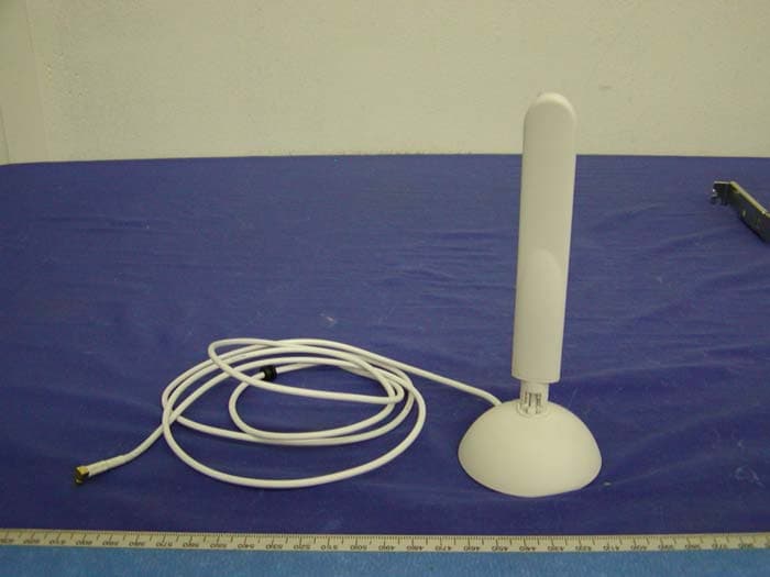
Click to zoom
Application Details
- Equipment Class
- NII - Unlicensed National Information Infrastructure TX
- Date of Grant
- Sep 29, 2004
- Application Purpose
- Original Equipment
- Date of Application
- Sep 29, 2004
- Equipment Note
- ORiNOCO 802.11 a/b/g PCI Card
- Frequency Range
- 5280.00000000 - 5320.00000000
- Company
- Proxim Wireless Corporation
- Country
- United States
Documents & Files
Document Text
Text extracted from the exhibit documents filed with the FCC. Open a document above to read the original.
Users Manual
ORiNOCO Wireless Client User Guide ORiNOCO Wireless Client User Guide Copyright 2003 Proxim Corporation, Sunnyvale, CA. All rights reserved. Covered by one or more of the following U.S. patents: 5,231,634; 5,875,179; 6,006,090; 5,809,060; 6,075,812; 5,077,753. This user guide and the software described in it are copyrighted with all rights reserved. No part of this publication may be reproduced, transmitted, transcribed, stored in a retrieval system, or translated into any language in any form by any means without the written permission of Proxim Corporation. Trademarks ORiNOCO is a registered trademark, 2X, Proxim, and the Proxim logo are trademarks of Proxim Corporation. All other trademarks mentioned herein are the property of their respective owners. 65490/B ORiNOCO Wireless Client User Guide Table of Content 3 TABLE OF CONTENT CHAPTER 1 INTRODUCTION.........................................................................5 1-1 INTRODUCING THE ORINOCO WIRELESS CLIENT...............................................5 1-2 DIFFERENCE BETWEEN ORINOCO 802.11 WIRELESS CLIENT PRODUCTS.................5 1-3 USING A WIRELESS LOCAL AREA NETWORK.....................................................6 1-4 PRODUCT PACKAGE..................................................................................6 1-5 SYSTEM REQUIREMENTS AND SPECIFICATIONS..................................................7 1-5-2 INTEROPERABILITY.................................................................................9 CHAPTER 2 INSTALLATION........................................................................10 2-1 PRE-INSTALLATION CONSIDERATIONS...........................................................10 2-2 WINDOWS ME AND WINDOWS 98 SE INSTALLATION CD REQUIREMENT...............11 2-3 PROXIM CLIENT UTILITY INSTALLATION.........................................................11 CHAPTER 3 WIRELESS TOPOLOGIES...........................................................17 3-1 INTRODUCTION......................................................................................17 3-2 PEER-TO-PEER GROUP.............................................................................17 3-3 ACCESS POINT INFRASTRUCTURE................................................................18 CHAPTER 4 PROXIM CLIENT UTILITY CONFIGURATION................................22 4-1 PROXIM CLIENT UTILITY ICON....................................................................22 4-2 CURRENT STATUS TAB..............................................................................23 4-3 PROFILE MANAGEMENT...........................................................................25 4-4 DIAGNOSTIC TAB....................................................................................45 4-5 ACTION MENU.......................................................................................46 4-6 CONFIGURING YOUR WIRELESS NETWORKING SETTINGS WITH WINDOWS XP..........47 CHAPTER 5 TROUBLESHOOTING................................................................49 5-1 HOW TO OBTAIN HELP WITH YOUR LAN INSTALLATION.....................................49 5-2 COMMON INSTALLATION PROBLEMS............................................................49 5-3 CONFIGURING NETWORKING CLIENTS AND PROTOCOLS.....................................50 5-4 UNINSTALLING AN ORINOCO WIRELESS CLIENT.............................................51 5-5 RANGE................................................................................................54 5-6 LED INDICATORS...................................................................................55 5-7 COMMON TECHNICAL SUPPORT QUESTIONS...................................................55 ORiNOCO Wireless Client User Guide Table of Content 4 APPENDIX A - SPECIFICATIONS.................................................................57 A-1 TECHNICAL SPECIFICATIONS......................................................................57 APPENDIX B WARRANTY AND REGULATORY INFORMATION.......................61 B-1 LIMITED WARRANTY, DISCLAIMER, LIMITATION OF LIABILITY.............................61 B-2 REGULATORY INFORMATION......................................................................62 APPENDIX C TECHNICAL SUPPORT AND GLOSSARY....................................65 C-1 TECHNICAL SUPPORT CONTACT INFORMATION................................................65 C-2 GLOSSARY...........................................................................................67 ORiNOCO Wireless Client User Guide Chapter 2 Installation 5 1 Chapter 1 Introduction 1-1 Introducing the ORiNOCO Wireless Client Congratulations on your purchase of an ORiNOCO Wireless Client, a high performance wireless LAN adapter card that complies with the IEEE 802.11a, 802.11b and/or 802.11g wireless standards. (Standards support varies by client product) This user manual covers the following ORiNOCO Wireless Client products: l ORiNOCO 11a/b/g ComboCard l ORiNOCO 11b/g PC Card l ORiNOCO 802.11a/b ComboCard l ORiNOCO 11a/b/g PCI Card The basic installation and client utility setting described in the following chapters can be applied to all four products; only some of the specifications are different. These differences are explained later in this chapter. The ORiNOCO Wireless Client supports Windows XP, Windows 2000, Windows Millennium Edition (ME), and Windows 98 Second Edition (SE). Computers with an ORiNOCO Wireless Client installed “look” like standard network nodes to the operating system. The ORiNOCO Wireless Client can be used with other 802.11a, 802.11b or 802.11g devices to form a stand-alone wireless Peer-to-Peer Group* or used in conjunction with an Access Point infrastructure to provide mobile clients with wireless access to an Ethernet network. Proxim is a leading manufacturer of wireless networking equipment. Proxim’s unmatched expertise in radio networking technology, combined with the company’s extensive experience serving the communication needs of the mobile…
Text truncated - open the document above for the full version.
Users Manual
ORiNOCO Wireless Client User Guide Chapter 4 Proxim Client Utility Configuration 31 Per User Key – Defines the unique encryption key for network configuration security. The Per User key is used with many authentication mechanism and encryption. Shared Keys – Determines a set of shared encryption keys (First, Second, Third, Fourth) used for wireless encryption and security. At least one Shared Key field must be populated to enable security using a shared key. If more then one key is defined then click the appropriate radio button to select a key as the default encryption key. Key Length – The options for Key Length are u 64 bit encryption (10 digits in HEX mode) u 128 bit encryption (26 digits in HEX mode) u 152 bit encryption (32 digits in HEX mode) The number of characters that may be entered in the encryption key field will be automatically determined by the Key length setting. Setting WPA PassPhrase Encryption WPA is a new standard-based wireless security solution developed by the Wi-Fi Alliance. WPA also supports the WEP (Wired Equivalent Privacy) security standard. Microsoft provides a security patch called “Windows XP Support Patch for Wireless Protected Access” on its website for free download and it works only with Windows XP. The WPA encryption is supported on Windows XP Professional and Windows XP Home Edition. There are two types of WPA security: l WPA-PSK (with no server) – it uses the so-called “pre-shared key” as the security key. A pre-shared key is basically a password that is between eight and 63 characters long. It can be any combination of letters, numbers, and other characters. This is the typical mode that is used in a home environment. l WPA (with server) – it is a system where a RADIUS server distributes the keys to the clients automatically. It is typically used in a business environment. To enable WPA with a passphrase (WPA-PSK), select Pre-Shared Keys from the Security Options list and place a check mark in the WPA box. ORiNOCO Wireless Client User Guide Chapter 4 Proxim Client Utility Configuration 32 Figure 4-12 Defined Pre-Shared Keys Icon with WPA Selected The Define WPA PSK window appears as shown in Figure 4-13. Enter your passphrase text strings to complete the configuration process. Figure 4-13 Defined WPA PassPhrase Setting Dynamic Security Authentication The Dynamic Security setting prevents unauthorized network access; a network RADIUS server must authenticate each user before he/she gains access to the network. To configure the Dynamic Security settings for a particular profile, select Dynamic Security and select TLS mode (Figure 4-14), PEAP mode (Figure 4-16), or LEAP mode (Figure 4-19) on the ORiNOCO Wireless Client User Guide Chapter 4 Proxim Client Utility Configuration 33 drop-down menu. The LEAP mode on the drop-down menu can only be seen when the WPA checkbox is not selected, because the WPA does not apply to the LEAP function. When selected, click the Configure button to configure the settings described below. Figure 4-14 Dynamic Security with TLS Authentication Define Certificate The Define Certificate dialog appears after you click the Configure button. The field name “Select a Certificate” that can only be seen under the TLS mode is designed to authenticate the user to the RADIUS (Remote Authentication Dial-In Service) server from the drop-down menu. Figure 4-15 Define Certificate for TLS Mode ORiNOCO Wireless Client User Guide Chapter 4 Proxim Client Utility Configuration 34 ♦ Use Any Certificate Authority – Click this radio button to use any Certificate Authority for authentication. ♦ Choose a Certificate Authority – Click this radio button and choose the desired Certificate Authority for authentication from the drop-down menu. ♦ Server/Domain Name – Enter either the RADIUS server name or domain name for your RADIUS server. ♦ Login Name – Enter the RADIUS server login name. Select “PEAP” from the drop-down menu under the Dynamic Security mode to configure the WPA authentication for PEAP as shown in Figure 4-16 and Figure 4-17. Figure 4-16 Dynamic Security with PEAP Authentication ORiNOCO Wireless Client User Guide Chapter 4 Proxim Client Utility Configuration 35 Figure 4-17 Define Certificate for PEAP Mode The “Define User Information” is for PEAP and LEAP mode only. Click the Define User Information button and fill in the Define User Information dialog as shown in Figure 4-18. Figure 4-18 Define User Information for PEAP Mode Select “LEAP” from the drop-down menu to set the Dynamic Security method to LEAP as shown in Figure 4-19 and Figure 4-20. ORiNOCO Wireless Client User Guide Chapter 4 Proxim Client Utility Configuration 36 Figure 4-19 Dynamic Security with LEAP Authentication Figure 4-20 Define User Information for LEAP Mode 4-3-2-1 Setting up WPA in Windows XP Follow the instructions below to set up WPA in “ Windows wireless network utility”. 1. Under Windows XP, click “Start > Control Panel > Network Connections”. ORiNOCO Wireless Client User Guide Chapter 4 Proxim Client Utility Configuration 37 2. Right-click on “Wireless Network Connection”, and select “Properties”. 3. Clicking on the “Wireless Networks” tab will display the following screen. Make sure the “Use Windows to configure my wireless network settings” box is checked. 4. Under the “Wireless Networks” tab, click the “Configure” button and you will see the following screen. ORiNOCO Wireless Client User Guide Chapter 4 Proxim Client Utility Configuration 38 5. Select “WPA” under “Network Authentication”. 6. Select “TKIP” or “AES” under “Data Encryption”. This setting has to be identical to the Access Point that you set up. 7. For Home or Small Business User, enter your encryption key in the “Network Key” box. It can be from eight to 63 characters and can be letters, numbers, or symbols. You must use the very same key on all the clients that you set up. If you are using this computer to connect to a corporate network that includes a RADIUS server, consult your network adm…
Text truncated - open the document above for the full version.
Cover Letter(s)
PROXIM CONFIDENTIAL 935 Stewart Drive Sunnyvale CA 94085 P: 408 731 2700 F: 408 731 3670 www.proxim.com Federal Communications Commission Authorization and Evaluation Division Confidentiality Request regarding application for certification of FCC ID: (HZB-PCI-8482) Pursuant to Sections 0.457 and 0.459 of the Commission’s Rules, we hereby request confidential treatment of information accompanying this application as outlined below: (List exhibits here) 1. Schematic 2. Block Diagram 3. Theory of Operation The above materials contain trade secrets and proprietary information not customarily released to the public. The public disclosure of these materials may be harmful to the applicant and provide unjustified benefits to its competitors. The applicant understands that pursuant to Section 0.457 of the Rules, disclosure of this application and all accompanying documentation will not be made before the date of the Grant for this application. Sincerely, (Signature) : (Printed name) : Mohammad Sa-id Title : Regulatory Compliance Manager
External Photos
Proxim Corporation FCC ID: HZB-PCI-8482 EXHIBIT C - EUT PHOTOGRAPHS Desktop and Antenna – Front View Desktop and Antenna – Rear View Proxim Corporation FCC ID: HZB-PCI-8482 Antenna View
ID Label/Location Info
EXHIBIT A - FCC ID LABEL INFORMATION Proposed FCC ID Label Proposed Label Location on Notebook Component Side of EUT / Label Location FCC ID: HZB-PCI-8482 This device complies with Part 15 o the FCC Rules. Operation is subject to the following two conditions: (1) this device may not cause harmful interference, and (2) this device must accept any interference received, including interference that may cause undesired operation. 2.1875" 1.0"
RF Exposure Info
§1.1307(b)(1) & §2.1093 - RF EXPOSURE According to §15.247(b)(4) and §1.1307(b)(1), systems operating under the provisions of this section shall be operated in a manner that ensures that the public is not exposed to radio frequency energy level in excess of the Commission’s guidelines. According to §1.1310 and §2.1093 RF exposure is calculated. Limits for General Population/Uncontrolled Exposure Frequency Range (MHz) Electric Field Strength (V/m) Magnetic Field Strength (A/m) Power Density (mW/cm 2 ) Averaging Time (minute) Limits for General Population/Uncontrolled Exposure 0.3-1.34 614 1.63 *(100) 30 1.34-30 824/f 2.19/f *(180/f 2 ) 30 30-300 27.5 0.073 0.2 30 300-1500 / / f/1500 30 1500-100,000 / / 1.0 30 f = frequency in MHz * = Plane-wave equivalent power density MPE Prediction Predication of MPE limit at a given distance Equation from page 18 of OET Bulletin 65, Edition 97-01 S = PG/4πR² Where: S = power density P = power input to antenna G = power gain of the antenna in the direction of interest relative to an isotropic radiator R = distance to the center of radiation of the antenna 2400 – 2483.5 MHz: Maximum peak output power at antenna input terminal: 20.12 (dBm ) Maximum peak output power at antenna input terminal: 102.8 (mW) Prediction distance: 20 (cm) Predication frequency: 2400 (MHz) Antenna Gain (typical): 5 (dBi) antenna gain: 3.16 (numeric) Power density at predication frequency at 20 cm: 0.064 (mW/cm 2 ) MPE limit for uncontrolled exposure at prediction frequency: 1.0 (mW/cm 2 ) 5150 – 5250 MHz: Maximum peak output power at antenna input terminal: 16.07 (dBm ) Maximum peak output power at antenna input terminal: 40.5 (mW) Prediction distance: 20 (cm) Predication frequency: 5200 (MHz) Antenna Gain (typical): 5 (dBi) antenna gain: 3.16 (numeric) Power density at predication frequency at 20 cm: 0.026 (mW/cm 2 ) MPE limit for uncontrolled exposure at prediction frequency: 1.0 (mW/cm 2 ) 5250 – 5350 MHz: Maximum peak output power at antenna input terminal: 17.14 (dBm ) Maximum peak output power at antenna input terminal: 51.8 (mW) Prediction distance: 20 (cm) Predication frequency: 5300 (MHz) Antenna Gain (typical): 5 (dBi) antenna gain: 3.16 (numeric) Power density at predication frequency at 20 cm: 0.033 (mW/cm 2 ) MPE limit for uncontrolled exposure at prediction frequency: 1.0 (mW/cm 2 ) 5725 – 5850 MHz: Maximum peak output power at antenna input terminal: 17.58 (dBm ) Maximum peak output power at antenna input terminal: 57.3 (mW) Prediction distance: 20 (cm) Predication frequency: 5800 (MHz) Antenna Gain (typical): 5 (dBi) antenna gain: 3.16 (numeric) Power density at predication frequency at 20 cm: 0.036 (mW/cm 2 ) MPE limit for uncontrolled exposure at prediction frequency: 1.0 (mW/cm 2 ) Test Result The EUT is a mobile device. The power density levels at 20 cm for each band are 0.064 mW/cm, 0.026 mW/cm, 0.033 mW/cm, 0.036 mW/cm for each band , which are all below the uncontrolled limit of 1.0mW/cm 2 . Note: The WLAN cannot transmit simultaneously with the UNII.
Test Report
Note: The test report is specially limited to the use of the above client company and the product model only. It may not be duplicated without prior written consent of Bay Area Compliance Laboratory Corporation. This report must not be used by the client to claim product certification, approval, or endorsement by NVLAP, NIST or any agency of the U.S. Government. FCC PART 15.247 & 15.407 EMI MEASUREMENT AND TEST REPORT For Proxim Corporation 935 Stewart Drive, Sunnyvale, CA 94085, USA FCC ID: HZB-PCI-8482 This Report Concerns: Original Report Equipment Type: 802.11a/b/g PCI Card Test Engineer: Ming Jing Report No.: R0408262 Report Date: 2004-09-16 Reviewed By: Ling Zhang Prepared By: Bay Area Compliance Laboratory Corporation (BACL) 230 Commercial Street Sunnyvale, CA 94085 Tel: (408) 732-9162 Fax: (408) 732 9164 Proxim Corporation FCC ID: HZB-PCI-8482 Report # R0408262Rpt Page 2 of 86 FCC Part 15.247 & 15.407 Test Report TABLE OF CONTENTS FCC PART 15.247 & 15.407 .........................................................................................................................................1 GENERAL INFORMATION.......................................................................................................................................4 PRODUCT DESCRIPTION FOR EQUIPMENT UNDER TEST (EUT) ....................................................................................4 OBJECTIVE...................................................................................................................................................................4 RELATED SUBMITTAL(S)/GRANT(S).............................................................................................................................4 TEST METHODOLOGY..................................................................................................................................................4 TEST FACILITY.............................................................................................................................................................4 SYSTEM TEST CONFIGURATION ..........................................................................................................................6 JUSTIFICATION.............................................................................................................................................................6 EUT EXERCISE SOFTWARE..........................................................................................................................................6 SPECIAL ACCESSORIES.................................................................................................................................................6 SCHEMATICS / BLOCK DIAGRAM.................................................................................................................................6 EQUIPMENT MODIFICATIONS.......................................................................................................................................6 SUPPORT EQUIPMENT LIST AND DETAILS....................................................................................................................6 EXTERNAL I/O CABLING LIST AND DETAILS...............................................................................................................6 CONFIGURATION OF TEST SYSTEM..............................................................................................................................7 TEST SETUP BLOCK DIAGRAM.....................................................................................................................................7 SUMMARY OF TEST RESULTS ...............................................................................................................................8 §15.203 - ANTENNA REQUIREMENT......................................................................................................................9 STANDARD APPLICABLE..............................................................................................................................................9 §15.205, §15.209(A), §15.407(B)(5), §15.407(B)(6) - SPURIOUS RADIATED EMISSION..................................10 MEASUREMENT UNCERTAINTY..................................................................................................................................10 EUT SETUP................................................................................................................................................................11 SPECTRUM ANALYZER SETUP....................................................................................................................................11 TEST EQUIPMENT LIST AND DETAILS.........................................................................................................................11 TEST PROCEDURE......................................................................................................................................................12 CORRECTED AMPLITUDE & MARGIN CALCULATION.................................................................................................12 SUMMARY OF TEST RESULTS.....................................................................................................................................12 §15.207(A) - CONDUCTED EMISSIONS.................................................................................................................24 MEASUREMENT UNCERTAINTY..................................................................................................................................24 EUT SETUP................................................................................................................................................................24 SPECTRUM ANALYZER SETUP....................................................................................................................................24 TEST EQUIPMENT LIST …
Text truncated - open the document above for the full version.
Test Setup Photos
Proxim Corporation FCC ID: HZB-PCI-8482 EXHIBIT B - TEST SETUP PHOTOGRAPHS Conducted Emission Proxim Corporation FCC ID: HZB-PCI-8482 Radiated Emission
Contact Information
Applicant
Ken Lim(Accounting Manager)
Test Firm
Bay Area Compliance LaboratoryJohn Chan
Technical Specifications
| # | Rule Parts | Frequency Range | Power Output |
|---|---|---|---|
| 2 | 15E | 5.28 GHz - 5.32 GHz | 52.00 mW |
Other Applications from Proxim Wireless Corporation
HZB-MEGA6
Aug 12, 2026EdgeAX 6GHz Radio Module
Equipment Class
6FC - 15E 6 GHz Fixed Client
HZB-GIGA5
Sep 21, 2023Startum X5 Gigabit 5 GHz Radio
Equipment Class
NII - Unlicensed National Information Infrastructure TX
HZB-NGPAP
Apr 26, 2021NGP LC 2.4 & 5 GHz Radios
Equipment Class
NII - Unlicensed National Information Infrastructure TX
HZB-NGPLC
Mar 04, 2021NGP LC 5 GHz Radio
Equipment Class
DTS - Digital Transmission System
HZB-NGP1058W
Nov 03, 2015802.11 ac PCIe Module
Equipment Class
DTS - Digital Transmission System