HZB-S24-08Spread Spectrum Radio
Proxim Wireless Corporation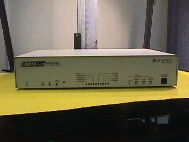
Click to zoom
Application Details
- Equipment Class
- DSS - Part 15 Spread Spectrum Transmitter
- Date of Grant
- Jul 11, 2000
- Application Purpose
- Original Equipment
- Date of Application
- Jan 24, 2000
- Equipment Note
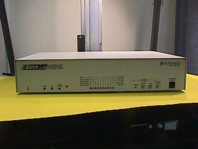
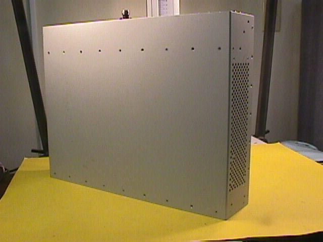
- Spread Spectrum Radio
- Frequency Range
- 2408.00000000 - 2467.00000000
- Company
- Proxim Wireless Corporation
- Country
- United States
Documents & Files
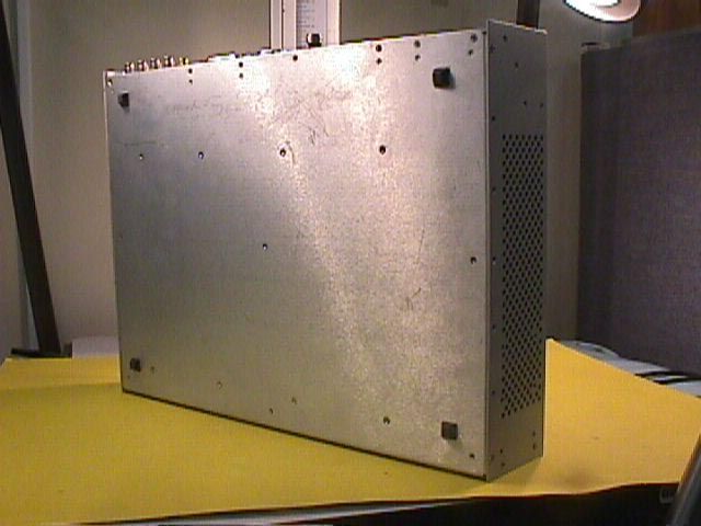
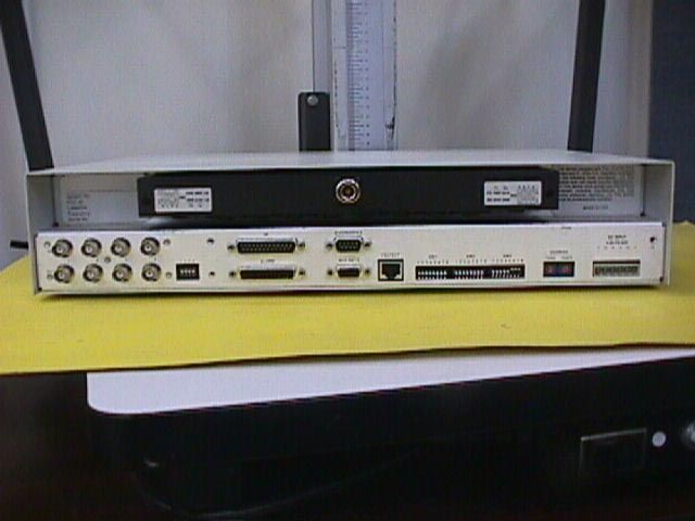
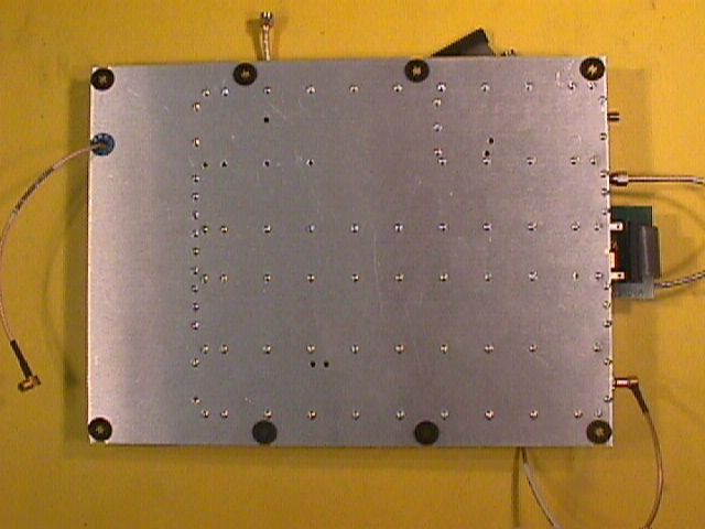
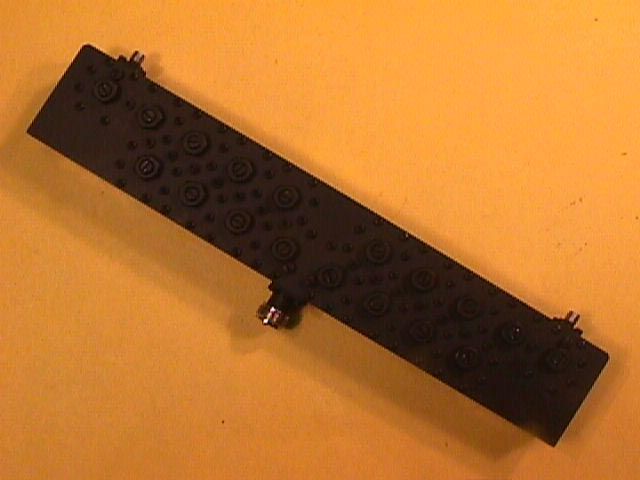
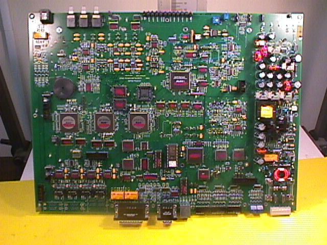
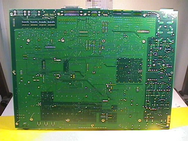
Document Text
Text extracted from the exhibit documents filed with the FCC. Open a document above to read the original.
Users Manual
INSTALLATION AND MAINTENANCE MANUAL 1xE1, 2xE1 AND 4xE1 (2.048 Mbps) SPREAD SPRECTRUM RADIOS (2.4 AND 5.8 GHz) INSTALLATION AND MAINTENANCE MANUAL LYNX.sc E1 FAMILY SPREAD SPECTRUM RADIOS NOVEMBER 1999 i Installation and Maintenance Manual Copyright © 1998 by Western Multiplex Corporation. All rights reserved. No part of this manual may be reproduced without prior written permission from Western Multiplex Corp. The information contained in this manual is subject to change without notice. Western Multiplex shall not be liable for errors contained herein or for incidental or consequential damages in connection with the furnishing, performance, or use of this manual or equipment supplied with this manual. Western Multiplex makes no warranty of any kind with regard to this manual or any equipment supplied with this manual, including, but not limited to, the implied warranties of merchantability and fitness for a particular purpose. Heliax is a registered product of Andrews Corporation. Fireberd is a registered product of Telecommunications Techniques Corporation. Printed in the United States of America Notice: Y2K (Year 2000 Issue) All software supplied by and for Western Multiplex products adheres to the four-(4) digit year nomenclature as required for Year 2000 compliance. Western Multiplex Corporation 1196 Borregas Avenue Sunnyvale, California USA Tel:+1 408 542-5200 Fax::+1 408 542-5300 Our facility has been Registered to the International Organization for Standardization ISO 9000 Series Standards for quality. Issue:November 1999 INSTALLATION AND MAINTENANCE MANUAL LYNX.sc E1 FAMILY SPREAD SPECTRUM RADIOS NOVEMBER 1999 ii This page intentionally left blank INSTALLATION AND MAINTENANCE MANUAL LYNX.sc E1 FAMILY SPREAD SPECTRUM RADIOS NOVEMBER 1999 iii Regulatory Notice This equipment has been tested and found to comply with the limits for a class B digital device, pursuant to Part 15 of the FCC Rules. These limits are designed to provide reasonable protection against harmful interference in a residential installation. This equipment generates, uses and can radiate radio frequency energy and, if not installed and used in accordance with the instructions, may cause harmful interference to radio communications. However, there is no guarantee that interference will not occur in a particular installation. If this equipment does cause harmful interference to radio or television reception, which can be determined by turning the equipment off and on, the user is encouraged to try to correct the interference by one or more of the following measures: *Reorient or relocate the receiving antenna. *Increase the separation between the equipment and receiver. *Connect the equipment into an outlet on a circuit different from that to which the receiver is connected. *Consult the dealer or an experienced radio/TV technician for help. Shielded cables and I/O cords must be used for this equipment to comply with the relevant FCC regulations. Changes or modifications not expressly approved in writing by Western Multiplex may void the user's authority to operate this equipment. This device complies with RSS-210 and/or RSS-139 of Industry Canada. Operation is subject to the following two conditions: (1) this device may not cause interference, and (2) this device must accept any interference, including interference that may cause undesired operation of the device. This device must be professionally installed. INSTALLATION AND MAINTENANCE MANUAL LYNX.sc E1 FAMILY SPREAD SPECTRUM RADIOS NOVEMBER 1999 iv This page intentionally left blank INSTALLATION AND MAINTENANCE MANUAL LYNX.sc E1 FAMILY SPREAD SPECTRUM RADIOS NOVEMBER 1999 vW/CS97-1 GENERAL TERMS 1.1 All Definitions contained in Western Multiplex's Conditions of Sale (Western Multiplex document number CS96-8), apply to the Warranty. 1.2 Subject to the provisions of the Warranty, Western Multiplex warrants that the equipment described in Paragraph 1.3 shall conform to their specifications described in Paragraph 1.4 in all material respects and that the equipment shall be free from material defects in materials and workmanship. 1.3 This Warranty applies to all original purchases of Western Multiplex manufactured equipment and accessories (collectively the "Equipment"). 1.4 This Warranty applies to the specifications contained in the most recent version of the manual for the model of the Equipment purchased (the "Specifications"). 1.5 This Warranty does not apply to the following items of Equipment which are covered by the Original Equipment Manufacturer's warranty: (a) antenna systems, including coax cable, waveguide, connectors flex-sections, mounts, other parts of the antenna system and installation materials; (b) non-Western Multiplex manufactured rack mounted equipment that is assembled wired and tested at Western Multiplex's factory or supplied as part of a system, including orderwire items, channel banks, multiplexers, fuse/alarm panels, remote alarm items; and (c) equipment which is not listed in Western Multiplex's price book. 1.6 The effective period of this Warranty shall start on the date of shipment of the Equipment and shall end: (a) for all spread spectrum unlicensed radio products and for all licensed digital microwave radio products, two (2) years later; (b) for all analog microwave radio products, three (3) years later; or (c) for all baseband products, five (5) years later (in each case the "Warranty Period"). 1.7 The Customer acknowledges that Western Multiplex does not represent or warrant that the services provided by Western Multiplex under this Warranty will ensure uninterrupted or error- free operation of the Equipment. RETURN OF EQUIPMENT UNDER WARRANTY 2.1If an item of Equipment malfunctions or fails in normal intended usage and maintenance within the applicable Warranty Period: (a) the Customer shall promptly notify Western Multiplex of the problem and the serial number of the defective item; (b) Western Multiplex shall, at its sole opt…
Text truncated - open the document above for the full version.
Cover Letter(s)
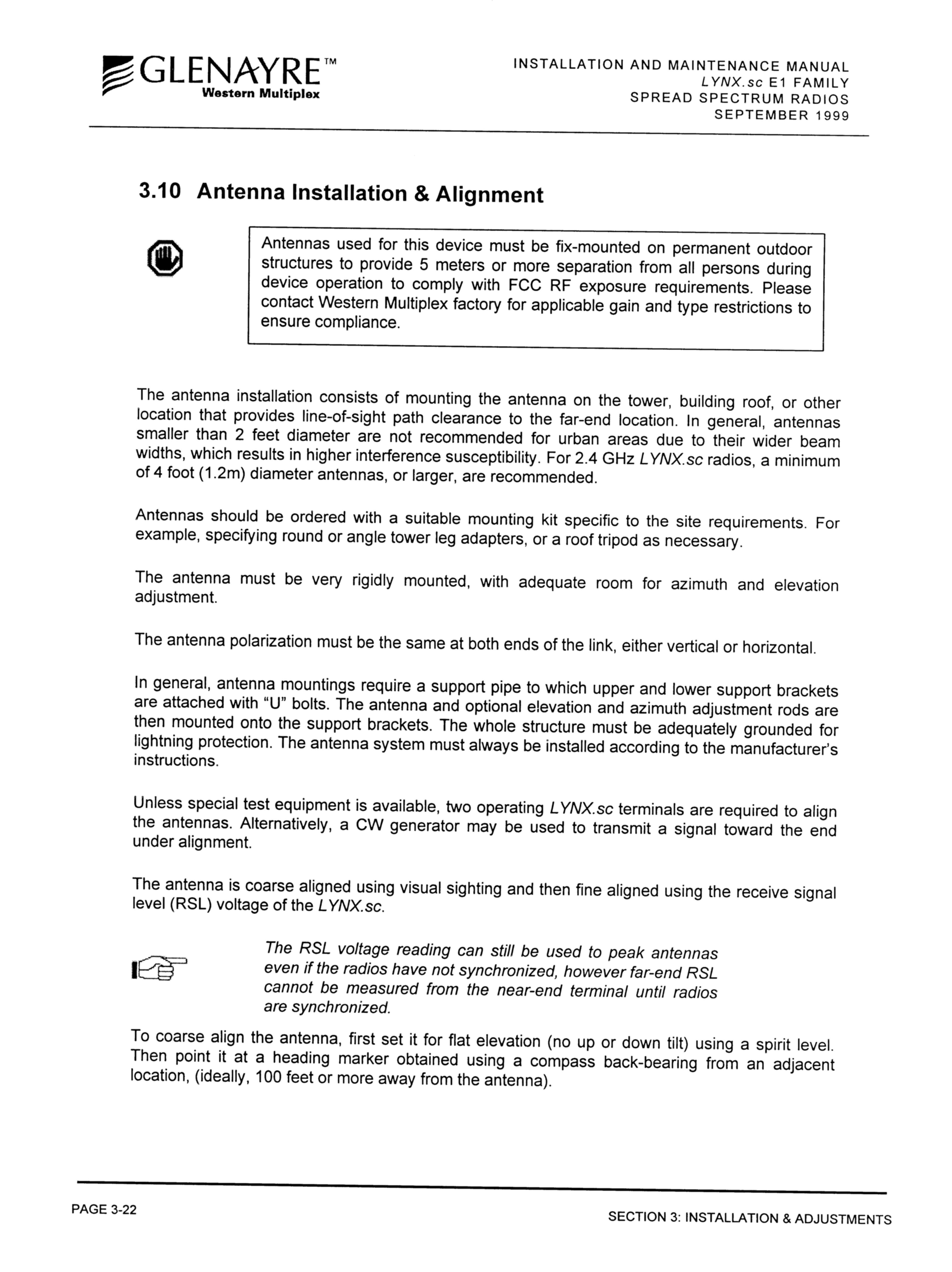
Federal Communications Commission Authorization and Evaluation Division 7435 Oakland Mills Road Columbia, MD 21046 February 18, 2000 Attention: Reviewing Engineer RE: Pro duct Installat io n a nd Mai nte na nce Ma nua l U pdate for H ZB-S24-08 After the application for HZB-S24-08 was submitted to FCC, we updated our product manual to comply with FCC requirements raised while a previous application was in review. Since our LYNX.sc Installation and Maintenance manual covers the whole spread spectrum LYNX.sc product line, these changes applies to the product manual submitted for this application as well. Please find in the attached an updated page of page 3-22 for section 3.10. Please use this page to replace the same page of the submitted manual. Yours tr ul y, Caroline Yu Inter natio nal Product Ma na ger Western Multiplex Corporation 1196 Borregas Ave., Sunnyvale, CA 94089-1302, USA Tel: +1 (408) 542-5200,Fax: +1 (408) 542-5300
Cover Letter(s)
Federal Communications Commission Authorization and Evaluation Division 7435 Oakland Mills Road Columbia, MD 21046 May 3, 2000 RE:Response to FCC Requests Correspondence Reference Numbers: 12911 FCC IDs: HZB-S24-08 Form 731 Confirmation Numbers: EA96599 Attn:Errol Chang Dear Mr. Chang: This is in response to your request 12911 regarding the application of HZB-S24-08 product. In our product manual, we recommend antennas to be used with our equipment by their size and gain. At 2.4GHz band, we recommend 2’ panel antennas and 2’-8’ parabolic antennas. The gains of these antennas range from 27dBi to 33.5dBi. As examples, we recommend to our users some typical antenna vendors now in the market, such Gabriel, Radio Waves, Andrew, Comsat, etc. Though of different make, antennas of the same dimensions have very similar gains and other specifications. The gains of antennas of various sizes are as in the following table. Antenna Type and SizeRange of Mid Band Gain for Antennas by Various Vendors (dBi) 2’ flat panel21.7 2’ parabolic20.6-21.6 4’ parabolic26.6-27.6 6’ parabolic30.1-31.1 8’ parabolic31.8-33.6 We believe as long as the antennas are consistent in their technical specifications, the differences in brand name, model number, and type should not cause discernable differences in radiated emission and RF exposure. We hope when grant conditions are necessary, these conditions will be made in the form of specifications (for example, size, gain range, or EIRP) rather than in the form of model names and vendors. I hope I have addressed questions in your request. Please contact the undersigned should there be any further questions. Yours Caroline Yu International Product Manager Western Multiplex Corporation 1196 Borregas Ave., Sunnyvale, CA 94089-1302, USA Tel: +1 (408) 542-5200,Fax: +1 (408) 542-5300
Cover Letter(s)
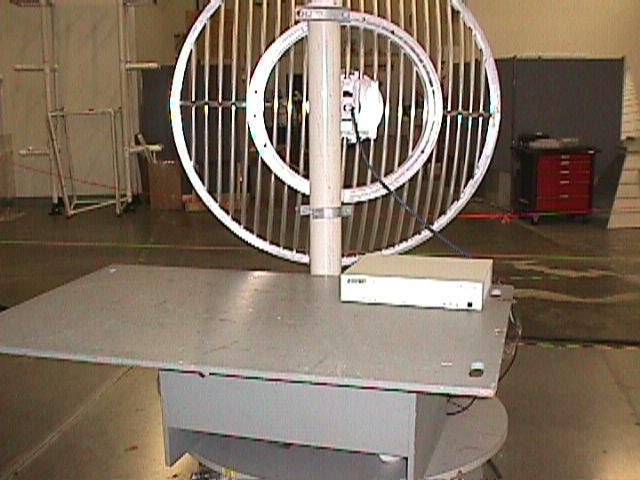
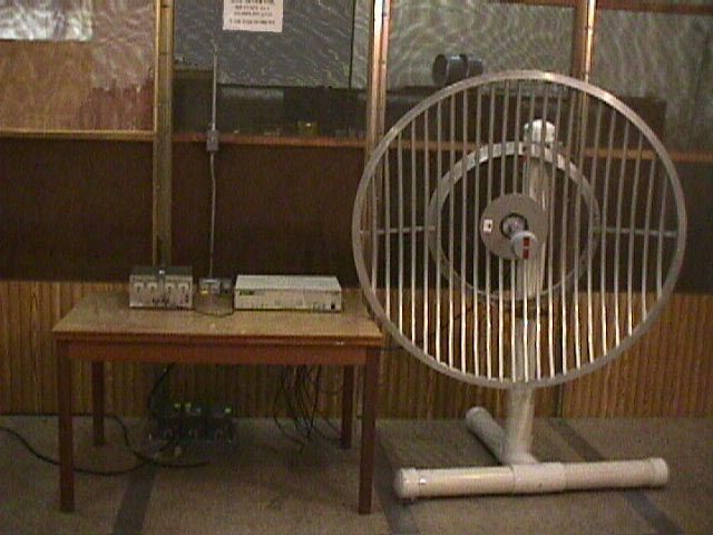
Federal Communications Commission Authorization and Evaluation Division 7435 Oakland Mills Road Columbia, MD 21046 July 5, 2000 RE:Response to FCC Requests Correspondence Reference Numbers: 13858, 14162 FCC IDs: HZB-S24-08 Form 731 Confirmation Numbers: EA96599 Attn:Errol Chang Dear Mr. Chang: This is in response to your request 13858 and 14162 regarding the application of HZB-S24-08 product. 1. The antenna used during testing was a 4-foot grid antenna, Comsat RSI Mark part number P- 24A48G. The gain listed in the report is 27.7 dBi. Please find in attachment 1 the specifications of the antenna. At the time of equipment testing, we were not aware that our equipment needs to be tested separately with a panel antenna. Prior to that point in time, we were able to certify equipment for a range of panel and parabolic antennas by testing with the 4’ grid antenna only. It was not until more recently that the Commission has imposed additional antenna testing on our products. Given the timing of this testing, we request that the Commission permit the use of panel antennas up to 2’ in size without additional testing. Note that the 2’ flat panel antenna specifications are by no means worse in any respect than that of the 4’ parabolic antenna that was used during testing. 2. We request that the HZB-S24-08 radio be allowed to operate with up to 8’ antennas. There are several needs/benefits of using a higher gain antenna. First, a higher gain antenna has narrower beamwidth, which allows better frequency reuse and less interference. Also, in situations of considerable RF cable loss, additional antenna gain may be needed to compensate the cable loss. Occasionally, there are cases where a customer already has antennas of this size in use, and we like to allow them to use these existing antennas. We feel that these customers should be able to take advantage of the existing antennas by using the radio under a reduced output power, rather than having to invest in new antennas. We recognize the fact that the radio was tested with a 4’ antenna of 27.7 dBi gain. We suggest that the best solution is for the Commission to limit the EIRP for this system to that of the tested EIRP of 50.5 dBm. We will include information in our manual to instruct the customers how to properly adjust the output power to ensure that the tested EIRP is not exceeded. Please see in the attachment 2 for the information we shall include in page 3-19 of the manual. Please note, that even with 8’ antennas, in some cases where there is considerable cable loss, the tested EIRP will not be reached and the narrow beamwidth of the antenna is considerably beneficial to spectrum sharing. 1196 Borregas Ave., Sunnyvale, CA 94089-1302, USA Tel: +1 (408) 542-5200,Fax: +1 (408) 542-5300 3. Please find in the following table detailed information of some antennas we recommend as examples. Since there are numerous antenna manufacturers and product models in the market, this is only a partial list. Antenna TypeManufacturerModel NumberMid-band Gain (dBi) 2 foot ParabolicGabriel ElectronicsSSP2-2320.7 3 foot ParabolicGabriel ElectronicsSSG3-23A23.9 4 foot ParabolicAndrewFP4-23D26.5 4 foot ParabolicGabriel ElectronicsSSG4-23A26.7 6 foot ParabolicAndrewFP6-23D30.4 6 foot ParabolicGabriel ElectronicsSSG6-23A30.1 8 foot ParabolicAndrewFP8-23D32.7 8 foot ParabolicGabriel ElectronicsSSG8-2332.6 I hope I have addressed your concerns. Please contact the undersigned should there be any further questions. Yours truly Caroline Yu International Product Manager Western Multiplex Corporation INSTALLATION AND MAINTENANCE MANUAL LYNX.sc E1 FAMILY SPREAD SPECTRUM RADIOS SEPTEMBER 1999 SECTION 3: INSTALLATION & ADJUSTMENTSPAGE 3-39 3.13.1 Output Power Adjustment The LYNX.sc radio requires professional installation. In certain cases, it is necessary to adjust the output power from the factory setting, for example: vto meet EIRP (effective isotropic radiated power) limits, such as +6 dBW in Canada. vto meet transmitter output limits in the 2.4 GHz band for USA installations. vto avoid exceeding the maximum far-end RSL of 0 dBm. vto coordinate a hub or repeater location. To ensure maximum protection of the radio circuits, always ensure the antenna connector is terminated when power is applied. For precise measurement of transmitter power, a calibrated RF power meter (such as the HP 435B with Power Sensor HP8481) is recommended. This power sensor can be connected directly to the output of the radio without exceeding the power rating. With some power meters, it may be necessary to place a calibrated in-line fixed attenuator between the radio antenna port and the power meter so as to not exceed the power meter’s maximum input level. Thruline power meters do not operate at LYNX.sc RF frequencies. If adjusting the output power to meet an EIRP limit, it will be first necessary to calculate the overall system gains and losses, including feeder losses for the type of transmission line installed and the antenna gain. Also refer to Table 3-C or 3-D for transmitter output power settings where installed with various transmission line lengths and antenna sizes. You may determine the radio transmit power for EIRP limited installations by the following equation: Tx Power (dBm) = EIRP Limit(dBm) + Feeder Loss(dB) - Antenna Gain(dB) In the USA, 2.4 GHz models have an output limit which is determined by: Tx Power (dBm) = 30 - [(Antenna Gain - 6)/ 3] + Feeder Loss (Note: For the LYNX.sc2 4xE1 model, the transmit power should be the lesser of Tx Power as calculated above or [50.3-Antenna Gain + Feeder Loss] ) Output power may be adjusted using a small screwdriver and rotating the potentiometer which is recessed behind the front panel. Clockwise rotation increases output power while counter-clockwise rotation decreases output power. In lieu of a calibrated RF power meter, the PWR test port voltage can be used to estimate the output power. Figures 3-16 & 3-17 illustrate the voltage reading for vario…
Text truncated - open the document above for the full version.
RF Exposure Info
Federal Communications Commission Authorization and Evaluation Division 7435 Oakland Mills Road Columbia, MD 21046 Attention: Reviewing Engineer The HZB-S24-08 (MODEL 31350) radio is a full duty-cycle product exclusively designed for fixed-mount point-to-point applications (Please refer to Page 1-1 of the Installation and Maintenance Manual ). Each radio’s inputs are connected to external equipment through the radio’s interfaces. The RF output port is connected to a RF cable or a waveguide, which connects on the other side to an antenna usually installed on top of a building or a tower. It is impossible to use the radio in any mobile application. The HZB-S24-08 (MODEL 31350) radios need to be professionally installed outdoor either on top of a tower or a tall building. The installation sites are inaccessible to the general public. Only installation engineers may get close to the radio antenna during system installation. For the safety concern of the professional installers, we put a warning message on Page 3-22 of the product manual recommending installers stay at least 5 meters away from the antenna during system operation. The maximum output power allowed for the 2.4GHz spread spectrum radios is 1W, and the biggest antenna to be used with our 2.4GHz radios is of 8’ diameter (33.5dB gain). The worst case EIRP is when the highest gain antenna is used: Maximum EIRP = 30 + 33.5 – (33.5-6)/3 = 54.3dBm (269W); The power density at 5 meters from an antenna is: S = EIRP/4 π R 2 = 0.9 W/m 2 = 0.09 mW/cm 2 < 1 mW/cm 2 Where: S = Power density R = distance to the center of radiation of the antenna In the cases of using 4’, 6’ and 8’ parabolic antennas, the near field power density is S nf = 16 η P/ π D 2 . The worst case of near-field power density is when the radio output at 1W, η =1, and the antenna diameter D=4ft. S nf ma x = 16 x1/ π (4x0.3048) 2 = = 3.4 W/m 2 = 0.34 mW/cm 2 <1 mW/cm 2 Where: S nf = maximum near –field power density P = power fed to the antenna η = aperture efficiency D = antenna diameter So in all the above-mentioned situations, the power density is compliant with the limit for General Population/ Uncontrolled Exposure as specified in rule 1.1310. If you should have any questions regarding this submission, please feel free to contact the undersigned. Yours tr ul y, Caroline Yu Inter natio nal Product Ma na ger Western Multiplex Corporation 1196 Borregas Ave., Sunnyvale, CA 94089-1302, USA Tel: +1 (408) 542-5200,Fax: +1 (408) 542-5300
RF Exposure Info
Federal Communications Commission Authorization and Evaluation Division 7435 Oakland Mills Road Columbia, MD 21046 July 5, 2000 RE:Response to FCC Requests Correspondence Reference Numbers: 13858, 14162 FCC IDs: HZB-S24-08 Form 731 Confirmation Numbers: EA96599 Attn:Errol Chang Dear Mr. Chang: This is in response to your request 13858 and 14162 regarding the application of HZB-S24-08 product. 1. The antenna used during testing was a 4-foot grid antenna, Comsat RSI Mark part number P- 24A48G. The gain listed in the report is 27.7 dBi. Please find in attachment 1 the specifications of the antenna. At the time of equipment testing, we were not aware that our equipment needs to be tested separately with a panel antenna. Prior to that point in time, we were able to certify equipment for a range of panel and parabolic antennas by testing with the 4’ grid antenna only. It was not until more recently that the Commission has imposed additional antenna testing on our products. Given the timing of this testing, we request that the Commission permit the use of panel antennas up to 2’ in size without additional testing. Note that the 2’ flat panel antenna specifications are by no means worse in any respect than that of the 4’ parabolic antenna that was used during testing. 2. We request that the HZB-S24-08 radio be allowed to operate with up to 8’ antennas. There are several needs/benefits of using a higher gain antenna. First, a higher gain antenna has narrower beamwidth, which allows better frequency reuse and less interference. Also, in situations of considerable RF cable loss, additional antenna gain may be needed to compensate the cable loss. Occasionally, there are cases where a customer already has antennas of this size in use, and we like to allow them to use these existing antennas. We feel that these customers should be able to take advantage of the existing antennas by using the radio under a reduced output power, rather than having to invest in new antennas. We recognize the fact that the radio was tested with a 4’ antenna of 27.7 dBi gain. We suggest that the best solution is for the Commission to limit the EIRP for this system to that of the tested EIRP of 50.5 dBm. We will include information in our manual to instruct the customers how to properly adjust the output power to ensure that the tested EIRP is not exceeded. Please see in the attachment 2 for the information we shall include in page 3-19 of the manual. Please note, that even with 8’ antennas, in some cases where there is considerable cable loss, the tested EIRP will not be reached and the narrow beamwidth of the antenna is considerably beneficial to spectrum sharing. 1196 Borregas Ave., Sunnyvale, CA 94089-1302, USA Tel: +1 (408) 542-5200,Fax: +1 (408) 542-5300 3. Please find in the following table detailed information of some antennas we recommend as examples. Since there are numerous antenna manufacturers and product models in the market, this is only a partial list. Antenna TypeManufacturerModel NumberMid-band Gain (dBi) 2 foot ParabolicGabriel ElectronicsSSP2-2320.7 3 foot ParabolicGabriel ElectronicsSSG3-23A23.9 4 foot ParabolicAndrewFP4-23D26.5 4 foot ParabolicGabriel ElectronicsSSG4-23A26.7 6 foot ParabolicAndrewFP6-23D30.4 6 foot ParabolicGabriel ElectronicsSSG6-23A30.1 8 foot ParabolicAndrewFP8-23D32.7 8 foot ParabolicGabriel ElectronicsSSG8-2332.6 I hope I have addressed your concerns. Please contact the undersigned should there be any further questions. Yours truly Caroline Yu International Product Manager Western Multiplex Corporation INSTALLATION AND MAINTENANCE MANUAL LYNX.sc E1 FAMILY SPREAD SPECTRUM RADIOS SEPTEMBER 1999 SECTION 3: INSTALLATION & ADJUSTMENTSPAGE 3-39 3.13.1 Output Power Adjustment The LYNX.sc radio requires professional installation. In certain cases, it is necessary to adjust the output power from the factory setting, for example: vto meet EIRP (effective isotropic radiated power) limits, such as +6 dBW in Canada. vto meet transmitter output limits in the 2.4 GHz band for USA installations. vto avoid exceeding the maximum far-end RSL of 0 dBm. vto coordinate a hub or repeater location. To ensure maximum protection of the radio circuits, always ensure the antenna connector is terminated when power is applied. For precise measurement of transmitter power, a calibrated RF power meter (such as the HP 435B with Power Sensor HP8481) is recommended. This power sensor can be connected directly to the output of the radio without exceeding the power rating. With some power meters, it may be necessary to place a calibrated in-line fixed attenuator between the radio antenna port and the power meter so as to not exceed the power meter’s maximum input level. Thruline power meters do not operate at LYNX.sc RF frequencies. If adjusting the output power to meet an EIRP limit, it will be first necessary to calculate the overall system gains and losses, including feeder losses for the type of transmission line installed and the antenna gain. Also refer to Table 3-C or 3-D for transmitter output power settings where installed with various transmission line lengths and antenna sizes. You may determine the radio transmit power for EIRP limited installations by the following equation: Tx Power (dBm) = EIRP Limit(dBm) + Feeder Loss(dB) - Antenna Gain(dB) In the USA, 2.4 GHz models have an output limit which is determined by: Tx Power (dBm) = 30 - [(Antenna Gain - 6)/ 3] + Feeder Loss (Note: For the LYNX.sc2 4xE1 model, the transmit power should be the lesser of Tx Power as calculated above or [50.3-Antenna Gain + Feeder Loss] ) Output power may be adjusted using a small screwdriver and rotating the potentiometer which is recessed behind the front panel. Clockwise rotation increases output power while counter-clockwise rotation decreases output power. In lieu of a calibrated RF power meter, the PWR test port voltage can be used to estimate the output power. Figures 3-16 & 3-17 illustrate the voltage reading for vario…
Text truncated - open the document above for the full version.
Contact Information
Applicant
Ken Lim(Accounting Manager)
Technical Contact
Intertek Testing ServicesDavid Chernomordik
[email protected]650/463-2900
1365 Adams Ct. · Menlo Park, California · United States
Non-Technical Contact
Western Mulitplex CorporationCaroline Yu
[email protected]408/542-5200
Technical Specifications
| # | Rule Parts | Frequency Range | Power Output |
|---|---|---|---|
| 1 | 15C | 2.41 GHz - 2.47 GHz | 190.00 mW |
Other Applications from Proxim Wireless Corporation
HZB-MEGA6
Aug 12, 2026EdgeAX 6GHz Radio Module
Equipment Class
6FC - 15E 6 GHz Fixed Client
HZB-GIGA5
Sep 21, 2023Startum X5 Gigabit 5 GHz Radio
Equipment Class
NII - Unlicensed National Information Infrastructure TX
HZB-NGPAP
Apr 26, 2021NGP LC 2.4 & 5 GHz Radios
Equipment Class
NII - Unlicensed National Information Infrastructure TX
HZB-NGPLC
Mar 04, 2021NGP LC 5 GHz Radio
Equipment Class
DTS - Digital Transmission System
HZB-NGP1058W
Nov 03, 2015802.11 ac PCIe Module
Equipment Class
DTS - Digital Transmission System