HZB-S58-S60CUnlicensed Spread Spectrum Transceiver
Proxim Wireless Corporation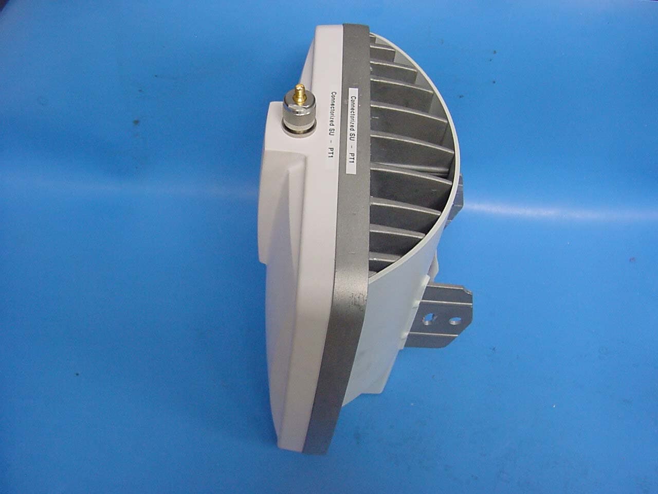
Click to zoom
Application Details
- Equipment Class
- DTS - Digital Transmission System
- Date of Grant
- Apr 02, 2003
- Application Purpose
- Original Equipment
- Date of Application
- Mar 30, 2003
- Equipment Note
- Unlicensed Spread Spectrum Transceiver
- Frequency Range
- 5740.00000000 - 5810.00000000
- Company
- Proxim Wireless Corporation
- Country
- United States
Documents & Files
Document Text
Text extracted from the exhibit documents filed with the FCC. Open a document above to read the original.
Users Manual
Connecting External Antennas TSUNAMI MULTIPOINT CPN required Issue Date: 03/05/2003 Copyright and Service Marks Copyright © 2002 by Proxim Corporation. All rights reserved. No part of this manual may be reproduced without prior written permission from Proxim Corporation. The information contained in this manual is subject to change without notice. Proxim Corporation shall not be liable for errors contained herein or for incidental or consequential damages in connection with the furnishing, performance, or use of this manual or equipment supplied with this manual. Proxim Corporation makes no warranty of any kind with regard to this manual or any equipment supplied with this manual, including, but not limited to, the implied warranties of merchantability and fitness for a particular purpose. Tsunami™ is a registered product of Proxim Corporation. Windows is a registered product of Microsoft Inc. Other names are trademarks of their owners. Y2K (Year 2000 Issue): All software supplied by and for Proxim Corporation products adhere to the four- (4) digit year nomenclature as required for Year 2000 compliance. Contents CONNECTING EXTERNAL ANTENNAS TO THE BSU AND SU...................................................4 Planning for Antenna Installation.......................................................................................4 Reviewing the Installation Process.....................................................................................6 1. Test radios back-to-back and configure.................................................................... 6 2. Mount antennas...................................................................................................6 3. Run transmission line route and egress, including lightning arrestors...........................6 4. Connect radios to antennas and power, including grounding.......................................7 5. Align antennas.....................................................................................................7 Installing the Units......................................................................................................... 78 9 9 11 Establishing Connections..................................................................................................8 Antenna Connection...................................................................................................8 Antenna Cabling Guidelines for 5.8 GHz Units................................................................ 8 BSU/SU RF Connections............................................................................................. 8 BSU/SU Power Connections........................................................................................10 Installing and Adjusting the Antenna.................................................................................10 Antenna Installation..................................................................................................10 Alignment Guidelines............................................................................................. 10 Establishing a Connection Between the Units......................................................................12 Connecting External Antennas to the BSU and SU 3 CPN 000000 Draft Date: 02/25/03 Connecting External Antennas to the BSU and SU Standard Tsunami Multipoint outdoor unit models include integral antennas. However, SU models 40100-xxxC and BSU models 40400-xxC replace the integral antennas with a type-N female connector, letting you purchase and use antennas better suited for your particular application, if so desired. Planning for Antenna Installation In general, the larger the antenna used with the radio, the better the link performs. Larger antennas have narrower beamwidth and higher gain, which yield better link performance (higher fade margin, better availability) and improve immunity to interference. However, larger antennas are more costly to purchase and install than smaller antennas and, in some cases, require special installation equipment and more robust mounting structures (due to increased weight and wind loading). Base stations, however, require wide beamwidths in azimuth so that a large segment of subscribers can be accessed spatially. Antennas are available to allow sectors ranging from 30° to 360°. Of course, the larger the sector, the less antenna gain for longer transmission distance and interference immunity. Finally, antenna polarization must be considered. The BSU and SU integral antennas use left-hand circular polarization (LHCP). External antennas with either linear or circular polarization can be considered. Use the following guidelines to assist in your planning. 1. The polarization of the BSU and SU antennas should be of the same type. For a given polarization, the same polarity (vertical ir horizontal) must be used at each end of the link. 2. Linear and circular polarization can be used at opposite ends of the link; however, this results in a 3 dB loss in signal strength. 3. Integral antenna units and external antenna units can be used in the same sector. 4. Only LHCP antennas can be used with SUs connecting to a BSU with Active Interference Rejection (A.I.R.). Note: The A.I.R. BSU is compatible only with LHCP signals from SUs. SUs must use LHCP antennas; either the integral antenna or an LHCP external antenna. You should consider all of these factors when selecting an antenna. This advanced planning also yields the transmission line requirements. 4 Connecting External Antennas to the BSU and SU Draft Date: 02/25/03 CPN 000000 The following tables list antenna types, performance, and manufacturers. BSU Antenna Information Antenna Type Manufacturer Model Number Mid-Band Gain (dBi) Omni Telex MTI MTI 5830AN MT-482009/N MT-483003/N 7.5 9 12 Flat Panel, Sector European Antennas European Antennas Radio Waves Radio Waves SA16-30-58H/736 SA17-55V/450 SEC-5V/H-90-17 SEC-5V/H-60-18 16 17 17 18 SU Antenna Informati…
Text truncated - open the document above for the full version.
Users Manual
Tsunami Multipoint Version 1.3 Installation Manual CPN 63179 Issue Date: 01/24/03 Copyright and Service Marks Copyright © 2002 by Proxim Corporation. All rights reserved. No part of this manual may be reproduced without prior written permission from Proxim Corporation. The information contained in this manual is subject to change without notice. Proxim Corporation shall not be liable for errors contained herein or for incidental or consequential damages in connection with the furnishing, performance, or use of this manual or equipment supplied with this manual. Proxim Corporation makes no warranty of any kind with regard to this manual or any equipment supplied with this manual, including, but not limited to, the implied warranties of merchantability and fitness for a particular purpose. Tsunami™ is a registered product of Proxim Corporation. Windows is a registered product of Microsoft Inc. Other names are trademarks of their owners. Y2K (Year 2000 Issue): All software supplied by and for Proxim Corporation products adhere to the four- (4) digit year nomenclature as required for Year 2000 compliance. Regulatory Notice This equipment has been tested and found to comply with the limits for a class B digital device, pursuant to Part 15 of the FCC Rules. These limits are designed to provide reasonable protection against harmful interference in a residential installation. This equipment generates, uses and can radiate radio frequency energy and, if not installed and used in accordance with the instructions, may cause harmful interference to radio communications. However, there is no guarantee that interference will not occur in a particular installation. If this equipment does cause harmful interference to radio or television reception, which can be determined by turning the equipment off and on, the user is encouraged to try to correct the interference by one or more of the following measures: Reorient or relocate the receiving antenna. Increase the separation between the equipment and receiver. Connect the equipment into an outlet on a circuit different from that to which the receiver is connected. Consult the dealer or an experienced radio/TV technician for help. Shielded cables and I/O cords must be used for this equipment to comply with the relevant FCC regulations. Changes or modifications not expressly approved in writing by Proxim Corporation may void the user's authority to operate this equipment. This device complies with RSS-210 of Industry Canada. Operation is subject to the following two conditions: (1) this device may not cause interference, and (2) this device must accept any interference, including interference that may cause undesired operation of the device. WARNING! This device must be professionally installed! Tsunami Multipoint Version 1.3 Installation Guide Contents ABOUT THIS BOOK...............................................................................................................5 Required Software and Firmware........................................................................................5 Safety Instructions...........................................................................................................6 CHAPTER 1. SITE PLANNING...............................................................................................7 General Considerations.....................................................................................................7 Specific Considerations.....................................................................................................8 Interference and How to Avoid It......................................................................................10 Antennas......................................................................................................................11 Path Planning................................................................................................................14 PMP Radio Information...................................................................................................14 CHAPTER 2. DEPLOYING THE BASE STATION UNIT (BSU)..................................................16 Unpacking the System....................................................................................................16 Mounting the Base Station Unit........................................................................................17 Installing the GPS Antenna..............................................................................................24 Installing BSU Configuration Software...............................................................................25 CHAPTER 3. DEPLOYING THE SUBSCRIBER UNIT...............................................................31 Mounting the Subscriber Unit (SU)...................................................................................31 Installing the Subscriber Utility Software...........................................................................34 Aiming the SU...............................................................................................................35 Displaying Link Status Information...................................................................................36 Confirming Network Activity............................................................................................38 CHAPTER 4. SYSTEM DIAGNOSTICS AND OPERATING TIPS...............................................40 Radio Diagnostics........................................................................................................... 40 Network Configuration Tips.............................................................................................44 Protecting the System....................................................................................................45 APPENDIX A. INITIAL SETTINGS.......................................................................................49 Specify the Desired Modu…
Text truncated - open the document above for the full version.
Users Manual
Tsunami Multipoint Version 1.3 Installation Guide Figure 7. BSU Mounting Hardware Required Tools: 9/16” (14-23 mm) wrench 6” (155 mm) crescent wrench Note: Torque all #3/8 bolts and nuts 250 ± 10 in-lbs. BSU Mounting: Ground Work To assemble the BSU’s mounting components: 1. Place the BSU face (transmitter side) down on a flat surface. 2. Attach the two (u-shaped) galvanized mounting brackets to the back of the BSU using the four stainless steel 3/8-16, hex head screws and four #3/8 split lock washers (see the following photo). Figure 8. U-Shaped Mounting Brackets Attached 3. Insert two 1/2-13x7 1/2 screws through one of the clamp brackets (m-shaped) and secure the bolts using two 1/2-13 hex nuts. Repeat this step for the other set of 1/2-13x7 1/2 screws, clamp bracket, and 1/2-13 hex nuts (see Figure 9). Chapter 2. Pre-Installation Tasks 18 CPN 63179 Issue Date: 01/24/03 Tsunami Multipoint Version 1.3 Installation Guide 4. Connect the downtilt bracket to the notched bracket using two 3/8-16x1 1/4 hex head screws, #3/8 split lock washers, #3/8 (star) lock washers, and 3/8-16 hex nuts (see Figure 9). Figure 9. Downtilt and Clamp Brackets with Screws Attached Figure 10. Bracket Assembly Detail of Screw, Washers, and Nut 5. Attach the downtilt/notched bracket assembly to the u-shaped mounting bracket near the middle of the BSU using two sets of 3/8-16x1 1/4 hex head screws, #3/8 split lock washers, and 3/8-16 nuts. Note: This mounting method lets you point the BSU down when mounted on a pole; to point the BSU up, attach the downtilt/notched bracket assembly to the u-shaped mounting bracket near the bottom of the BSU. Chapter 2. Pre-Installation Tasks 19 CPN 63179 Issue Date: 01/24/03 Tsunami Multipoint Version 1.3 Installation Guide Figure 11. Bracket Assembly Attached to Mounting Bracket 6. Attach one of the 1/2-13x7 1/2 screws/clamp bracket assemblies to the u-shaped mounting bracket near the end of the BSU using two sets of 3/8-16x1 1/4 hex head screws, #3/8 split lock washers, and 3/8-16 hex nuts (see Figure 12). (In this configuration, the BSU points down when mounted on a pole.) 7. Attach the other 1/2-13x7 1/2 screws/clamp bracket assembly to the downtilt bracket using two sets of 3/8-16x1 1/4 hex head screws, #3/8 split lock washers, and 3/8-16 hex nuts (see Figure 12). Figure 12. Screws/Clamp Bracket Assemblies Attached Chapter 2. Pre-Installation Tasks 20 CPN 63179 Issue Date: 01/24/03 Tsunami Multipoint Version 1.3 Installation Guide Mounting the BSU to a Pole To mount the BSU to a pole using the attached mounting components: 1. Lash the unit to the pole or use a hoisting rope to keep the unit in place while you mount it. Slide the two strap clamps over the two sets of 1/2-13x7 1/2 screws and secure the strap clamps using four #1/2 split lock washers and four 1/2-13 hex nuts (see the following photo). Figure 13. Strap Clamps Attached and Mounted BSU 2. To adjust the up/down tilt (-10 to +5 degrees), move the top or bottom of the BSU (depending on how you installed the downtilt/notched bracket assemblies) until the unit is roughly positioned at the correct angle. 3. Connect the supplied Cat 5 cable to the BSU’s Power and Ethernet port as described in the following notes. Then screw on the outer ring to secure the cable in place. Figure 14. BSU’s Power and Ethernet Connector Chapter 2. Pre-Installation Tasks 21 CPN 63179 Issue Date: 01/24/03 Tsunami Multipoint Version 1.3 Installation Guide The Base Station Unit (BSU) is shipped with a dust cover over the large 18-pin connector. Keep this cover on until ready to mate with cable connector to avoid getting the connector wet. To ensure proper weatherproofing, follow these procedures to connect the supplied Cat 5 cable to the BSU’s Power and Ethernet port. A. Check the BSU connector. The only moving part should be the plastic nut (“B”), which screws onto the BSU housing. B. If there is any movement or play between parts A and C, you must tighten these parts before proceeding; otherwise you could cause connector pins to disconnect or break when you apply the weatherproofing tape. To tighten, first loosen (but do not remove) the connector’s screws (indicated with arrows in the previous figure). C. Then, while holding the pin connection portion (1), turn the bottom portion (2) clockwise until there is no more movement, making sure you do not over-tighten. D. Re-tighten the screws. E. When mating the BSU to the cable connector, first apply a bead of silicone grease or RTV to the 3mm-wide outward-most flange on the BSU connector (or in the outer ring of the cable- end mating connector). F. Then tighten the plastic nut on the cable end to 16 inch-lbs (1.81 N-m). The cable connector must be tightened onto the BSU sufficiently to compress a small O-ring that resides inside the male BSU connector. If the O-ring is missing or insufficiently compressed, moisture can get through into the connector pins. Chapter 2. Pre-Installation Tasks 22 CPN 63179 Issue Date: 01/24/03 Tsunami Multipoint Version 1.3 Installation Guide Once mated, over-wrap the connectors (as demonstrated in the following table) with stretchy black self amalgamating tape (such as CTB-15 CATV TAPE-X5-BK-UN part #22150000 from DSG – CANUSA 173, Commerce Boulevard, Loveland, Ohio 45140, Tel. 1-800-422-6872) to ensure a better water seal. 1) 2) 3) 4) 5) 6) 4. Connect the other end of the Cat 5 cable to the BSU’s power supply. (The BSU’s power supply is ordered and shipped separately. The power supply’s CPN number is 58526.) 5. Plug the power supply into an electrical outlet. Note: To ensure proper grounding, use the hole on the back of the BSU and the provided grounding screw to attach a ground wire to the BSU. Use wire grounding techniques in accordance with your local electrical codes. Chapter 2. Pre-Installation Tasks 23 CPN 63179 Issue Date: 01/24/03 Tsunami Multipoint Version 1.3 Installation Guide Installing the GPS Antenna If you do not plan to install multiple BSU in the same …
Text truncated - open the document above for the full version.
Users Manual
Tsunami Multipoint Version 1.3 Installation Guide Frequency Channel Shows the current channel plan/frequency setting (for example, 4C). See “Change the Frequency Plan and Operating Frequency” on page 50 for information. By default, the SU is set to automatically search for the correct frequency channel. Receive Signal Quality (dBm) Shows the quality of signal received by the local SU (in dBm). This value represents the estimated received signal level, plus an offset of 120 dB. A received signal quality level over 40 (which represents a signal level of -80 dBm) shows an acceptable signal quality. º You can use this field to fine tune BSU/SU alignment. After you mount the units outdoors, check the Receive Signal Quality value as you make fine adjustments to the BSU/SU alignment until you obtain optimal signal quality. Transmitter Power Shows the SU’s current transmitter power (-30 to +36). Ethernet Interface Shows the current Ethernet interface setting. If the Ethernet interface was set to auto-netotiate, this entry contains the results of the auto-negotiation. Network Mode Shows the current network mode: Bridging, VPN, or IP Routing. Confirming Network Activity Attempt to ping from a computer connected to: ▪ An SU to the BS (BSU and SU must have different IP addresses to do this. If the BSU and SU are configured with the same IP address, the local unit responds to the ping (that is, if the BSU and SU have the same IP address and you ping the BSU from a host connected to the SU, the SU responds to the ping). ▪ The BSU to the SU. (BSU and SU must have different IP addresses to do this. If the BSU and SU are configured with the same IP address, the local unit responds to the ping (that is, if the BSU and SU have the same IP address and you ping the BSU from a host connected to the SU, the SU responds to the ping). If successful and possible, attempt to ping from a computer on the SU side of the network to a computer on the BSU side of the network. Chapter 3. Deploying the Subscriber Unit (SU) 38 CPN 63179 Issue Date: 01/24/03 Tsunami Multipoint Version 1.3 Installation Guide If the ping tests are unsuccessful, attempt the following: ▪ Check all IP and computer configurations (for example, if you attempt to ping the BSU from the SU configuration computer and the BSU and SU’s are in separate networks you must have the configurations computers gateway set to the SU for the ping to work.) ▪ Adjust the network’s IP settings, if necessary, to achieve IP connectivity. If the above fails refer to “System Diagnostics” to help debug possible link problems. Note: See “Chapter 4. System Diagnostics and Operating Tips” on page 40 for information about running system diagnostics to make sure the equipment is operating as expected . Chapter 3. Deploying the Subscriber Unit (SU) 39 CPN 63179 Issue Date: 01/24/03 Tsunami Multipoint Version 1.3 Installation Guide Chapter 4. System Diagnostics and Operating Tips This section describes several diagnostic tests you can perform once the Tsunami MP equipment is installed. These tests assist you in determining whether the equipment is functioning as expected. In addition, we include some miscellaneous useful information for deploying a Multipoint network. Radio Diagnostics Use the diagnostic tools described in this section to determine if your wireless link is stable. You can also use these tools to help fine-tune antenna positions to establish a good link. BSU and SU Logs You can display BSU and SU logs to help troubleshoot possible link reliability and interference issues. These tools have no impact on data traffic, and can be used in conjunction with configuration parameters (such as IPC settings, modulation modes, and operating frequencies) and possible antenna relocation to obtain the best possible path. The goal is to maximize the Es/N0 ratio. Displaying the BSU Log Follow these steps to enable the BSU log: 1. Enter BSUlog (Terminal ID> <time> where <Terminal ID> is the Terminal ID of the SU to be monitored and <time> specifies the polling period (in seconds). Figure 24. BSU Log in the Base Station Configuration Software 2. When finished, disable the BSU log by entering BSUlog 0 (zero). Chapter 4. System Diagnostics and Operating Tips 40 CPN 63179 Issue Date: 01/24/03 Tsunami Multipoint Version 1.3 Installation Guide Monitor the Es/No ratio (Es/No reports the energy per symbol-to-noise spectral density ratio (in dB)). Low Es/N0 or varying Es/N0 can indicate path or interference problems. The Es/No requirement varies based on the modulation mode: 20 Mbps: Es/No > 4 + IPC value 30 Mbps: Es/No > 5 + IPC value 40 Mbps: Es/No > 9 + IPC value 60 Mbps: Es/No > 12 + IPC value In addition, the BSU log provides the following information: Int Relative interference of the power received at the BSU (a value of 0 (zero) nominally shows no interference) GPS sync -1 indicates GPS sync is disabled; 4 indicates GPS sync is enabled. GPS synchronization is used when the system is in Multi Sector mode (multiple BSUs installed in the same location; see “Configuring the System for Multi-Sector Mode” on page 29 for more information). SU ID The Terminal ID of the monitored SU Time error Shows the uplink (or inbound) ranging error Rx cell error Shows the number of lost uplink cells Rx cells Shows the total number of uplink cells Time Shows the cumulative polling time (in seconds) Displaying the SU Logs You can display two different types of SU logs: SUlog1 and SUlog2. To display the SU logs, install the Base Station Configuration Software on the PC used to configure the SU (see “Installing the Base Station Configuration Software” for information) and then execute the commands described below. Follow these steps to enable an SU log: 1. Enter SUlog1 <time> or SUlog2 <time> where <time> specifies the polling period (in seconds). (Specify SUlog1 to display SUlog1; specify SUlog2 to display SUlog2. See the information below for details about these two logs.) Chapter 4. System Diagnostics a…
Text truncated - open the document above for the full version.
Attestation Statements
935 Stewart Drive, Sunnyvale, CA, USA94085 Tel (408) 731 2700, Fax (408)731 3675 STATEMENT THAT HZB-US5358-GX1 MUST BE PROFESSIONALLY INSTALLED AND SO IS EXEMPT FROM THE ANTENNA RESTRICTIONS OF FCC PART 15.203, INCLUDING INFORMATION ON ANTENNAS USED FOR TESTING This letter is submitted with regards to professional installation of the HZB-S58-S60C radios and the antennas used for testing. The HZB-S58-S60C radios must be professionally installed and so is exempt from the antenna restrictions of FCC Part 15.203. The HZB-S58-S60C is a group of products manufactured by Proxim Corporation in Sunnyvale, California. The HZB-S58-S60C is to be certified for operation under Part 15.247 of the FCC Rules in the 5.725-5.850 GHz band. The equipment is designed for point-to-point communications and will carry data signals using T1/E1 or Ethernet interfaces. Due to the unique requirements of installation and integration of these systems, typical consumers or businesses will not have the proper training required for successful implementation of these systems. The HZB-S58-S60C is not designed for use by the general public, and will be sold as follows: • Through the Proxim sales force to professional communications users • Through designated and professionally trained Proxim Value Added Resellers to business users under individual reseller agreements. These companies will either use their professional telecommunications engineering staff to carry out the installation or will subcontract to professional installation firms. On occasion, a professional installation firm will purchase the HZB-S58-S60C radios directly. The HZB-S58-S60C radio will be used for fixed, permanent or temporary, outdoor links requiring the use of directional antennas at 5 GHz band, which tend to be mounted on towers. These antennas are of narrow beam and require professional installers to align them. In addition, the HZB-S58-S60C radio must be set up for the specific line interface required during installation. This procedure must be carried out by a qualified professional installer for the equipment to operate properly. The output power of the HZB-S58-S60C radio will be adjusted to meet any applicable EIRP limits by the professional installer during installation. The method of adjusting the output power is described in the manual written for use by professional trained installers. The HZB-S58-S60C radio is a full-duplex device with a common transmit/receive port. The addition of an external amplifier to boost the transmit power would disable the receive signal, thus rendering the HZB-S58-S60C radio inoperable. In addition, high power amplifiers (not generally available at 5.8 GHz) cannot be used without ensuring that signal saturation does not occur (because this would produce unrecoverable deterioration of the receive signal). Thus, a non-professional installer could not accomplish the addition of an amplifier. The HZB-S58-S60C radio is typically sold without an antenna, and the customer and/or installation engineer chooses from commercially available antennas. From time to time, Proxim may sell a commercially available antenna along with the HZB-S58-S60C radio upon customer request. Proxim has also included detailed instructions on how to determine the maximum output power based on EIRP limits for all professional installers to follow. Caroline Yu Regulatory Compliance Manager Proxim Corporation
Cover Letter(s)
935 Stewart Drive, Sunnyvale, CA, USA94085 Tel (408) 731 2700, Fax (408)731 3675 February 28, 2003 Intertek Testing Services 1365 Adams Court Menlo Park, CA 94025 Re: Proxim Corporation, HZB-S58-S60C Request for withholding from public disclosure proprietary information submitted pursuant to applications for certification Dear Sir or Madam: Western Multiplex Corporation requests that certain materials submitted with this application for certification of the HZB-S58-S60C radio be withheld from public disclosure. This request is made under the provision of Section 0.457 (d) of the Commission’s Rule and Section 552 (b) (4) of the Freedom of Information Act, Trade Secrets. The items marked “Confidential” contain detailed block diagrams, schematic diagrams, a parts list and a detailed theory of operation submitted to the FCC for review with this application. The information contains proprietary information (trade secrets) regarding the circuit operation and capabilities (specific values of components, circuit design details and system architecture) which are the result of our extensive investment in research and development. Without the disclosed information, competitive organizations would take considerable more time to assess and develop a workable competitive product. As a result, we believe that disclosure of these company guarded materials would compromise our leading position in this market. We therefore formally request that the materials marked “Confidential” be kept strictly confidential and not made available for inspection by any other party, except on a need to know basis for the sole purpose of the certification process. Caroline Yu Regulatory Compliance Manager Proxim Corporation
External Photos
FCC ID: HZB-S58-S60C FCC ID: HZB-S58-S60C FCC ID: HZB-S58-S60C
ID Label/Location Info
FCC ID: HZB-S58-S60C
Internal Photos
FCC ID: HZB-S58-S60C FCC ID: HZB-S58-S60C FCC ID: HZB-S58-S60C FCC ID: HZB-S58-S60C FCC ID: HZB-S58-S60C FCC ID: HZB-S58-S60C FCC ID: HZB-S58-S60C FCC ID: HZB-S58-S60C FCC ID: HZB-S58-S60C FCC ID: HZB-S58-S60C FCC ID: HZB-S58-S60C
Operational Description
Telex ® Technical Data WLAN/U-NII Omnidirectional Antenna 5.725 - 5.825 GHz Order No. 5830AN Specifications Electrical: Frequency Range.......................................................................................................................... 5725 - 5825 MHz VSWR......................................................................................................................... nominal 1.4:1, maximum 2:1 Nominal Impedance ..................................................................................................................…
Text truncated - open the document above for the full version.
Contact Information
Applicant
Ken Lim(Accounting Manager)
Technical Contact
Intertek Testing ServicesDavid Chernomordik
[email protected]650 463 2900
1365 Adams Court · Menlo Park, California · United States
Non-Technical Contact
Intertek Testing ServicesStephenie Smith
[email protected]650 463 2900
Test Firm
Intertek Testing Services NA Inc.John Quigley
Technical Specifications
| # | Rule Parts | Frequency Range | Power Output |
|---|---|---|---|
| 1 | 15C | 5.74 GHz - 5.81 GHz | 50.00 mW |
Other Applications from Proxim Wireless Corporation
HZB-MEGA6
Aug 12, 2026EdgeAX 6GHz Radio Module
Equipment Class
6FC - 15E 6 GHz Fixed Client
HZB-GIGA5
Sep 21, 2023Startum X5 Gigabit 5 GHz Radio
Equipment Class
NII - Unlicensed National Information Infrastructure TX
HZB-NGPAP
Apr 26, 2021NGP LC 2.4 & 5 GHz Radios
Equipment Class
NII - Unlicensed National Information Infrastructure TX
HZB-NGPLC
Mar 04, 2021NGP LC 5 GHz Radio
Equipment Class
DTS - Digital Transmission System
HZB-NGP1058W
Nov 03, 2015802.11 ac PCIe Module
Equipment Class
DTS - Digital Transmission System