HZB-U53-45UNII Radio
Proxim Wireless Corporation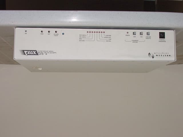
Click to zoom
Application Details
- Equipment Class
- NII - Unlicensed National Information Infrastructure TX
- Date of Grant
- Jun 04, 2001
- Application Purpose
- Original Equipment
- Date of Application
- Jun 04, 2001
- Equipment Note
- UNII Radio
- Frequency Range
- 5275.00000000 - 5325.00000000
- Company
- Proxim Wireless Corporation
- Country
- United States
Documents & Files
Document Text
Text extracted from the exhibit documents filed with the FCC. Open a document above to read the original.
Users Manual
INSTALLATION AND MAINTENANCE MANUAL DS-3 (45 Mbps), wayside T1 LICENSE-FREE RADIOS 5.3/5.8 GHz (U-NII, LE-LAN) INSTALLATION AND MAINTENANCE MANUAL LYNX DS-3 (45Mbps) LICENSE-FREE (U-NII, LE-LAN) RADIOS MARCH 2000 i Installation and Maintenance Manual Copyright (c) 2001 by Western Multiplex Corporation. All rights reserved. No part of this manual may be reproduced without prior written permission from Western Multiplex. The information contained in this manual is subject to change without notice. Western Multiplex shall not be liable for errors contained herein or for incidental or consequential damages in connection with the furnishing, performance, or use of this manual or equipment supplied with this manual. Western Multiplex makes no warranty of any kind with regard to this manual or any equipment supplied with this manual, including, but not limited to, the implied warranties of merchantability and fitness for a particular purpose. Heliax is a registered product of Andrews Corporation. Fireberd is a registered product of Telecommunications Techniques Corporation. Printed in the United States of America Notice: Y2K (Year 2000 Issue) All software supplied by and for Western Multiplex products adheres to the four-(4) digit year nomenclature as required for Year 2000 compliance. Western Multiplex Corporation 1196 Borregas Avenue Sunnyvale, CA 94089-1302 TEL : (408) 542-5200 FAX : (408) 542-5300 P/N:MAN-27701 Issue: January 2001 INSTALLATION AND MAINTENANCE MANUAL LYNX DS-3 (45 Mbps) LICENSE-FREE (U-NII, LE-LAN) RADIOS MARCH 2000 ii This page intentionally left blank INSTALLATION AND MAINTENANCE MANUAL LYNX DS-3 (45Mbps) LICENSE-FREE (U-NII, LE-LAN) RADIOS MARCH 2000 iii Regulatory Notice This equipment has been tested and found to comply with the limits for a class B digital device, pursuant to Part 15 of the FCC Rules. These limits are designed to provide reasonable protection against harmful interference in a residential installation. This equipment generates, uses and can radiate radio frequency energy and, if not installed and used in accordance with the instructions, may cause harmful interference to radio communications. However, there is no guarantee that interference will not occur in a particular installation. If this equipment does cause harmful interference to radio or television reception, which can be determined by turning the equipment off and on, the user is encouraged to try to correct the interference by one or more of the following measures: *Reorient or relocate the receiving antenna. *Increase the separation between the equipment and receiver. *Connect the equipment into an outlet on a circuit different from that to which the receiver is connected. *Consult the dealer or an experienced radio/TV technician for help. Shielded cables and I/O cords must be used for this equipment to comply with the relevant FCC regulations. Changes or modifications not expressly approved in writing by Western Multiplex may void the user's authority to operate this equipment. This device complies with RSS-210 and/or RSS-139 of Industry Canada. Operation is subject to the following two conditions: (1) this device may not cause interference, and (2) this device must accept any interference, including interference that may cause undesired operation of the device. This device is intended to be installed by qualified professional personnel. INSTALLATION AND MAINTENANCE MANUAL LYNX DS-3 (45 Mbps) LICENSE-FREE (U-NII, LE-LAN) RADIOS MARCH 2000 iv This page intentionally left blank INSTALLATION AND MAINTENANCE MANUAL LYNX DS-3 (45Mbps) LICENSE-FREE (U-NII, LE-LAN) RADIOS MARCH 2000 v W/CS97-1 GENERAL TERMS 1.1 All Definitions contained in Western Multiplex's Conditions of Sale (Western Multiplex document number CS96-8), apply to the Warranty. 1.2 Subject to the provisions of the Warranty, Western Multiplex warrants that the equipment described in Paragraph 1.3 shall conform to their specifications described in Paragraph 1.4 in all material respects and that the equipment shall be free from material defects in materials and workmanship. 1.3 This Warranty applies to all original purchases of Western manufactured equipment and accessories (collectively the "Equipment"). 1.4 This Warranty applies to the specifications contained in the most recent version of the manual for the model of the Equipment purchased (the "Specifications"). 1.5 This Warranty does not apply to the following items of Equipment which are covered by the Original Equipment Manufacturer's warranty: (a) antenna systems, including coax cable, waveguide, connectors flex-sections, mounts, other parts of the antenna system and installation materials; (b) non-Western manufactured rack mounted equipment that is assembled wired and tested at Western's factory or supplied as part of a system, including orderwire items, channel banks, multiplexers, fuse/alarm panels, remote alarm items; and (c) equipment which is not listed in Western Multiplex's price book. 1.6 The effective period of this Warranty shall start on the date of shipment of the Equipment and shall end: (a) for all unlicensed radio products and for all licensed digital microwave radio products, two (2) years later; (b) for all analog microwave radio products, three (3) years later; or (c) for all baseband products, five (5) years later (in each case the "Warranty Period"). 1.7 The Customer acknowledges that Western does not represent or warrant that the services provided by Western under this Warranty will ensure uninterrupted or error-free operation of the Equipment. RETURN OF EQUIPMENT UNDER WARRANTY 2.1If an item of Equipment malfunctions or fails in normal intended usage and maintenance within the applicable Warranty Period: (a) the Customer shall promptly notify Western Multiplex of the problem and the serial number of the defective item; (b) Western Multiplex shall, at its sole option, either resolve the problem over the telephone or provide the Customer with a Returned M…
Text truncated - open the document above for the full version.
Users Manual
Antenna TypeManufacturerModel NumberMid-band Gain (dBi) 1 Foot Flat PanelGabrielDFPD1-5223.5 AndrewFPA5250D12-N23.6 2 Foot Flat PanelGabrielDFPD2-5228 AndrewFPA5250D24-N28.2 2 Foot ParabolicGabrielSSP2-52B28.5 GabrielSSD2-52A28.4 GabrielHSSP2-5228.1 Radio WavesSP2-5.228.3 Radio WavesSPD2-5.228.1 AndrewP2F-5229.4 AndrewPX2F-5229.4 3 Foot ParabolicRadio WavesSP3-5.231.4 Radio WavesSPD3-5.231.1 AndrewP3F-5233.4 AndrewPX3F-5233.4 4 Foot ParabolicGabrielSSP4-52A34.2 GabrielSSD4-5234.1 GabrielHSSP4-5233.9 Radio WavesSP4-5.234.6 Radio WavesSPD4-5.234.4 6 Foot ParabolicGabrielSSP6-52A37.5 GabrielSSD6-5237.4 GabrielHSSP6-5237.2 Radio WavesSP6-5.237.7 Radio WavesSPD6-5.237.5 8 Foot ParabolicGabrielSSP8-5239.8 GabrielSSD8-5239.7 GabrielHSSP8-5239.6 Feeder Loss Type ManufacturerModel NumberLoss/100'Notes 1/2" foam coaxAndrewLDF 4-506.6 dBadd ~0.25 dB per connector 5/8" foam coaxAndrewLDF 4.5-504.7 dBadd ~0.25 dB per connector WaveguideAndrewEW-521.2 dBdoes not include transitions Formula for determining maximum output power setting for 5.25-5.35 GHz U-NII (LE-LAN) Transmitters (@ EIRP=30dBm): Max Tx (dBm) is the lesser of 23dBm and 30 - G + FL where: G = Antenna Gain FL = Feeder Loss including connectors Note: All Western Multiplex radios require professional installation. Antennas with gain less than 23.5 dBi are not allowed Antennas of other make may be used with the HZB-U53-45 device, but must be of the same type, dimensions and gain as those listed
Attestation Statements
March 23, 2001 Intertek Testing Services 1365 Adams Ct. Menlo Park, CA 94025 STATEMENT THAT HZB-U53-45 (UNII) RADIOS MUST BE PROFESSIONALLY INSTALLED AND SO IS EXEMPT FROM THE ANTENNA RESTRICTIONS OF FCC PART 15.203, INCLUDING INFORMATION ON ANTENNAS USED FOR TESTING This letter is submitted with regards to professional installation of the HZB-U53-45 (UNII) radio and the antennas used for testing. The HZB-U53-45 (UNII) radios must be professionally installed and so is exempt from the antenna restrictions of FCC Part 15.203. The HZB-U53-45 (UNII) radio is a product manufactured by Western Multiplex in Sunnyvale, California. The HZB-U53-45 (UNII) radio is to be certified for operation under Part 15.407 of the FCC Rules in the 5.25-5.35 band. This equipment is designed for point-to-point communications and will carry data signals using a DS-3 interface. Due to the unique requirements of installation and integration of these systems, typical consumers or businesses will not have the proper training required for successful implementation of these systems. The HZB-U53-45 (UNII) is not designed for use by the general public, and will be sold as follows: • through the Western Multiplex sales force to professional communications users in the following categories: electric power utilities, cellular telephone operating companies, personal communication service operating companies, regional Bell operating companies, oil and gas exploration and transmission companies, railroad companies, federal, state and local government agencies, or • through designated and professionally trained Western Multiplex Value Added Resellers to business users under individual reseller agreements. These companies will either use their professional telecommunications engineering staff to carry out the installation or will subcontract to professional installation firms. On occasion, a professional installation firm will purchase the HZB-U53-45 (UNII) radios directly. The HZB-U53-45 (UNII) radio will be used for fixed, permanent or temporary, outdoor links requiring the use of directional antennas at 5.2-5.8 GHz, which tend to be mounted on towers. These antennas will have narrow beamwidths and require professional installers to align them. In addition, the HZB-U53-45 (UNII) radio must be set up for the specific line interface required during installation. This procedure must be carried out by a qualified professional installer for the equipment to operate properly. 1196 Borregas Ave., Sunnyvale, CA 94089-1302, USA Tel: +1 (408) 542-5200, Fax: +1 (408) 542-5300 The output power of the HZB-U53-45 (UNII) radio will be adjusted to meet any applicable EIRP limits by the professional installer during installation. The method of adjusting the output power is described in the manual written for use by professionally trained installers. To ensure the worst- case situation is covered, the equipment was tested at the maximum output power. The HZB-U53-45 (UNII) radio is a full duplex device with a common transmit and receive port. The addition of an external amplifier to boost the transmit power would disable the receive signal, thus rendering the HZB-U53-45 (UNII) radio inoperable. In addition, high power amplifiers (not generally available at 5.2-5.8 GHz) cannot be used without ensuring that signal saturation does not occur (because this would produce unrecoverable deterioration of the receive signal). Thus, the addition of an amplifier could not be accomplished by a non-professional installer. The HZB-U53-45 (UNII) radio is typically sold without an antenna, and the customer and/or installation engineer chooses from commercially available antennas. From time to time, Western Multiplex may sell a commercially available antenna along with the HZB-U53-45 (UNII) radio upon customer request. Western Multiplex has also included detailed instructions on how to determine the maximum output power based on EIRP limits for all professional installers to follow. Caroline Yu Homologation Product Manager Western Multiplex Corporation
Attestation Statements
May 22, 2001 To Whom It May Concern: Subject: PSD Compliance In the test report, at 5.3GHz the output power tested is 19.5dBm and 19.2dBm. The PSD tested under that output power is 3.5dBm/MHz and 2.6dBm/MHz. Since the EIRP limit for output power is +30dBm, it allows use of less then 11dBi antenna under the maximum equipment output power. Under such conditions, the PSD of the equipment is under (3.5+11) dBm/MHz, which is within the PSD EIRP limit of 17dBm/MHz. When higher gain antennas are used, output power of the equipment will have to be reduced by an equivalent amount the antenna gain exceeds 11dBi to maintain the +30dBm EIRP limit. This will ensure the reduction of the PSD in the same scale, which will maintain the compliance of PSD to the +17dBm/MHz limit. Example showing compliance of PSD when using different gain antennas are shown in the following table: G ant P out limit [30-G ant ] dBm PSD [3.5 – (19.5- P out limit )] dBm/MHz PSD limit 11-(G ant -6) dBm/MHz 23.5dBi 6.5 -9.5 -6.5 28.5dBi 1.5 -14.5 -11.5 34.2 -4.2 -20.2 -17.2 37.5 -7.5 -23.5 -20.5 39.8 -9.8 -25.8 -22.8 There are instructions in the Installation and Maintenance manual to professional installers on how to adjust equipment output power to ensure EIRP limit is maintained. Caroline Yu Homologation Product Manager Western Multiplex Corporation 1196 Borregas Ave., Sunnyvale, CA 94089-1302, USA Tel: +1 (408) 542-5200, Fax: +1 (408) 542-5300
Cover Letter(s)
January 23, 2001 Federal Communications Commission Authorization and Evaluation Division 7435 Oakland Mills Road Columbia, MD 21046 We, the undersigned, hereby authorize Intertek Testing Services to act on our behalf in all matters relating to applications for equipment authorization, including the signing of all documents relating to these matters. Any and all acts carried out by Intertek Testing Services on our behalf shall have the same effect as acts of our own. We also hereby certify that no party to the applications authorized hereunder is subject to a denial of benefits, that includes FCC benefits, pursuant to Section 5301 of the Anti-Drug Abuse Act of 1988, 21 U.S.C. 853 (a). This agreement expires one year from the current date. Caroline Yu Homologation Product Manager Western Multiplex Corporation 1196 Borregas Ave., Sunnyvale, CA 94089-1302, USA Tel: +1 (408) 542-5200, Fax: +1 (408) 542-5300
Cover Letter(s)
Apr. 9, 01 To Whom It May Concern: Subject: Compliance to 15.407(g) Emissions of the HZB-U53-45 equipment will be maintained within the band under all conditions of normal operation under the worst case of frequency shift. For your reference, the following table shows the specifications of the determining oscillators and the total frequency stability of the equipment over the full operating temperature range. The data shown on the table covers the worst frequency shift situation within the full operating temperature range of –30 to +65C specified for the equipment under application. The oscillators are crystal types. 5.3 GHz Transmitter Fundamental Oscillator (PN: 1900012-414000-000) 140MHz ± 10ppm or ±1.4 kHz RF reference Oscillator (PN: 4820720-401200-000) (12 MHz ± 5ppm) x 432.125 or ±25.93kHz Total Frequency Stability ±27.33kHz The supporting reasoning for the claim is as follows: a) The lowest channel center frequency is 5275 MHz, with a 26dBc width of 37.5 MHz. The margin below the 26dBc points to the lower band edge is 6.25 MHz. b) The highest channel center frequency is 5325 MHz with a 26dBc width of 37.3 MHz. The margin above the 26dBc points to the upper band edge is 6.35 MHz. c) Therefore, the frequency stability of the frequency-determining element must be no worse than 0.118% (min (6.25 MHz/5270 MHz, 6.35 MHz/5325 MHz) over the normal operating range to maintain the emissions within the allowed band. From the above table, it can be seen that the frequency-determining components offer much superior stability to ensure the compliance to 15.407(g). Caroline Yu Homologation Product Manager Western Multiplex Corporation 1196 Borregas Ave., Sunnyvale, CA 94089-1302, USA Tel: +1 (408) 542-5200, Fax: +1 (408) 542-5300
Cover Letter(s)
To: Caroline Yu @ Western Multiplex Cc: David Chernomordik ITS/ES-Mpk Subject: FW: FCC ID: HZB-U53-45; addendum Caroline: One more item. I cannot find schematic diagrams for this product among the files submitted so far. These will be held confidential, per the letter request (along with the detailed operational description, block diagram, and internal photos). Can you provide? Thanks, Roland -----Original Message----- From: Roland Gubisch ITS/ES-Box Sent: Thursday, May 10, 2001 6:52 PM To: 'Caroline Yu @ Western Multiplex' Cc: David Chernomordik ITS/ES-Mpk Subject: FCC ID: HZB-U53-45 Caroline: My review of the application so far indicates only the following issues: 1) PSD compliance. A table showing PSD compliance for the various antennas is needed. This was furnished for the prior application, and a copy of that one is attached. Please update for relevance to the present application and send to me. 2) FCC ID label location. The photos of the label are fuzzy and the label text can't be read. Please furnish an electronic copy of the artwork drawing, showing the text clearly. Also, the label location is not obvious from the photos. Can you provide a photo further away from the EUT, and perhaps annotate with an arrow pointing to the label? 3) Configuration photos. David C: Can you provide a line-conducted config. photo, and clearer versions of the photos shown on page 42 of the PDF file, taken with the patch antenna? (One of these may be the line conducted setup, but it is not clear enough to tell.) Thank you, Roland
Cover Letter(s)
January 29, 2001 Intertek Testing Services 1365 Adams Court Menlo Park, CA 94025 Re: Western Multiplex, Tsunami (UNII) Radio Request for withholding from public disclosure proprietary information submitted pursuant to an application for certification of a UNII band radio. FCC ID: HZB-U53-45 Dear Sir or Madam: Western Multiplex requests that certain materials submitted with this application for certification of the Tsunami (UNII) radio be withheld from public disclosure. This request is made under the provision of Section 0.457 (d) of the Commission’s Rule and Section 552 (b) (4) of the Freedom of Information Act, Trade Secrets. The items marked “Confidential” contain detailed block diagrams, schematic diagrams, and a detailed theory of operation submitted to the FCC for review with this application. The information contains proprietary information (trade secrets) regarding the circuit operation and capabilities (specific values of components, circuit design details and system architecture) which are the result of our extensive investment in research and development. Without the disclosed information, competitive organizations would take considerable more time to assess and develop a workable competitive product. As a result, we believe that disclosure of these company guarded materials would compromise our leading position in this market. We therefore formally request that the materials marked “Confidential” be kept strictly confidential and not made available for inspection by any other party, except on a need to know basis for the sole purpose of the certification process. Caroline Yu Homologation Product Manager Western Multiplex Corporation 1196 Borregas Ave., Sunnyvale, CA 94089-1302, USA Tel: +1 (408) 542-5200, Fax: +1 (408) 542-5300
External Photos
FCC ID: HZB-U53-45 FCC ID: HZB-U53-45 FCC ID: HZB-U53-45 FCC ID: HZB-U53-45
ID Label/Location Info
FCC ID: HZB-U53-45 FCC ID: HZB-U53-45
Internal Photos
FCC ID: HZB-U53-45 FCC ID: HZB-U53-45 FCC ID: HZB-U53-45 FCC ID: HZB-U53-45 FCC ID: HZB-U53-45 FCC ID: HZB-U53-45 FCC ID: HZB-U53-45 FCC ID: HZB-U53-45 FCC ID: HZB-U53-45 FCC ID: HZB-U53-45 FCC ID: HZB-U53-45 FCC ID: HZB-U53-45 FCC ID: HZB-U53-45 FCC ID: HZB-U53-45 FCC ID: HZB-U53-45 FCC ID: HZB-U53-45 FCC ID: HZB-U53-45 FCC ID: HZB-U53-45
Parts List/Tune Up Info
P.O. Box 70, Scarborough, Maine 04070 U.S.A. Tel: 207-883-5161Fax: 207-883-4469 email: [email protected]: http://www.gabrielnet.com 137 2 / 6 GHz Dual Band Electrical Specifications Associated Equipment InformationPages Point-to-Point Antenna Specifications................................. 14 - 111 Special Application Antennas.............................................135 - 145 Antenna Mounts & Reference Dimensions.......................112 - 134 Radomes................................................................................122 - 124 Tower Accessories.............................................................146 - 154 Transmission Lines..............................................................155 - 243 Dry Air Pressurizers............................................................244 - 253 5 GHz Directional Flat Panel Antenna Directional Flat Panels 5.250 - 5.850 GHz Directional Flat Panel Antenna 5 GHz - Spread Spectrum / NII Band Directional Flat Panel Antenna (for Point-to-Point applications) Facts & Features • Gabriel Quality and Dependability. • Lightweight and durable construction. • Quick and easy installation. • Feed input, Type N Female connector. (Other types available on request.) • Input connector positioned on back of antenna assembly. • Antenna supplied with paintable rigid radome. • All Gabriel antennas meet or exceed Standards EIA-195-C and EIA-222-F. • Antenna accommodates +/-20° elevation adjustment. (Specific installation limitations may apply.) • Mini-Mounts accommodate a 1.9 in. to 4.5 in. (48 to 114 mm) O.D. mast pipe. Quick-Align Mounts mount to a 2.375 in. (60 mm) O.D. mast pipe. An optional 1.9 in. (48 mm) to 4.5 in. (114 mm) Mast Clamp Kit is available on request for the Quick-Align Mount. • To adapt the Quick Align Mount for use on a 1.9 in. to 4.5 in. O.D. mast pipe order Mast Clamp Kit MCKQ-19-45 • Special colors and / or logos available on request. • Dual band models are available on request. Diagonal - Directional Flat Panel - Plane Polarized DFPS.5-52**0.5(0.15)MM17.518.0 18.419.030351.50(14.0) DFPD1-521(0.3)MM23.023.5 23.99.430431.50(14.0) DFPD1-52 (M1)1(0.3)QAM23.023.5 23.99.430431.50(14.0) DFPD2-522(0.6)QAM27.528.0 28.44.630461.50(14.0) NOTE: Product information subject to change without notice. Other polarization configurations available. 5.250 - 5.850 MM=Mini - Mount QAM=Quick Align Mount VSWR (R.L. max. dB) Frequency GHz Model Number Diameter ft (m) Mount Type Gain at Low Mid High dBi Nominal Mid-Band Beamwidth degrees XPD dB F/B ratio dB ** Note: The DFPS.5-52 antenna model is square in configuration.
Parts List/Tune Up Info
P.O. Box 70, Scarborough, Maine 04070 U.S.A. Tel: 207-883-5161Fax: 207-883-4469 email: [email protected]: http://www.gabrielnet.com 59 5.250 - 5.850 GHz Parabolic Antennas 5.250 - 5.850 GHz Facts & Features • Gabriel Quality and Dependability. • Innovative Feed Design. • Feed input is Type N Female, 50 ohm. • Isolation is 35 dB on Dual Polarized models. • Optional radomes available. • 2 ft. (0.6) model feeds are installed from the front of the antenna. 4 ft. (1.2), 6 ft. (1.8) and 8 ft. (2.4) model feeds are installed from the rear of the antenna, and allow for inspection or replacement from the rear. These models allow for smooth polarization adjustment from the back of the antenna. • Gabriel’s Quick Align Mount comes standard on the SSP2, SSD2 and HSSP2 models. This mount allows for quick installation and easy alignment of the antenna with two hand tools. The Quick Align Mount will mount to a 1.9 - 4.5 in OD mast pipe. • New environmentally pleasing neutral colors. • Dual band models are available. Electrical Specifications 5.250 - 5.850 Standard & High Performance Plane - Dual Polarized Unlicensed "NII" and Spread Spectrum / "ISM" Bands (National Information Infrastructure) (Industrial, Scientific & Medical) NOTE: †Improved VSWR available. Product information subject to change without notice. Gabriel "UNII" and "ISM" Band 2-ft. (0.6 m) - Plane Polarized - Standard Parabolic Antenna 5.250 - 5.850 Associated Equipment InformationPages Point-to-Point Antenna Specifications................................. 14 - 111 Special Application Antennas............................................135 - 145 Antenna Mounts & Reference Dimensions.......................112 - 134 Radomes..............................................................................122 - 124 Tower Accessories............................................................146 - 154 Transmission Lines.............................................................155 - 243 Dry Air Pressurizers...........................................................244 - 253 Size ft (m) VSWR (R.L. max. dB) Gain at Low Mid High dBi F/B ratio dB Standard Frequency GHz Model Number Nominal Mid-Band Beamwidth degrees XPD dB See the Special Application section of this catalog for Gabriel’s Directional Flat Panel antennas for Spread Spectrum operation. Standard - Plane Polarized SSP2-52B2(0.6)-28.128.5 29.06.125381.50(14.0)† SSP4-52A4(1.2)-33.634.2 34.63.130461.50(14.0)† SSP6-52A6(1.8)-37.037.5 38.02.130491.50(14.0)† SSP8-528(2.4)-39.439.8 40.31.630521.50(14.0)† Standard - Dual Polarized SSD2-52A2(0.6)-28.028.4 28.96.130381.50(14.0)† SSD4-524(1.2)-33.534.1 34.53.130461.50(14.0)† SSD6-526(1.8)-36.937.4 37.92.130491.50(14.0)† SSD8-528(2.4)-39.339.7 40.21.630521.50(14.0)† High Performance - Plane Polarized HSSP2-522(0.6)-27.728.1 28.66.130431.50(14.0)† HSSP4-524(1.2)-33.333.9 34.33.130501.50(14.0)† HSSP6-526(1.8)-36.737.2 37.72.130581.50(14.0)† HSSP8-528(2.4)-39.239.6 40.11.630621.50(14.0)† 050900 5.250 - 5.850
RF Exposure Info
Attention: Reviewing Engineer The HZB-U53-45 radio is a full duty-cycle product exclusively designed for fixed-mount point-to-point applications. Each radio’s inputs are connected to external equipment through the radio’s interfaces. The RF output port is connected to a RF cable or a waveguide, which connects on the other side to an antenna usually installed on top of a building or a tower. It is impossible to use the radio in any mobile applications. The HZB-U53-45 radio antennas need to be professionally installed outdoor either on top of a tower or a tall building. The installation sites are inaccessible to the general public. Only installation engineers may get close to the radio antenna during system installation. For the safety concern of the professional installers, we put a warning message on Page 3-22 of the product manual recommending installers stay at least 5 meters away from the antenna during system operation. The maximum output power tested for the HZG-U53-45 is below 1 W (30 dBm), and the biggest antenna could possibly be used with the radio is of 2’ in diameter (28.4 dB gain). To comply with the U-NII EIRP limits, when a higher gain antenna is used, the output power will be reduced to make the overall EIRP less then +30dBm at the 5.25-5.35dBm band. At +30dBm EIRP, the power density at 1.5 meters from an antenna is: S = EIRP/4πR 2 =0.035 W/m 2 << 1 mW/cm 2 Where: S = Power density R = distance to the center of radiation of the antenna The near field power density is : S nf = 16ηP/π D 2 . The worst case of near-field power density is when the radio output at the certified power, η=1 S nf max = 16x0.089/π (2x0.3048) 2 = 1.2 W/m 2 = 0.012 mW/cm 2 <1 mW/cm 2 Where: S nf = maximum near –field power density P = power fed to the antenna η = aperture efficiency D = antenna diameter Therefore, the power density is compliant with the limit for General Population/ Uncontrolled Exposure as specified in rule 1.1310. If you should have any questions regarding this submission, please feel free to contact the undersigned. Yours truly, Caroline Yu Homologation Product Manager Western Multiplex Corporation 1196 Borregas Ave., Sunnyvale, CA 94089-1302, USA Tel: +1 (408) 542-5200, Fax: +1 (408) 542-5300
Test Report
Intertek Testing Services I Radiated Emissions Tes 1.06E+4 37.2Peak 14 10 39.839.57.00.074.0-29.5 v 44.5 1.06E+427.0Ave14 10 v 39.839.57.00.034.354.0-19.7 1.58E+4 36.5Peak 14 10H42.2 38.48.70.049.074.0-25.0 1.58E+427.0Ave14 10 H42.2 38.48.70.039.554.0-14.5 2.11E+4 37.0 Peak21 13 v 40.323.310.2-9.554.774.0-19.3 2.11E+4 27.2Ave2113 v 40.323.310.2 -9.5 44.954.0 -9.1 3.17E+445.0Peak22 1343.525.90.0 -9.553.174.0-20.9H 3.17E+435.0Ave 22 13 H 43.525.90.0-9.543.154.0-10.9 Intertek Testing Services I Radiated Emissions Tet I Model #: 27750 Company: Western Multiplex Corporatrion EUT:U-NII Radio IFCCID HZB-U53-45 11 Project #: J20033825ITest Date: December 10, 20003 Test Mode: Engineer: Xi-Ming y 0 Tx @ 5325 MHz, DFPD 1-52 Antenna 1.07E+437.5Peak14 10 v 39.839.57.0 0.0 44.874.0-29.2 1.07E+427.3Ave14 10 v 39.839.5 7.00.0 34.6 54.0-19.4 1.60E+436.0Peak14 10 v 42.338.48.7 0.0 48.6 74.0-25.4 1.60E+426.0Ave 14 10 v 42.338.4 8.70.038.654.0-15.4 2.13E+437.0Peak21 13 v 40.323.310.2-9.554.774.0 -19.3 2.13E+427.2 Ave2113 v 40.323.310.2-9.544.954.0-9.1 Intertek Testing Services I Radiated Emissions Tes 39.5 0.044.374.0-29.7I.O6E+4 37.0 Peak1410v 39.87.0 27.8 v 39.839.5 7.0 0.0 35.154.018.9 I.O6E+4Ave. 1410 1.58E+436.8Peak 14 10 H42.2 38.48.70.0 49.374.0-24.7 1.58E+427.9Ave.1410 H 42.238.48.70.040.454.013.6 1340.323.310.2-9.5 54.974.019.1 2.IIE+437.2Peak 21v 2.11E+427.4211340.323.310.2-9.545.1 54.0-8.9 Ave. v 3.17E+445.3 Peak2213H43.525.90.0-9.553.474.0-20.6 3. 17E+4 35.2 2213 43.525.90.0 -9.543.354.010.7Ave.H Intertek Testing Services I Radiated Emissions Te I.O7E+438.0Peak14 10 v 39.839.5 7.00.045.374.0-28.7 I.O7E+427.910 v 39.839.57.00.035.254.0 Ave14 -18.8 1.60E+436.5Peak14 10 v 41.838.48.8 0.0 I48.774.0.25.3 0.0 I 1.60E+4 26.5Ave 14 10 v 41.8 38.48.838.754.0-15.3 2.13E+437.1 Peak 211340.323.3 -9.554.8 v 10.274.0-19.2 2.13E+427.22113 v 40.3 23.310.2-9.5 44.9 54.0-9.1 Ave
Test Report
A Radiated Emissions Test Data Company:Western Multiplex CorporatrionModel #:27750StandardFCC § 15.247 (R.B.) EUT:Tsunami U-NII RadioFCC ID: HZB-U53-45Limits11 Project #: J20033825Test Date:March 22. 1001Test Distance_3meters Test Mode:Tx @ 5325MHz With Gabriel AntennaEngineer:Xi-Ming Y.Duty Relaxation0dB Antenna UsedPre-Amp UsedCable UsedTransducer Used Number:1421221013012000 Model:EMCO 3115 3160-9 3160-10AFT18855ACO/400NoneNPS366NoneNoneNone FrequencyReadingDetectorAnt.Amp.Ant. Pol.Ant. FactorPre-AmpInsert. LossD. C. F.NetLimit @3mMargin MHzdB(μV)P/A/Q##H/VdB(1/m)dBdBdBdB(μV/m)dB(μV/m)dB 1.07E+438.0Peak1410V39.839.57.00.045.374.0-28.7 1.07E+427.9Ave.1410V39.839.57.00.035.254.0-18.8 1.60E+436.5Peak1410V41.838.48.80.048.774.0-25.3 1.60E+426.5Ave.1410V41.838.48.80.038.754.0-15.3 2.13E+437.1Peak2113V40.323.310.2-9.554.874.0-19.2 2.13E+427.2Ave.2113V40.323.310.2-9.544.954.0-9.1 Note…
Text truncated - open the document above for the full version.
Contact Information
Applicant
Ken Lim(Accounting Manager)
Technical Contact
Intertek Testing ServicesDavid Chernomordik
[email protected]650-463-2900
1365 Adams Court · Menlo Park, California · United States
Non-Technical Contact
Western Multiplex Corp.Caroline Yu
[email protected]408-542-5323
Test Firm
Intertek Testing Services NA Inc.John Quigley
Technical Specifications
| # | Rule Parts | Frequency Range | Power Output |
|---|---|---|---|
| 1 | 15E | 5.28 GHz - 5.33 GHz | 9.00 mW |
Other Applications from Proxim Wireless Corporation
HZB-MEGA6
Aug 12, 2026EdgeAX 6GHz Radio Module
Equipment Class
6FC - 15E 6 GHz Fixed Client
HZB-GIGA5
Sep 21, 2023Startum X5 Gigabit 5 GHz Radio
Equipment Class
NII - Unlicensed National Information Infrastructure TX
HZB-NGPAP
Apr 26, 2021NGP LC 2.4 & 5 GHz Radios
Equipment Class
NII - Unlicensed National Information Infrastructure TX
HZB-NGPLC
Mar 04, 2021NGP LC 5 GHz Radio
Equipment Class
DTS - Digital Transmission System
HZB-NGP1058W
Nov 03, 2015802.11 ac PCIe Module
Equipment Class
DTS - Digital Transmission System