HZB-U58-S60Unlicensed NII Transceiver
Proxim Wireless Corporation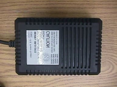
Click to zoom
Application Details
- Equipment Class
- NII - Unlicensed National Information Infrastructure TX
- Date of Grant
- Nov 01, 2001
- Application Purpose
- Original Equipment
- Date of Application
- Nov 01, 2001
- Equipment Note
- Unlicensed NII Transceiver
- Frequency Range
- 5740.00000000 - 5810.00000000
- Company
- Proxim Wireless Corporation
- Country
- United States
Documents & Files
Document Text
Text extracted from the exhibit documents filed with the FCC. Open a document above to read the original.
Users Manual
WESTERN MULTIPLEX CORPORATION Installation and Maintenance Manual Multipoint MAN 40000-001d1 TSUNAMI MULTIPOINT iiii Revisions: September 2001 Draft October FCC submittal WESTERN MULTIPLEX CORPORATION Tsunami Point-to-Multipoint 2001 Western Multiplex Corporation 1196 Borregas Avenue Sunnyvale, California 94089 USA Phone +1 408 542 5200 • Fax +1 408 542 5300 http://www.wmux.com ftp://ftp.wmux.com/products/ ii Table of Contents 1. INTRODUCTION............................................................................................................................1-1 PRODUCT HIGHLIGHTS.........................................................................................................................1-2 KEY FEATURES....................................................................................................................................1-3 HOW TO USE THIS MANUAL.......................................................................................................................1-3 SAFETY INSTRUCTIONS...............................................................................................................................1-4 2. SYSTEM OVERVIEW.....................................................................................................................2-1 SITE PLANNING CONSIDERATIONS...............................................................................................................2-2 General Considerations..........................................................................................................................2-2 Weather................................................................................................................................................2-3 Antennas...............................................................................................................................................2-5 Path Planning........................................................................................................................................2-6 WIRELESS: FREQUENTLY ASKED QUESTIONS................................................ERROR! BOOKMARK NOT DEFINED. 3. QUICK SET-UP PROCEDURE........................................................................................................3-1 Important Configuration Notes................................................................................................................3-1 Unpacking the System.............................................................................................................................3-1 SOFTWARE INSTALLATION..........................................................................................................................3-4 HUB SITE EQUIPMENT CONFIGURATION (BSU).............................................................................................3-5 SUBSCRIBER UNIT CONFIGURATION.............................................................................................................3-8 Mechanical Considerations – Mounting Units...........................................................................................3-9 4. SPECIFICATIONS........................................................................................................................4-11 SYSTEM..............................................................................................................................................4-11 STANDARDS COMPL LANCE AND INTERFACES................................................................................4-12 CONFIGURATION AND MANAGEMENT.............................................................................................4-12 POWER /ENVIRONMENT /SAFETY......................................................................................................4-12 PHYSICAL DIMENSIONS....................................................................................................................4-13 MOUNTING (INSTALLATION).............................................................................................................4-13 TSUNAMI MULTIPOINT ii Figures FIGURE 1-1-1: PROPER EARTHING/GROUNDING................................................................................................1-5 FIGURE 2-2-1: EACH HUB IS MADE UP OF ONE TO SIX BASE STATIONS AND MULTIPLE REMOTES(SUS)...................2-1 FIGURE 3-3-1: SUBSCRIBER UNIT....................................................................................................................3-3 FIGURE 3-2 SUBSCRIBER ODU...................................................................................................................3-9 FIGURE 3-3: BASE STATION ODU.................................................................................................................3-10 TSUNAMI MULTIPOINT 1-1 1. Introduction sunami Multipoint is a point-to-multipoint outdoor wireless system offering a high-capacity alternative to wired data networks. Using IP packet radio transmitters, standard Ethernet interfaces, and an easy to-deploy design, the Tsunami Multipoint system enables high-speed network connections to multiple Ethernet switches, routers or PCs from a single location. With Tsunami Multipoint, you can now avoid the delays and costs associated with wired connections such as DSL, cable modems, and leased T I /E I lines. Tsunami Multipoint eliminates wire/fiber installation costs and recurring monthly fees - delivering carrier-class performance at an affordable price. Tsunami Multipoint systems consist of one or more Subscriber Units that communicate with a Base Station to provide high-performance wireless network connections. EXTEND OR ENHANCE YOUR NETWORK OVERNIGHT With Tsunami Multipoint, there are no DSL, cable, or leased-line hassles to negotiate. You no longer have to worry about man-made barriers to overcome. Easy installation and operation allow network planners to quickly deploy up to 60 Mbps capacity between locations, …
Text truncated - open the document above for the full version.
Attestation Statements
Western Multiplex Confidential 15.407(c) Compliance Sept. 17, 2001 page 1 Compliance to 15.407(c) HZB-U58-S60 The HZB-U58-S60 unit is a subscriber unit that operates in a point-to-multipoint network. It only transmits under the following conditions: a) The subscriber unit has received information at its Ethernet interface that is addressed to a destination accessible through the base station. The subscriber unit then transmits a reservation request to base station. The base station will respond with a time slot assignment, of finite duration, for the subscriber unit to transmit the data. b) The base station will periodically “poll” the subscriber units by requesting the subscriber unit to transmit a time slot of pseudorandom data. This is performed to maintain inbound synchronization and power control for each subscriber unit. c) The Control Processor in the subscriber unit only enables dc power to the transmitter circuitry if the following operational conditions are met: (i) The frequency synthesizers are locked. (ii) The subscriber unit receiver is operational and has correctly demodulated a valid control message from the base station during the previous 7.5-ms frame interval. (iii) The transmitter output power is below its allowable limit, as determined by coupling and detecting the output signal and comparing the detector output with a calibrated threshold voltage. (iv) The Control Processor is responding to interrupts as expected (checked by a watchdog timeout). (v) The modem, data buffer, and Ethernet interface is processing data without checksum or synchronization errors. Therefore, it is shown that the subscriber unit will automatically discontinue transmission in the absence of information to transmit or operational failure to ensure compliance with 15.407(c).
Attestation Statements
Western Multiplex Confidential 15.407(g) Compliance Sept. 17, 2001 page 1 Compliance to 15.407(g) HZB-U58-S60 Emissions of the HZB-U58-S60 will be maintained within the band under all conditions of normal operation under the worst case of frequency shift. As described in the theory of operations document, the frequency of the RF signal is completely determined by a single reference oscillator of 20.75MHz frequency. Two vendors have been approved to supply the reference oscillator, part #690-00173-06, and the frequency-stability characteristics of each vendor’s part are shown in the following table. Data sheets are attached for reference. Frequency-Stability Characteristics of Reference Oscillator (p/n 690-00173-06) Characteristic Vectron [email protected] Rakon VTXO220U-20.75MHz Type TCXO TCXO Initial Calibration ±2 ppm ±5 ppm Stability vs.Temperature (-33°C to +70°C) ±2 ±2 Stability vs. Supply Voltage ±0.3 ±0.3 Aging (7years) ±5 ±5 Total: ±9.3 ppm ±12.3 ppm The worst-case stability is ±12.3 ppm, or ±72 kHz, over all operating conditions. This is sufficient to maintain the emissions within the allowable band; the supporting reasoning for this claim is as follows: a) The lowest channel center frequency is 5740.40MHz, with a maximum 26dBc bandwidth of 26MHz. The margin from the lower band edge of 5.725GHz to the lower 26dBc point is 2.4MHz. This margin is greater than the maximum oscillator error of 130kHz. b) The highest channel center frequency is 5809.57MHz, with a maximum 26dBc bandwidth of 26MHz. The margin from the upper band edge of 5.825GHz to the upper 26dBc point is 2.43MHz. This margin is also greater than the maximum oscillator error of 130kHz. Therefore, it is determined that the frequency-determining components offer superior stability to ensure compliance with 15.407(g). MODEL VTXO200U SMD Voltage Controlled Temperature Compensated Crystal Oscillators Small SMD TCXO with standard 4-terminal interface available in custom frequencies ranging from 8.2MHz to 32MHz with a clipped sinewave output. Product Description This Colpitts oscillator uses the direct two-port temperature compensation method. Operating on the fundamental mode, the circular AT-cut crystal is housed in the environmentally rugged UM-1 SLIM resistance weld package. The product can be configured to operate on any voltage between 2.7V and 5V. A mechanical trimmer is available for adjusting the frequency. Customized frequencies readily available make this model suitable for many timing and frequency applications. Applications include GPS, TDMA/APMS/CDMA cellular and satellite phones, PCMCIA CDPD cards, two-way pagers and many other wireless possibilities. Features Uses the high performance UM-1 slim crystal Excellent phase noise performance, very little aging and low temperature hysteresis under high vibration environments Clipped sinewave frequency output (8.2MHz to 32MHz) Standard temperature stability choices are +/-1ppm, +/-1.5ppm and +/-2.5ppm, over wide temperature range This product has no trimmer to allow for an aqueous wash process Non-standard frequencies available on quick turn around Frequency control ranges from 6 to 50ppm available 1.0 SPECIFICATION REFERENCES 1.1 Model Description VTXO220U 20.75 MHz 1.2 Reference Number 1133 1.3 Company WirelessHome 1.4 Rakon Internal Part No. TX2046 2.0 FREQUENCY CHARACTERISTICS Line Parameter Test Condition Min.Max. Units 2.1 Nominal Frequency Nominal Frequency referenced to 25 deg. C. 20.75MHz 2.2 Frequency calibration Frequency at 23 deg. C +/-2 deg. C (see Note 1) 3.0 +/-ppm 2.3 Frequency stability over temperature Referenced to frequency reading at 25 deg. C. Temperature varied at max. of 2 deg. C per minute. Control voltage varied between min. and max. (Note 2) 2.0 +/-ppm 2.4 Temperature range The operating temperature range over which the frequency stability is measured (Note 3) -30.075.0 Degrees C 2.5 Frequency perturbations Peak to peak amplitude of frequency perturbation within operating temperature range (Note 1) 0.5 ppm 2.6 Frequency slope of perturbations Minimum of 1 frequency reading every 2 degrees C, over the operating temperature range (Note 1) 0.5 ppm/deg C © 1998 Rakon Limited PG 01 PRODUCT SPECIFICATION 2.7Static temperature hysteresis Frequency change after reciprocal temperature ramped over the operating range. Frequency measured before and after at 25 deg C. 0.4+/-ppm 2.8Supply voltage stability Supply voltage varied +/-5% at 25 deg C. Frequencies above 25MHz are not able to be specified below the max. value given. (Note 1) 0.3+/-ppm 2.9Load sensitivity +/-10% load change 0.2+/-ppm 2.10 Root Allan Variance 1 second Tau. (Note 1) 1.0ppb 2.11 Long term stability Frequency drift over 1 year (Note 1) 1.0+/-ppm 2.12 Long term stability (10 years) Frequency drift over 10 years (note 1) 0.05.0+/-ppm 2.13 G Sensitivity Gamma vector of all three axes from 30Hz to 1500Hz (Note 1) 1.0ppb/G 3.0 POWER SUPPLY LineParameterTest ConditionMin. Max.Units 3.1Supply voltage Supply voltage range based on nominal 3.3V 3.14 3.46V 3.2Current At Max. supply voltage 2.0mA 4.0 CONTROL VOLTAGE LineParameterTest ConditionMin. Max.Units 4.1 Control voltage range Determined by supply voltage. Nominal control 1.65V 0.52.8V 4.2Frequency tuning Frequency shift from Min. to Max. control voltages (Note 6) 24.0ppm 4.3Frequency tuning linearity Deviation from straight line curve fit (Note 1) 20.0% 4.4Port input impedance 100.0K Ohms 5.0 OSCILLATOR OUTPUT LineParameterTest ConditionMin. Max.Units 5.1Output waveform Clipped sinewave. 5.2Output voltage level At min. supply voltage 0.8V 5.3Output load resistance Operating range 18.0 22.0K Ohms 5.4Output load capacitance Operating range 4.55.5pF 6.0 SSB PHASE NOISE LineParameterTest ConditionMin. Max.Units Quiescent measurement at room temperature. Phase noise dependent on oscillator frequency. 6.1SSB Phase noise density 1Hz offset -45.0 dBc/Hz 6.2SSB Phase noise density 100Hz offset -105.0 dBc/Hz 6.3SSB Phase noise density 1KHz offset -1…
Text truncated - open the document above for the full version.
Cover Letter(s)
October 4, 2001 Federal Communications Commission Authorization and Evaluation Division 7435 Oakland Mills Road Columbia, MD 21046 We, the undersigned, hereby authorize Intertek Testing Services to act on our behalf in all matters relating to applications for equipment authorization, including the signing of all documents relating to these matters. Any and all acts carried out by Intertek Testing Services on our behalf shall have the same effect as acts of our own. We also hereby certify that no party to the applications authorized hereunder is subject to a denial of benefits, that includes FCC benefits, pursuant to Section 5301 of the Anti-Drug Abuse Act of 1988, 21 U.S.C. 853 (a). This agreement expires one year from the current date. Caroline Yu Homologation Product Manager Western Multiplex Corporation 1196 Borregas Ave., Sunnyvale, CA 94089-1302, USA Tel: +1 (408) 542-5200, Fax: +1 (408) 542-5300
Cover Letter(s)
October 4, 2001 Federal Communications Commission Authorization and Evaluation Division Laboratory Division 7435 Oakland Mills Road Columbia, MD 21046 Re: Western Multiplex, Tsunami (UNII) Radio Request for withholding from public disclosure proprietary information submitted pursuant to an application for certification of a UNII band radio. FCC ID: HZB-U58-S60 Dear Sir or Madam: Western Multiplex Corporation requests that certain materials submitted with this application for certification of the Tsunami (UNII) radio be withheld from public disclosure. This request is made under the provision of Section 0.457 (d) of the Commission’s Rule and Section 552 (b) (4) of the Freedom of Information Act, Trade Secrets. The items marked “Confidential” contain detailed block diagrams, schematic diagrams, antenna design specifications, a parts list and a detailed theory of operation submitted to the FCC for review with this application. The information contains proprietary information (trade secrets) regarding the circuit operation and capabilities (specific values of components, circuit design details and system architecture), which are the result of our extensive investment in research and development. Without the disclosed information, competitive organizations would take considerable more time to assess and develop a workable competitive product. As a result, we believe that disclosure of these company guarded materials would compromise our leading position in this market. We therefore formally request that the materials marked “Confidential” be kept strictly confidential and not made available for inspection by any other party, except on a need to know basis for the sole purpose of the certification process. Caroline Yu Homologation Product Manager Western Multiplex Corp. 1196 Borregas Ave., Sunnyvale, CA 94089-1302, USA Tel: +1 (408) 542-5200, Fax: +1 (408) 542-5300
RF Exposure Info
Attention: Reviewing Engineer The HZB-U58-S60 radio is designed for fixed-mount point-to-point applications. The device is integrated to an array antenna with maximum gain of 21dBi. The maximum EIRP for the HZB-U58-S60 as defined in FCC 15.407 is +53 dBm. For the worst case EIRP of +53dBm, the power density at 1.5 meters from an antenna is: S = EIRP/4πR 2 =7.1 W/m 2 =0.71 mW/cm 2 < 1 mW/cm 2 Where: S = Power density R = distance to the center of radiation of the antenna Therefore, the power density is compliant with the limit for General Population/ Uncontrolled Exposure as specified in rule 1.1310. If you should have any questions regarding this submission, please feel free to contact the undersigned. Yours truly, Caroline Yu Homologation Product Manager Western Multiplex Corporation 1196 Borregas Ave., Sunnyvale, CA 94089-1302, USA Tel: +1 (408) 542-5200, Fax: +1 (408) 542-5300
Test Report
Appendix A Plots 15.407((b), Out-of-Band emissions 4.a.1 – 4.a.8Ch 0QAM16 4.b.1 – 4.b.8Ch 2QAM16 4.c.1 – 4.c.9Ch 5QAM16
Test Report
1365 Adams Court, Menlo Park, CA 94025 Western Multiplex Corporation, Model No: 40100-XXX FCC ID: HZB-U58-S60Date of Test: September 20 to 23, 2001 Report # 30089281FCC Part 15.407 Certification 1 TABLE OF CONTENTS 1.0SUMMARY OF TESTS......................................................................................................................2 2.0GENERAL DESCRIPTION...............................................................................................................3 2.1PRODUCT DESCRIPTION...........................................................................................................3 2.2RELATED SUBMITTAL(S) GRANTS...........................................................................................4 2.3TEST METHODOLOGY...............................................................................................................4 2.4TEST FACILITY..........................................................................................................................4 3.0SYSTEM TEST CONFIGURATION................................................................................................5 3.1SUPPORT EQUIPMENT AND DESCRIPTION................................................................................5 3.2BLOCK DIAGRAM OF TEST SETUP............................................................................................5 3.3JUSTIFICATION...........................................................................................................................6 3.4SOFTWARE EXERCISE PROGRAM..............................................................................................6 3.5MODE OF OPERATION DURING TEST.........................................................................................6 3.6MODIFICATIONS REQUIRED FOR COMPLIANCE........................................................................6 3.7ADDITIONS, DEVIATIONS AND EXCLUSIONS FROM STANDARDS.............................................6 4.0MEASUREMENT RESULTS............................................................................................................7 4.1CONDUCTED OUTPUT POWER AT ANTENNA TERMINAL........................................................7 4.226 DB BANDWIDTH..................................................................................................................8 4.3POWER DENSITY.....................................................................................................................13 4.4THE RATIO OF THE PEAK EXCURSION OF THE MODULATION ENVELOPE...............................27 TO THE PEAK POWER............................................................................................................................27 4.5OUT-OF-BAND CONDUCTED EMISSIONS................................................................................36 4.6RADIATED EMISSIONS.............................................................................................................38 4.7AC LINE CONDUCTED EMISSION...........................................................................................44 5.0LIST OF TEST EQUIPMENT.........................................................................................................46 6.0DOCUMENT HISTORY..................................................................................................................47 1365 Adams Court, Menlo Park, CA 94025 Western Multiplex Corporation, Model No: 40100-XXX FCC ID: HZB-U58-S60Date of Test: September 20 to 23, 2001 Report # 30089281FCC Part 15.407 Certification 2 1.0Summary of Tests Western Multiplex Corporation, Tsunami Subscriber Unit, Model: 40100-XXX FCC ID: HZB-U58-S60 TestReferenceResults Output power15.407(a)Complies, see sec. 4.1 of this report 26 dB Bandwidth15.407(a)For calculation only, see sec. 4.2 of this report Power Density15.407(a)(5)Complies, see sec. 4.3 of this report The ratio of the peak excursion of the modulation envelope to the peak transmit power 15.407(a)(6)Complies, see sec. 4.4 of this report Out-of-band Antenna Conducted Emission15.407(b)Complies, see sec. 4.5 of this report Spurious Radiated Emission from transmitter15.407(b)Complies, see sec. 4.6 of this report Radiated Emission in Restricted Bands15.109, 15.205Complies, see sec. 4.6 of this report Radiated Emission from digital part and receiver15.109Complies, see sec. 4.6 of this report AC Conducted Emission15.207Complies, see sec. 4.1 of this report Requirement15.407(c)Complies, see file "SU15.407(c)" Requirement15.407(d)Complies, see file "SU15.407(d)" Radiation Exposure Requirement1.1310Complies, see file "RF Exposure Statement" Antenna Requirement15.203Complies, the EUT uses a permanently connected antenna 1365 Adams Court, Menlo Park, CA 94025 Western Multiplex Corporation, Model No: 40100-XXX FCC ID: HZB-U58-S60Date of Test: September 20 to 23, 2001 Report # 30089281FCC Part 15.407 Certification 3 2.0General Description 2.1 Product Description The Tsunami Subscriber Unit consists of two major components: an outdoor unit (ODU) and an indoor power adapter (IPA). The two components are connected with a single category-5 cable (4 unshielded twisted pairs) to transfer direct-current power to the ODU and to transport 10/100BaseT Ethernet data to and from the ODU. The IPA provides a RJ-45 jack to connect the Ethernet data to either a computer or hub/switch. The ODU is an integrated antenna, radio, modem, and Ethernet interface to provide fixed, broadband digital data services for individuals, businesses, and institutions. As the device is used at a remote location to communicate with the Base Station unit at a central location, the transmission of the Subscriber unit is of fixed point-to-point. A pre-production version of the EUT was received on September 18, 2001 in good operating condition. Overview of the Tsunami Subscriber Unit Applicant Western Multiplex Corporation Trade Name & Model No. Tsunami Subscriber Unit, Model 40100-XXX FCC Identifier HZB-U58-S60 Use o…
Text truncated - open the document above for the full version.
Test Report
1365 Adams Court, Menlo Park, CA 94025 Western Multiplex Corporation, Model No: 40100-XXX FCC ID: HZB-U58-S60Date of Test: September 20 to 23, 2001 Report # 30089281FCC Part 15.407 Certification 27 4.4 The ratio of the peak excursion of the modulation envelope to the peak power FCC Rule 15.407(a)(6) Requirement: The ratio of the peak excursion of the modulation envelope to the peak transmit power shall not exceed 13 dB. Procedure: Spectrum Analyzer was connected to the output of the EUT. The Resolution Bandwidth was set to 1 MHz. Two plots were made in each band: with the Video Bandwidth set to 7 MHz and with the Video Bandwidth set to 30 kHz. The difference between spectrum analyzer readings indicates the ratio of the peak excursion of the modulation envelope to the peak transmit power. Test Result: See attached plots for the ratio of the peak excursion of the modulation envelope to the peak power. The maximum Ratio is 7.3 dB. 15.407(a)(6) 3.a.1 – 3.a.2Ch 2QAM16 3.b.1 – 3.b.2Ch 2QAM8 3.c.1 – 3.c.2Ch 2QPSK R ¾ 3.d.1 – 3.d.2Ch 2QPSK R 1/2 1365 Adams Court, Menlo Park, CA 94025 Western Multiplex Corporation, Model No: 40100-XXX FCC ID: HZB-U58-S60Date of Test: September 20 to 23, 2001 Report # 30089281FCC Part 15.407 Certification 28 1365 Adams Court, Menlo Park, CA 94025 Western Multiplex Corporation, Model No: 40100-XXX FCC ID: HZB-U58-S60Date of Test: September 20 to 23, 2001 Report # 30089281FCC Part 15.407 Certification 29 1365 Adams Court, Menlo Park, CA 94025 Western Multiplex Corporation, Model No: 40100-XXX FCC ID: HZB-U58-S60Date of Test: September 20 to 23, 2001 Report # 30089281FCC Part 15.407 Certification 30 1365 Adams Court, Menlo Park, CA 94025 Western Multiplex Corporation, Model No: 40100-XXX FCC ID: HZB-U58-S60Date of Test: September 20 to 23, 2001 Report # 30089281FCC Part 15.407 Certification 31 1365 Adams Court, Menlo Park, CA 94025 Western Multiplex Corporation, Model No: 40100-XXX FCC ID: HZB-U58-S60Date of Test: September 20 to 23, 2001 Report # 30089281FCC Part 15.407 Certification 32 1365 Adams Court, Menlo Park, CA 94025 Western Multiplex Corporation, Model No: 40100-XXX FCC ID: HZB-U58-S60Date of Test: September 20 to 23, 2001 Report # 30089281FCC Part 15.407 Certification 33 1365 Adams Court, Menlo Park, CA 94025 Western Multiplex Corporation, Model No: 40100-XXX FCC ID: HZB-U58-S60Date of Test: September 20 to 23, 2001 Report # 30089281FCC Part 15.407 Certification 34 1365 Adams Court, Menlo Park, CA 94025 Western Multiplex Corporation, Model No: 40100-XXX FCC ID: HZB-U58-S60Date of Test: September 20 to 23, 2001 Report # 30089281FCC Part 15.407 Certification 35 1365 Adams Court, Menlo Park, CA 94025 Western Multiplex Corporation, Model No: 40100-XXX FCC ID: HZB-U58-S60Date of Test: September 20 to 23, 2001 Report # 30089281FCC Part 15.407 Certification 36 4.5Out-of-Band Conducted Emissions FCC Rule 15.407(b) Requirement: For transmitters operating in the 5.25-5.35 GHz band: all emissions outside of the 5.15-5.35 GHz band shall not exceed an EIRP of –27 dBm/MHz. Devices operating in the 5.25-5.35 GHz band that generate emissions in the 5.15-5.25 GHz band must meet all applicable technical requirements for operation in the 5.15-5.25 GHz band (including indoor use) or alternatively meet an out-of-band emission EIRP limit of –27 dBm/MHz in the 5.15- 5.25 GHz band. For transmitters operating in the 5.725-5.825 GHz band: all emissions within the frequency range from the band edge to 10 MHz above or below the band edge shall not exceed an EIRP of –17 dBm/MHz; for frequencies 10 MHz or greater above or below the band edge, emissions shall not exceed and EIRP of –27 dBm/MHz. The emission measurements shall be performed using a minimum resolution bandwidth of 1 MHz. A lower resolution bandwidth may be employed near the band edge, when necessary, provided the measured energy is integrated to show the total power over 1 MHz. Procedure: Spectrum Analyzer was connected to the output of the EUT. For measurements above 1 GHz, the Resolution Bandwidth was set to 1 MHz and the Video Bandwidth was set to 7 MHz; the Spectrum Analyzer was set to perform average by sampling, 100 sweeps was used. For measurements below 1 GHz, the Resolution Bandwidth and the Video Bandwidth were set 100 kHz. Several plots were made in the frequency range from 30 MHz to 40 GHz. The tests were performed for three modulation: QAM16, QAM8, QPSK R 3 / 4 . Note: QPSK R 3 / 4 is the worst case for QPSK R 3 / 4 and QPSK R 1 / 2 . Result: Refer to the following plots (on the next pages) for out-of-band conducted emissions data. The EUT complies with out-of-band conducted emissions limits, calculated as EIRP Limit minus Antenna Gain (21 dBi): -48 dBm/MHz, for frequencies 30 - 5715 MHz, -48 dBm/MHz, for frequencies 5835 - 40 GHz, -38 dBm/MHz, for frequencies 5715 - 5725 MHz, -38 dBm/MHz, for frequencies 5825 - 5835 MHz, except for frequencies 731.3 MHz, 759.4 MHz, 801.2 MHz (see plots: 4.c1, 4.d1, 4.e1, 4.f1, 4.g1, 4.h1, 4.i1). On those frequencies the antenna gain is unknown, therefore radiated emission tests were performed (see test data in section 4.6). 1365 Adams Court, Menlo Park, CA 94025 Western Multiplex Corporation, Model No: 40100-XXX FCC ID: HZB-U58-S60Date of Test: September 20 to 23, 2001 Report # 30089281FCC Part 15.407 Certification 37 15.407((b), Out-of-Band emissions 4.a.1 – 4.a.8 *Ch 0QAM16 4.b.1 – 4.b.8 *Ch 2QAM16 4.c.1 – 4.c.9 *Ch 5QAM16 4.d.1 – 4.d.8 **CH 0QAM8 4.e.1 – 4.e.7 **CH 2QAM8 4.f.1 – 4.f.10 **Ch 5QAM8 4.g.1 – 4.g.10 ***Ch 0QPSK R ¾ 4.h.1 – 4.h.7 ***Ch 2QPSK R ¾ 4.i.1 – 4.i.11 ***Ch 5QPSK R ¾ *See Appendix A for plots **See Appendix B for plots ***See Appendix C for plots 1365 Adams Court, Menlo Park, CA 94025 Western Multiplex Corporation, Model No: 40100-XXX FCC ID: HZB-U58-S60Date of Test: September 20 to 23, 2001 Report # 30089281FCC Part 15.407 Certification 38 4.6Radiated Emissions FCC Rules 15.109, 15.209, 15.205 Procedure Radiated emission measurements were performed fro…
Text truncated - open the document above for the full version.
Test Report
Appendix B Plots 15.407((b), Out-of-Band emissions 4.d.1 – 4.d.8CH 0QAM8 4.e.1 – 4.e.7CH 2QAM8 4.f.1 – 4.f.10Ch 5QAM8
Test Report
Appendix C Plots 15.407((b), Out-of-Band emissions 4.g.1 – 4.g.10Ch 0QPSK R ¾ 4.h.1 – 4.h.7Ch 2QPSK R ¾ 4.i.1 – 4.i.11Ch 5QPSK R ¾
Test Setup Photos
Setup Configuration Photograph Radiated emission test Radiated emission test AC Line conducted emission test
Contact Information
Applicant
Ken Lim(Accounting Manager)
Technical Contact
Intertek Testing ServicesDavid Chernomordik
[email protected]650-463-2900
1365 Adams Court · Menlo Park, California · United States
Non-Technical Contact
Intertek Testing ServicesStephanie J Smith
650-463-2900
Test Firm
Intertek Testing Services NA Inc.John Quigley
Technical Specifications
| # | Rule Parts | Frequency Range | Power Output |
|---|---|---|---|
| 1 | 15E | 5.74 GHz - 5.81 GHz | 63.00 mW |
Other Applications from Proxim Wireless Corporation
HZB-MEGA6
Aug 12, 2026EdgeAX 6GHz Radio Module
Equipment Class
6FC - 15E 6 GHz Fixed Client
HZB-GIGA5
Sep 21, 2023Startum X5 Gigabit 5 GHz Radio
Equipment Class
NII - Unlicensed National Information Infrastructure TX
HZB-NGPAP
Apr 26, 2021NGP LC 2.4 & 5 GHz Radios
Equipment Class
NII - Unlicensed National Information Infrastructure TX
HZB-NGPLC
Mar 04, 2021NGP LC 5 GHz Radio
Equipment Class
DTS - Digital Transmission System
HZB-NGP1058W
Nov 03, 2015802.11 ac PCIe Module
Equipment Class
DTS - Digital Transmission System