HZB-US5358-GX1Unlicensed NII Transceiver
Proxim Wireless Corporation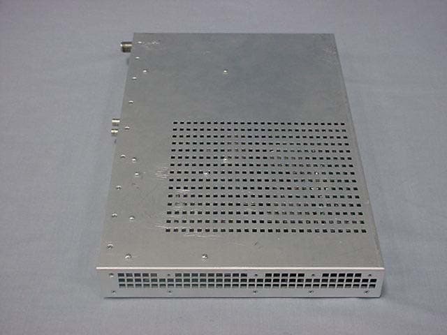
Click to zoom
Application Details
- Equipment Class
- NII - Unlicensed National Information Infrastructure TX
- Date of Grant
- Dec 18, 2002
- Application Purpose
- Original Equipment
- Date of Application
- Dec 18, 2002
- Equipment Note
- Unlicensed NII Transceiver
- Frequency Range
- 5741.50000000 - 5808.50000000
- Company
- Proxim Wireless Corporation
- Country
- United States
Documents & Files
Document Text
Text extracted from the exhibit documents filed with the FCC. Open a document above to read the original.
Users Manual
Lynx.GX Wireless Radios Tsunami Wireless Ethernet Bridges Installation and Maintenance CPN 62140 Issue Date: 12/01/02 Lynx.GX and Tsunami Radio Installation and Configuration Notices Copyright and Service Marks Copyright © 2002 by Proxim. All rights reserved. No part of this book may be reproduced without prior written permission from Proxim. The information contained in this book is subject to change without notice. Proxim shall not be liable for errors contained herein or for incidental or consequential damages in connection with the furnishing, performance, or use of this book or equipment supplied with this book. Proxim makes no warranty of any kind with regard to this book or any equipment supplied with this book, including, but not limited to, the implied warranties of merchantability and fitness for a particular purpose. Lynx™ is a trademark of Proxim Corporation. Tsunami™ is a trademark of Proxim Corporation. HELIAX® is a registered trademark of Andrews Corporation. OpenView® is a registered trademark of Hewlett Packard Corporation. SmartBits® is a registered trademark of Spirent Systems, Inc. Windows® is a registered trademark of Microsoft Corporation. Chariot® and Qcheck® are registered trademarks of NetIQ Corporation. Gabriel HE or HES parabolic antennas are products of Gabriel Electronics, Inc. Other names are trademarks of their respective owners. Y2K (Year 2000 Issue): All software supplied by and for Proxim products adhere to the 4-digit year nomenclature as required for Year 2000 compliance. Regulatory Notice This equipment has been tested and found to comply with the limits for a Class A digital device, pursuant to part 15 of the FCC Rules. These limits are designed to provide reasonable protection against harmful interference when the equipment is operated in a commercial environment. This equipment generates, uses, and can radiate radio frequency energy and, if not installed and used in accordance with the instruction manual, may cause harmful interference to radio communications. Operation of this equipment in a residential area is likely to cause harmful interference in which case the user will be required to correct the interference at his own expense. Shielded cables and I/O cords must be used for this equipment to comply wit the relevant FCC regulations. Changes or modifications not expressly approved in writing by Proxim may void the user’s authority to operate this equipment. Notices 2 CPN 62140 12/01/02 Lynx.GX and Tsunami Wireless Radio Installation and Maintenance This device complies with Part 15 of FCC rules and RSS-210 of Industry Canada. Operation is subject to the following two conditions: (1) this device may not cause interference, and (2) this device must accept any interference, including interference that may cause undesired operation of the device. This device must be installed professionally. Notices 3 CPN 62140 12/01/02 Lynx.GX and Tsunami Radio Installation and Configuration Contents NOTICES.........................................................................................................................................2 Copyright and Service Marks..........................................................................................................2 Regulatory Notice.........................................................................................................................2 CONTENTS.......................................................................................................................................4 ABOUT THIS BOOK..........................................................................................................................7 Intended Audience........................................................................................................................7 Support.......................................................................................................................................7 CHAPTER 1. INTRODUCTION..........................................................................................................8 Basic Equipment Features..............................................................................................................8 Lynx.GX Models......................................................................................................................9 Tsunami Models................................................................................................................... 10 Product Safety Instructions..........................................................................................................11 Grounding...........................................................................................................................13 CHAPTER 2. PLANNING FOR INSTALLATION................................................................................14 Selecting a Site..........................................................................................................................14 Line-of-Sight and Path Clearance Guidelines............................................................................14 Calculating Availability.................................................................................................................15 Calculating Received Signal Level and Link Budget..........................................................................15 Calculating Fade Margin...............................................................................................................16 Determining the Frequency Plan................................................................................................... 16 Planning for Antenna Installation..................................................................................................18 Reviewing the Installation Process................................................................................................ 20 1. Test radios back-to-back and configure.…
Text truncated - open the document above for the full version.
Attestation Statements
935 Stewart Drive, Sunnyvale, CA, USA94085 Tel (408) 731 2700, Fax (408)731 3675 STATEMENT THAT HZB-US5358-GX1 MUST BE PROFESSIONALLY INSTALLED AND SO IS EXEMPT FROM THE ANTENNA RESTRICTIONS OF FCC PART 15.203, INCLUDING INFORMATION ON ANTENNAS USED FOR TESTING This letter is submitted with regards to professional installation of the HZB-US5358-GX1 radios and the antennas used for testing. The HZB-U5358-GX1 radios must be professionally installed and so is exempt from the antenna restrictions of FCC Part 15.203. The HZB-U5358-GX1 is a group of products manufactured by Proxim Corporation in Sunnyvale, California. The HZB-U5358-GX1 is to be certified for operation under Part 15.247 and 15.407 of the FCC Rules in the 5.25-5.35 GHz, 5.725-5.825 GHz and 5.725-5.850 GHz bands. The equipment is designed for point-to-point communications and will carry data signals using T1/E1/DS3 or Ethernet interfaces. Due to the unique requirements of installation and integration of these systems, typical consumers or businesses will not have the proper training required for successful implementation of these systems. The HZB-U5358-GX1 is not designed for use by the general public, and will be sold as follows: • Through the Proxim sales force to professional communications users • Through designated and professionally trained Proxim Value Added Resellers to business users under individual reseller agreements. These companies will either use their professional telecommunications engineering staff to carry out the installation or will subcontract to professional installation firms. On occasion, a professional installation firm will purchase the HZB-U5358-GX1 radios directly. The HZB-U5358-G1X radio will be used for fixed, permanent or temporary, outdoor links requiring the use of directional antennas at 5 GHz band, which tend to be mounted on towers. These antennas will have narrow beam-widths and require professional installers to align them. In addition, the HZB-U5358-GX1 radio must be set up for the specific line interface required during installation. This procedure must be carried out by a qualified professional installer for the equipment to operate properly. The output power of the HZB-U5358-GX1 radio will be adjusted to meet any applicable EIRP limits by the professional installer during installation. The method of adjusting the output power is described in the manual written for use by professional trained installers. The HZB-U5358-GX1 radio is a full-duplex device with a common transmit/receive port. The addition of an external amplifier to boost the transmit power would disable the receive signal, thus rendering the HZB-U5358-GX1 radio inoperable. In addition, high power amplifiers (not generally available at 5.2-5.8 GHz) cannot be used without ensuring that signal saturation does not occur (because this would produce unrecoverable deterioration of the receive signal). Thus, a non-professional installer could not accomplish the addition of an amplifier. The HZB-U5358-GX1 radio is typically sold without an antenna, and the customer and/or installation engineer chooses from commercially available antennas. From time to time, Proxim may sell a commercially available antenna along with the HZB-U5358-GX1 radio upon customer request. Proxim has also included detailed instructions on how to determine the maximum output power based on EIRP limits for all professional installers to follow. Caroline Yu International Manager Proxim Corporation
Attestation Statements
935 Stewart Drive, Sunnyvale, CA, USA94085 Tel (408) 731 2700, Fax (408)731 3675 December 6, 2002 Subject: Statement of Compliance to FCC 15.407 (C) To Whom It May Concern: The HZB-US5358-GX1 radio was designed with networking capability, which demands the radio to carry networking traffic (polling, reporting) on a constant basis. Therefore, the radio is designed to transmit all the time (when operational). We designed the product in such a way that whenever a radio hardware failure is detected, the system firmware turns off the radio transmitter. Caroline Yu Homologation Manager Proxim Corporation 935 Stewart Drive, Sunnyvale, CA, USA94085 Tel (408) 731 2700, Fax (408)731 3675 Compliance with 15.407( g ) frequency stability for HZB-U5358-GX1 The transmitter frequency stability of the HZB-US5358-GX1 is controlled by two reference oscillators, one controls the 748 MHz transmit modulator, and one controls the transmit up converter LO frequency synthesizer (maximum LO operating frequency = 5.1 GHz). The two TCXOs are identical, and operate at a frequency of 10 MHz. The stability of the TCXO for temperature from –30 to + 70 o C and other instantaneous effects is ±4ppm maximum. The effects of ageing or long term stability is ±1 ppm per year. Therefore the overall stability of the transmitter is equal the maximum error produced in the transmit modulator plus the maximum error produced in the LO frequency synthesizer. Calculation: 748 MHz TX Modulator 5.1 GHz TX PLL Total Spec. TCXO Stability error in Hz error in Hz error in Hz Temp. ± 4 ppm2.99E+032.04E+042.34E+04 10 yrs. ± 10 ppm7.48E+035.10E+045.85E+04 Total@10yrs. 14 ppm1.05E+047.14E+048.19E+04 The maximum total error possible after ten years is +/- 82 KHz. a) For the 5.725-5.825 GHz band, the lowest channel center frequency is 5741.5 MHz, with a 26dBc bandwidth of 16.6 MHz. The margin below the 26dBc points to the band edge is 8.2 MHz. The highest channel center frequency is 5808.5 MHz with a 26dBc width of 16.5 MHz. The margin above 26dBc points to the band edge is 8.25 MHz. b) For the 5.25-5.35 GHz band, the lowest channel center frequency is 5274 MHz, with a 26dBc bandwidth of 32.5 MHz. The margin below the 26dBc points to the band edge is 7.75 MHz. The highest channel center frequency is 5326 MHz with a 26dBc width of 32.2 MHz. The margin above 26dBc points to the band edge is 7.9 MHz. c) Therefore, the frequency stability of the HZB-US5358-GX1 product ensures the compliance to 15.407(g). Caroline Yu Homologation Manager Proxim Corporation
Cover Letter(s)
935 Stewart Drive, Sunnyvale, CA, USA94085 Tel (408) 731 2700, Fax (408)731 3675 September 17, 2002 Federal Communications Commission Authorization and Evaluation Division Laboratory Division 7435 Oakland Mills Road Columbia, MD 21046 Re: Proxim Corporation, HZB-US5358-GX1 Request for withholding from public disclosure proprietary information submitted pursuant to applications for certification Dear Sir or Madam: Proxim Corporation requests that certain materials submitted with this application for certification of the HZB-U5358-GX1 radio be withheld from public disclosure. This request is made under the provision of Section 0.457 (d) of the Commission’s Rule and Section 552 (b) (4) of the Freedom of Information Act, Trade Secrets. The items marked “Confidential” contain detailed block diagrams, schematic diagrams, a parts list and a detailed theory of operation submitted to the FCC for review with this application. The information contains proprietary information (trade secrets) regarding the circuit operation and capabilities (specific values of components, circuit design details and system architecture), which are the result of our extensive investment in research and development. Without the disclosed information, competitive organizations would take considerable more time to assess and develop a workable competitive product. As a result, we believe that disclosure of these company guarded materials would compromise our leading position in this market. We therefore formally request that the materials marked “Confidential” be kept strictly confidential and not made available for inspection by any other party, except on a need to know basis for the sole purpose of the certification process. Caroline Yu Homologation Manager Proxim Corporation
Cover Letter(s)
From: David Chernomordik ITS/ES-Mpk Sent: Thursday, December 19, 2002 12:02 PM To: Roland Gubisch ITS/ES-Box Cc: Ollie Moyrong ITS/ES-Mpk Subject: RE: Proxim FCC ID: HZB-US5358-GX1 U-NII Hi Roland, The modulation used in the system is QPSK and the type of transmission is FDD. It is not TDD so the device transmits continuously. In this case, there is no significant difference in the results when using the regular averaging method (used in the past) and the new procedure. Actually, the only difference is in averaging in log scale (as used) and in linear scale (as required by the new procedure). I expecting a difference no more than a couple of dB. I can't estimate more precisely, sorry. David -----Original Message----- From: Roland Gubisch ITS/ES-Box Sent: Wednesday, December 18, 2002 12:47 PM To: David Chernomordik ITS/ES-Mpk; Ollie Moyrong ITS/ES-Mpk Subject: Proxim FCC ID: HZB-US5358-GX1 U-NII Importance: High Gentlemen: The DTS portion is fine. However, it is not clear if DA 02-2138 was used to provide the peak excursion data per 15.407(a)(6). Please comment. Thank you, Roland << File: U-NII Pk Tx Pwr DA-02-2138.pdf >>
Cover Letter(s)
935 Stewart Drive, Sunnyvale, CA, USA94085 Tel (408) 731 2700, Fax (408)731 3675 Attention: Steve Dayhoff, FCC Equipment Authorization Branch Correspondence Number: 6647 FCC ID: HZB-US5358-GX1 Applicant: Proxim Corporation 731 Confirmation Number: TC846252 Date of Original Email: 01/23/2003 Date of Response: February 6, 2003 Dear Mr Dayhoff: This is in response to your correspondence 6647. 1. The calculation in the originally submitted RF Exposure Statement was based on some simplified assumptions attempting to cover the worst-case exposure situation. To provide a more accurate calculation for more thorough coverage of various antenna types and sizes, I have included a more detailed calculation as attached. Please refer to this updated calculation for prove of compliance. 2. The diameter parameter published on Gabriel datasheet for panel antenna actually indicates the length of the side of the square shaped antenna. We verified this by taking measurement of the antenna we have. We will reflect to the manufacturer the inappropriate use of terminology, and hopeful they will correct it in the future. I hope this letter has addressed the questions you raised adequately. Please direct any further questions you may have to the undersigned. Yours truly, Caroline Yu Regulatory Compliance Manager Proxim Corporation
External Photos
External Photographs FCC ID: HZB-US5358-GX1 IC: 1856-U5358GX1 Indoor Unit FCC ID: HZB-US5358-GX1 IC: 1856-U5358GX1 Indoor Unit FCC ID: HZB-US5358-GX1 IC: 1856-U5358GX1 Indoor Unit FCC ID: HZB-US5358-GX1 IC: 1856-U5358GX1 Outdoor Unit FCC ID: HZB-US5358-GX1 IC: 1856-U5358GX1 Outdoor Unit FCC ID: HZB-US5358-GX1 IC: 1856-U5358GX1 Outdoor Unit FCC ID: HZB-US5358-GX1 IC: 1856-U5358GX1 Outdoor Unit
Internal Photos
Internal Photographs FCC ID: HZB-US5358-GX1 IC: 1856-U5358GX1 Indoor Unit FCC ID: HZB-US5358-GX1 IC: 1856-U5358GX1 Indoor Unit FCC ID: HZB-US5358-GX1 IC: 1856-U5358GX1 Indoor Unit FCC ID: HZB-US5358-GX1 IC: 1856-U5358GX1 Indoor Unit FCC ID: HZB-US5358-GX1 IC: 1856-U5358GX1 Indoor Unit FCC ID: HZB-US5358-GX1 IC: 1856-U5358GX1 Outdoor Unit FCC ID: HZB-US5358-GX1 IC: 1856-U5358GX1 Outdoor Unit FCC ID: HZB-US5358-GX1 IC: 1856-U5358GX1 Outdoor Unit FCC ID: HZB-US5358-GX1 IC: 1856-U5358GX1 Outdoor Unit FCC ID: HZB-US5358-GX1 IC: 1856-U5358GX1 Outdoor Unit FCC ID: HZB-US5358-GX1 IC: 1856-U5358GX1 Outdoor Unit
Operational Description
P.O. Box 70, Scarborough, Maine 04070 U.S.A. Tel: 207-883-5161Fax: 207-883-4469 email: [email protected]: http://www.gabrielnet.com 137 2 / 6 GHz Dual Band Electrical Specifications Associated Equipment InformationPages Point-to-Point Antenna Specifications................................. 14 - 111 Special Application Antennas.............................................135 - 145 Antenna Mounts & Reference Dimensions.......................112 - 134 Radomes................................................................................122 - 124 Tower Accessories.............................................................146 - 154 Transmission Lines..............................................................155 - 243 Dry Air Pressurizers............................................................244 - 253 5 GHz Directional Flat Panel Antenna Directional Flat Panels 5.250 - 5.850 GHz Directional Flat Panel Antenna 5 GHz - Spread Spectrum / NII Band Directional Flat Panel Antenna (for Point-to-Point applications) Facts & Features • Gabriel Quality and Dependability. • Lightweight and durable construction. • Quick and easy installation. • Feed input, Type N Female connector. (Other types available on request.) • Input connector positioned on back of antenna assembly. • Antenna supplied with paintable rigid radome. • All Gabriel antennas meet or exceed Standards EIA-195-C and EIA-222-F. • Antenna accommodates +/-20° elevation adjustment. (Specific installation limitations may apply.) • Mini-Mounts accommodate a 1.9 in. to 4.5 in. (48 to 114 mm) O.D. mast pipe. Quick-Align Mounts mount to a 2.375 in. (60 mm) O.D. mast pipe. An optional 1.9 in. (48 mm) to 4.5 in. (114 mm) Mast Clamp Kit is available on request for the Quick-Align Mount. • To adapt the Quick Align Mount for use on a 1.9 in. to 4.5 in. O.D. mast pipe order Mast Clamp Kit MCKQ-19-45 • Special colors and / or logos available on request. • Dual band models are available on request. Diagonal - Directional Flat Panel - Plane Polarized DFPS.5-52**0.5(0.15)MM17.518.0 18.419.030351.50(14.0) DFPD1-521(0.3)MM23.023.5 23.99.430431.50(14.0) DFPD1-52 (M1)1(0.3)QAM23.023.5 23.99.430431.50(14.0) DFPD2-522(0.6)QAM27.528.0 28.44.630461.50(14.0) NOTE: Product information subject to change without notice. Other polarization configurations available. 5.250 - 5.850 MM=Mini - Mount QAM=Quick Align Mount VSWR (R.L. max. dB) Frequency GHz Model Number Diameter ft (m) Mount Type Gain at Low Mid High dBi Nominal Mid-Band Beamwidth degrees XPD dB F/B ratio dB ** Note: The DFPS.5-52 antenna model is square in configuration. P.O. Box 70, Scarborough, Maine 04070 U.S.A. Tel: 207-883-5161Fax: 207-883-4469 email: [email protected]: http://www.gabrielnet.com 59 5.250 - 5.850 GHz Parabolic Antennas 5.250 - 5.850 GHz Facts & Features • Gabriel Quality and Dependability. • Innovative Feed Design. • Feed input is Type N Female, 50 ohm. • Isolation is 35 dB on Dual Polarized models. • Optional radomes available. • 2 ft. (0.6) model feeds are installed from the front of the antenna. 4 ft. (1.2), 6 ft. (1.8) and 8 ft. (2.4) model feeds are installed from the rear of the antenna, and allow for inspection or replacement from the rear. These models allow for smooth polarization adjustment from the back of the antenna. • Gabriel’s Quick Align Mount comes standard on the SSP2, SSD2 and HSSP2 models. This mount allows for quick installation and easy alignment of the antenna with two hand tools. The Quick Align Mount will mount to a 1.9 - 4.5 in OD mast pipe. • New environmentally pleasing neutral colors. • Dual band models are available. Electrical Specifications 5.250 - 5.850 Standard & High Performance Plane - Dual Polarized Unlicensed "NII" and Spread Spectrum / "ISM" Bands (National Information Infrastructure) (Industrial, Scientific & Medical) NOTE: †Improved VSWR available. Product information subject to change without notice. Gabriel "UNII" and "ISM" Band 2-ft. (0.6 m) - Plane Polarized - Standard Parabolic Antenna 5.250 - 5.850 Associated Equipment InformationPages Point-to-Point Antenna Specifications................................. 14 - 111 Special Application Antennas............................................135 - 145 Antenna Mounts & Reference Dimensions.......................112 - 134 Radomes..............................................................................122 - 124 Tower Accessories............................................................146 - 154 Transmission Lines.............................................................155 - 243 Dry Air Pressurizers...........................................................244 - 253 Size ft (m) VSWR (R.L. max. dB) Gain at Low Mid High dBi F/B ratio dB Standard Frequency GHz Model Number Nominal Mid-Band Beamwidth degrees XPD dB See the Special Application section of this catalog for Gabriel’s Directional Flat Panel antennas for Spread Spectrum operation. Standard - Plane Polarized SSP2-52B2(0.6)-28.128.5 29.06.125381.50(14.0)† SSP4-52A4(1.2)-33.634.2 34.63.130461.50(14.0)† SSP6-52A6(1.8)-37.037.5 38.02.130491.50(14.0)† SSP8-528(2.4)-39.439.8 40.31.630521.50(14.0)† Standard - Dual Polarized SSD2-52A2(0.6)-28.028.4 28.96.130381.50(14.0)† SSD4-524(1.2)-33.534.1 34.53.130461.50(14.0)† SSD6-526(1.8)-36.937.4 37.92.130491.50(14.0)† SSD8-528(2.4)-39.339.7 40.21.630521.50(14.0)† High Performance - Plane Polarized HSSP2-522(0.6)-27.728.1 28.66.130431.50(14.0)† HSSP4-524(1.2)-33.333.9 34.33.130501.50(14.0)† HSSP6-526(1.8)-36.737.2 37.72.130581.50(14.0)† HSSP8-528(2.4)-39.239.6 40.11.630621.50(14.0)† 050900 5.250 - 5.850 Antenna Typ e Manufacturer Model Numbe r Mid-band Gain (dBi) Notes 1 Foot Flat Panel Gabriel DFPD1-52 23.5 Andrew FPA5250D12-N 23.6 2 Foot Flat Panel Gabriel DFPD2-52 28 Andrew FPA5250D24-N 28.2 RSI A57A24-U 26.5 2 Foot Parabolic Gabriel SSP2-52B 28.5 Gabriel SSD2-52A 28.4 Gabriel HSSP2-52 28.1 Radio Waves SP2-5.2 28.3 Radio Waves SPD2-5.2 28.1 Andrew P2F-52 29.4 Andrew PX2F-52 29.4 R…
Text truncated - open the document above for the full version.
RF Exposure Info
935 Stewart Drive, Sunnyvale, CA, USA94085 Tel (408) 731 2700, Fax (408)731 3675 Attention: Reviewing Engineer The HZB-US5358-GX1 radio is designed for fixed-mount point-to-point applications. The maximum EIRP allowed to meet the power density limit of 1 mW/cm 2 (10 W/m 2 ) for General Population/ Uncontrolled Exposure as specified in rule 1.1310 can be calculated as below: With far field, the worst case is when power density is at the limit of 1mW/cm 2 at 1.5m away from the center of the antenna. The EIRP at the limit is: EIRP= 10 lg (S x 4πR 2 ) =10 log (10 x 12.56x 2.25) = 24.5 dBW = 54.5 dBm Where: S = Power density R = distance to the center of radiation of the antenna The near field power density is : S nf = 16ηP/π D 2 . The worst case of near-field power density is when the radio output at the maximum level of 316mW (25dBm), η=1, and antenna dimension is the smallest (1 foot panel, with 1.414 foot diagonal distance) S nf max = 16x0.316/π (1.414x0.3048) 2 = 8.7 W/m 2 = 0.87 mW/cm 2 <1 mW/cm 2 Where: S nf = maximum near –field power density P = power fed to the antenna η = aperture efficiency D = antenna diameter With the UNII models of the product family, when the maximum EIRP limits of +30dBm and 5.25-5.35 GH and +53dBm at 5.725-5.825GHz is observed, the .RF exposure level is in compliance with 1.1310. With the spread spectrum models of the product family, as long as the EIRP level does not exceed 54.5dBm, the RF exposure level is in compliance with 1.1310. If you should have any questions regarding this submission, please feel free to contact the undersigned. Yours truly, Caroline Yu Homologation Manager Proxim Corporation
RF Exposure Info
Power Density Calculation G (dB) D (m) A (m 2 ) P (W) S surface (w/m2) R nf (m) S nf (w/m 2 )R ff (m) S t max (w/m 2 )S ff (w/m 2 ) 1' Panel 23.5 0.4310 0.0929 0.316 13.6097 0.8978 8.6686 2.1547 5.1884 1.2132 2' Panel 28.0 0.8620 0.3715 0.316 3.4024 3.5912 2.1671 8.6188 2.1671 0.2137 2' parabolic 28.5 0.6096 0.2917 0.316 4.3330 1.7961 4.3330 4.3107 4.3330 0.9585 4' parabolic 34.0 1.2192 1.1669 0.316 1.0832 7.1845 1.0832 17.2428 1.0832 0.2126 6' parabolic 38.0 1.8288 2.6254 0.316 0.4814 16.1651 0.4814 38.7963 0.4814 0.1055 8' paraboli c 40.0 2.4384 4.6674 0.316 0.2708 28.7380 0.2708 68.9712 0.2708 0.0529 Where: G: antenna gainD: antenna diameter in meters, for panel antenna, D = 1.414x the side length of the antennaC: physical area of the aperture antennaP: radio output power, P max = 0.316 W A: physical area of the aperture antennaS surface : maximum power density at the antenna surface, S surface = 4P/A R nf : extent of near field, R nf = D 2 /4 λ , where λ is wavelength, at 5.8GHz, λ =0.052m S nf : maximum near field power density, S nf = 16 η P/ π D 2 ; for worst case situation, η is assmumed to be 1 R ff : distance to beginning of far field; R ff = 0.6D 2 / λ S t max : maximum powre density in the transition region; S t max =S nf *R nf /R min ; where R min = min (1.5m, R nf ) S ff : far field power density (on axis); S ff = PG/4 π R 2 Note: Power density beyond 1.5m from the center of antenna must be within 10W/m 2 or 1mW/cm 2 Created by: Caroline Yu 2/13/2003
Test Report
1365 Adams Court, Menlo Park, CA 94025 Proxim Corporation Date of Test: May 18 to August 20 2002 FCC ID: HZB-US5358-GX1 IC: 1856-U5358GX1 Report # 30276572 2 of 46 FCC Part 15 Subpart E TABLE OF CONTENTS 1.0 SUMMARY OF TESTS ................................................................................................................3 2.0 GENERAL DESCRIPTION ......................................................................................................... 4 2.1 Product Description ............................................................................................................4 2.2 Related Submittal(s) Grants ................................................................................................ 7 2.3 Test Methodology ...............................................................................................................7 2.4 Test Facility ........................................................................................................................ 7 3.0 SYSTEM TEST CONFIGURATION .......................................................................................... 8 3.1 Support Equipment and description.................................................................................... 8 3.2 Block Diagram of Test Setup.............................................................................................. 9 3.3 Justification ....................................................................................................................... 12 3.4 Software Exercise Program............................................................................................... 12 3.5 Mode of operation during test........................................................................................... 12 3.6 Modifications required for Compliance............................................................................ 12 3.7 Additions, deviations and exclusions from standards ....................................................... 12 4.0 MEASUREMENT RESULTS .................................................................................................... 13 4.1 Conducted Output Power at Antenna Terminal ................................................................ 13 4.2 26 dB Bandwidth .............................................................................................................. 14 4.3 Power Density...................................................................................................................22 4.4 The ratio of the peak excursion of the modulation envelope to the peak power .............. 30 4.5 Out-of-Band Conducted Emissions .................................................................................. 31 4.6 Transmitter Radiated Emissions ....................................................................................... 34 4.7 Radiated Emissions from Digital Section and Receiver ................................................... 36 4.8 AC Line Conducted Emission .......................................................................................... 43 4.9 Transmitter Duty Cycle Calculation / Measurements ....................................................... 45 5.0 LIST OF TEST EQUIPMENT ................................................................................................... 46 1365 Adams Court, Menlo Park, CA 94025 Proxim Corporation Date of Test: May 18 to August 20 2002 FCC ID: HZB-US5358-GX1 IC: 1856-U5358GX1 Report # 30276572 3 of 46 FCC Part 15 Subpart E 1.0 Summary of Tests FCC ID: HZB-US5358-GX1 IC: 1…
Text truncated - open the document above for the full version.
Contact Information
Applicant
Ken Lim(Accounting Manager)
Technical Contact
Intertek Testing ServicesDavid Chernomordik
[email protected]650-463-2900
1365 Adams Court · Menlo Park, California · United States
Non-Technical Contact
Intertek Testing ServicesDavid Chernomordik
[email protected]650-463-2900
Test Firm
Intertek Testing Services NA Inc.John Quigley
Technical Specifications
| # | Rule Parts | Frequency Range | Power Output |
|---|---|---|---|
| 2 | 15E | 5.74 GHz - 5.81 GHz | 309.00 mW |
Other Applications from Proxim Wireless Corporation
HZB-MEGA6
Aug 12, 2026EdgeAX 6GHz Radio Module
Equipment Class
6FC - 15E 6 GHz Fixed Client
HZB-GIGA5
Sep 21, 2023Startum X5 Gigabit 5 GHz Radio
Equipment Class
NII - Unlicensed National Information Infrastructure TX
HZB-NGPAP
Apr 26, 2021NGP LC 2.4 & 5 GHz Radios
Equipment Class
NII - Unlicensed National Information Infrastructure TX
HZB-NGPLC
Mar 04, 2021NGP LC 5 GHz Radio
Equipment Class
DTS - Digital Transmission System
HZB-NGP1058W
Nov 03, 2015802.11 ac PCIe Module
Equipment Class
DTS - Digital Transmission System