HZB-US58-S60Tsunami Subscriber Unit
Proxim Wireless Corporation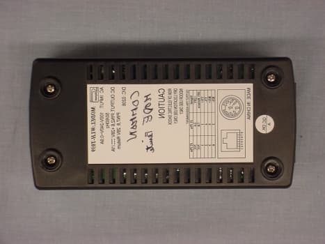
Click to zoom
Application Details
- Equipment Class
- NII - Unlicensed National Information Infrastructure TX
- Date of Grant
- May 08, 2002
- Application Purpose
- Original Equipment
- Date of Application
- May 08, 2002
- Equipment Note
- Tsunami Subscriber Unit
- Frequency Range
- 5740.00000000 - 5810.00000000
- Company
- Proxim Wireless Corporation
- Country
- United States
Documents & Files
Document Text
Text extracted from the exhibit documents filed with the FCC. Open a document above to read the original.
Users Manual
WESTERN MULTIPLEX CORPORATION Installation and Maintenance Manual Subscriber Unit Multipoint MAN 40XXX-001d1 SS TSUNAMI MULTIPOINT ii Revisions: September 2001 Draft October FCC submittal December Spread Spectrum Version WESTERN MULTIPLEX CORPORATION Tsunami Point-to-Multipoint 2001 Western Multiplex Corporation 1196 Borregas Avenue Sunnyvale, California 94089 USA Phone +1 408 542 5200 • Fax +1 408 542 5300 http://www.wmux.com ftp://ftp.wmux.com/products/ TSUNAMI MULTIPOINT ii NOTICE: CAREFULLY READ THE FOLLOWING LIMITED WARRANTY AND LIMITATION OF LIABILITY (THE “LIMITED WARRANTY”). BY USING THE WESTERN MULTIPLEX EQUIPMENT INCLUDED WITH THIS LIMITED WARRANTY, YOU AGREE TO THE TERMS AND CONDITIONS CONTAINED IN THIS LIMITED WARRANTY. IF YOU DO NOT AGREE TO THESE TERMS AND CONDITIONS, RETURN THE WESTERN MULTIPLEX EQUIPMENT TO WHERE IT WAS PURCHASED OR LEASED WITHIN THIRTY (30) DAYS OF RECEIPT FOR A FULL REFUND. 1. LIMITED EQUIPMENT WARRANTY 1.1 For the applicable Warranty Period (as defined in Paragraph 1.2 below) Western Multiplex warrants that the hardware manufactured by Western Multiplex and initially purchased or leased from one of Western Multiplex’s authorized resellers or distributors by the original end-user (“you”) for your personal use and not for resale (the “Equipment”) (a) substantially conforms to the specifications contained in the most recent version of the manual for the model of the Equipment purchased or leased by you (the “Equipment Specifications”) and (b) is free from defects in materials and workmanship. This Limited Warranty only applies to the Equipment and its preloaded firmware. This Limited Warranty does not apply to any software (or its associated documentation), whether preloaded with the Equipment, installed subsequently or otherwise (“Software”), nor does it apply to any firmware revision that is not originally preloaded on the Equipment at the time the Equipment is purchased or leased. The Software is licensed to you pursuant to the software license agreement that accompanied the Software and is subject to the terms, including the limited warranty and limitation of liability, contained in that license agreement. Western Multiplex has no obligation to repair or replace Software under this Limited Warranty. 1.2 This Limited Warranty shall start on the date that the Equipment is first shipped to you (the “Shipping Date”) and shall end: (a) for all unlicensed radio products which are point-to-multi-point products, one (1) year after the Shipping Date; (b) for all accessories, one (1) year after the Shipping Date; and (c) for all unlicensed radio products (except point-to-multi-point products) and for all licensed digital microwave radio products, two (2) years after the Shipping Date (in each case, the “Warranty Period”). 1.3 Nothing in this Limited Warranty affects any statutory rights of consumers that cannot be waived or limited by contract. 2. LIMITED WARRANTY EXCLUSIONS AND LIMITATIONS. 2.1 The Limited Warranty covers customary and intended usage only. 2.2 Western Multiplex does not warrant, and is not responsible for damage, defect or failure caused by any of the following: (a) Any part of the Equipment having been modified, adapted, repaired, or improperly installed, operated, maintained, stored, transported or relocated by any person other than Western Multiplex personnel or a Western Multiplex authorized service agent; (b) External causes, including electrical stress or lightning, interference caused by other radios or other sources, unsuitable physical or operating environment and use in conjunction with incompatible equipment or accessories; (c) Cosmetic damage, including all damage to the surface of the Equipment; iii (d) Acts of God, fires, floods, wars, terrorist acts, sabotage, civil unrest, labor disputes or similar events, actions or hazards; and (e) Accidents, negligence, neglect, mishandling, abuse or misuse, other than by Western Multiplex personnel or a Western Multiplex authorized service agent. 2.3 The Limited Warranty does not apply to the following parts of the Equipment, which are not manufactured by Western Multiplex, but which may be otherwise covered by an original manufacturer’s warranty: (a) antenna systems, including coaxial cable, wave guide, connectors, flex sections, mounts, and other parts of the antenna system and installation materials; (b) rack mounted equipment, which is not manufactured by Western Multiplex but which may be assembled, wired and tested at Western Multiplex’s factory or supplied as part of a system, including orderwire items, channel banks, multiplexers, fuse/alarm panels and remote alarm items; and (c) all equipment which is not included in Western Multiplex’s specifications. 2.4 Unless otherwise specified, equipment not manufactured by Western Multiplex is provided “AS IS” AND WITHOUT WARRANTIES OF ANY KIND. Please refer to the original manufacturer’s warranty, if any. 2.5 Any technical or other support provided for the Equipment by Western Multiplex, such as telephone assistance or assistance regarding installation, is provided “AS IS” AND WITHOUT WARRANTIES OF ANY KIND. 3. REPLACEMENT, REPAIR AND RETURN PROCESSES. 3.1 To request service under the Limited Warranty: (a) You must, within the applicable Warranty Period, promptly notify Western Multiplex of the problem with the Equipment, provide the serial number of the Equipment, and provide your contact information during business hours, by contacting Western Multiplex by telephone at 408-542-5390, by e-mail at [email protected], or by mail to Support, Western Multiplex Corporation, 1196 Borregas Avenue, Sunnyvale, California 94089, during the business hours of 8:00 a.m. to 5:00 p.m., Pacific Time, Monday through Friday, excluding holidays. This notice is effective when received by Western Multiplex during the business hours referenced above. (b) Western Multiplex shall, at its sole option, either resolve the problem over the telephone or provide you wi…
Text truncated - open the document above for the full version.
Attestation Statements
1365 Adams Court, Menlo Park, CA 94025 Proxim Corporation, Model No: 40100-XXX FCC ID: HZB-US58-S60Date of Test: September 20 to 23, 2001 10.0 Appendix D Western Multiplex Confidential 15.407(c) Compliance Sept. 17, 2001 page 1 Compliance to 15.407(c) HZB -US58-S60 The HZB -US58-S60 unit is a subscriber unit that operates in a point-to-multipoint network. It only transmits under the following conditions: a) The subscriber unit has received information at its Ethernet interface that is addressed to a destination accessible through the base station. The subscriber unit then transmits a reservation request to base station. The base station will respond with a time slot assignment, of finite duration, for the subscriber unit to transmit the data. b) The base station will periodically “poll” the subscriber units by requesting the subscriber unit to transmit a time slot of pseudorandom data. This is performed to maintain inbound synchronization and power control for each subscriber unit. c) The Control Processor in the subscriber unit only enables dc power to the transmitter circuitry if the following operational conditions are met: (i) The frequency synthesizers are locked. (ii) The subscriber unit receiver is operational and has correctly demodulated a valid control message from the base station during the previous 7.5-ms frame interval. (iii) The transmitter output power is below its allowable limit, as determined by coupling and detecting the output signal and comparing the detector output with a calibrated threshold voltage. (iv) The Control Processor is responding to interrupts as expected (checked by a watchdog timeout). (v) The modem, data buffer, and Ethernet interface is processing data without checksum or synchronization errors. Therefore, it is shown that the subscriber unit will automatically discontinue transmission in the absence of information to transmit or operational failure to ensure compliance with 15.407(c). Western Multiplex Confidential 15.407(g) Compliance Sept. 17, 2001 page 1 Compliance to 15.407(g) HZB -US58-S60 Emissions of the HZB -US58-S60 will be maintained within the band under all conditions of normal operation under the worst case of frequency shift. As described in the theory of operations document, the frequency of the RF signal is completely determined by a single reference oscillator of 20.75MHz frequency. Two vendors have been approved to supply the reference oscillator, part #690-00173-06, and the frequency-stability characteristics of each vendor’s part are shown in the following table. Data sheets are attached for reference. Frequency-Stability Characteristics of Reference Oscillator (p/n 690-00173-06) Characteristic Vectron [email protected] Rakon VTXO220U-20.75MHz Type TCXO TCXO Initial Calibration ±2 ppm ±5 ppm Stability vs.Temperature (-33°C to +70°C) ±2 ±2 Stability vs. Supply Voltage ±0.3 ±0.3 Aging (7years) ±5 ±5 Total: ±9.3 ppm ±12.3 ppm The worst-case stability is ±12.3 ppm, or ±72 kHz, over all operating conditions. This is sufficient to maintain the emissions within the allowable band; the supporting reasoning for this claim is as follows: a) The lowest channel center frequency is 5740.40MHz, with a maximum 26dBc bandwidth of 26MHz. The margin from the lower band edge of 5.725GHz to the lower 26dBc point is 2.4MHz. This margin is greater than the maximum oscillator error of 130kHz. b) The highest channel center frequency is 5809.57MHz, with a maximum 26dBc bandwidth of 26MHz. The margin from the upper band edge of 5.825GHz to the upper 26dBc point is 2.43MHz. This margin is also greater than the maximum oscillator error of 130kHz. Therefore, it is determined that the frequency-determining components offer superior stability to ensure compliance with 15.407(g). MODEL VTXO200U SMD Voltage Controlled Temperature Compensated Crystal Oscillators Small SMD TCXO with standard 4-terminal interface available in custom frequencies ranging from 8.2MHz to 32MHz with a clipped sinewave output. Product Description This Colpitts oscillator uses the direct two-port temperature compensation method. Operating on the fundamental mode, the circular AT-cut crystal is housed in the environmentally rugged UM-1 SLIM resistance weld package. The product can be configured to operate on any voltage between 2.7V and 5V. A mechanical trimmer is available for adjusting the frequency. Customized frequencies readily available make this model suitable for many timing and frequency applications. Applications include GPS, TDMA/APMS/CDMA cellular and satellite phones, PCMCIA CDPD cards, two-way pagers and many other wireless possibilities. Features Uses the high performance UM-1 slim crystal Excellent phase noise performance, very little aging and low temperature hysteresis under high vibration environments Clipped sinewave frequency output (8.2MHz to 32MHz) Standard temperature stability choices are +/-1ppm, +/-1.5ppm and +/-2.5ppm, over wide temperature range This product has no trimmer to allow for an aqueous wash process Non-standard frequencies available on quick turn around Frequency control ranges from 6 to 50ppm available 1.0 SPECIFICATION REFERENCES 1.1 Model Description VTXO220U 20.75 MHz 1.2 Reference Number 1133 1.3 Company WirelessHome 1.4 Rakon Internal Part No. TX2046 2.0 FREQUENCY CHARACTERISTICS Line Parameter Test Condition Min.Max. Units 2.1 Nominal Frequency Nominal Frequency referenced to 25 deg. C. 20.75MHz 2.2 Frequency calibration Frequency at 23 deg. C +/-2 deg. C (see Note 1) 3.0 +/-ppm 2.3 Frequency stability over temperature Referenced to frequency reading at 25 deg. C. Temperature varied at max. of 2 deg. C per minute. Control voltage varied between min. and max. (Note 2) 2.0 +/-ppm 2.4 Temperature range The operating temperature range over which the frequency stability is measured (Note 3) -30.075.0 Degrees C 2.5 Frequency perturbations Peak to peak amplitude of frequency perturbation within operating temperature range (Note 1) 0.5 ppm 2.6 Frequency …
Text truncated - open the document above for the full version.
Cover Letter(s)
April 16, 2002 Federal Communications Commission Authorization and Evaluation Division Laboratory Division 7435 Oakland Mills Road Columbia, MD 21046 Re: Request for withholding from public disclosure proprietary information FCC ID: HZB -US58-S60 Dear Sir or Madam: Western Multiplex Corporation requests that certain materials submitted with this application for certification of the Tsunami Multipoint Radio be withheld from public disclosure. This request is made under the provision of Section 0.457 (d) of the Commission’s Rule and Section 552 (b) (4) of the Freedom of Information Act, Trade Secrets. The items marked “Confidential” contain detailed block diagrams, schematic diagrams, antenna design specifications, a parts list and a detailed theory of operation submitted to the FCC for review with this application. The information contains proprietary information (trade secrets) regarding the circuit operation and capabilities (specific values of components, circuit design details and system architecture), which are the result of our extensive investment in research and development. Without the disclosed information, competitive organizations would take considerable more time to assess and develop a workable competitive product. As a result, we believe that disclosure of these company guarded materials would compromise our leading position in this market. We therefore formally request that the materials marked “Confidential” be kept strictly confidential and not made available for inspection by any other party, except on a need to know basis for the sole purpose of the certification process. Caroline Yu Homologation Product Manager Proxim Corporation 1196 Borregas Ave., Sunnyvale, CA 94089-1302, USA Tel: +1 (408) 542-5200, Fax: +1 (408) 542-5300
External Photos
FCC ID: HZB-US58-S60 ODU FCC ID: HZB-US58-S60 ODU HZB-US58-S60 IDU HZB-US58-S60 IDU HZB-US58-S60 IDU
ID Label/Location Info
Label Location
Internal Photos
FCC ID: HZB-US58-S60 ODU FCC ID: HZB-US58-S60 ODU FCC ID: HZB-US58-S60 ODU FCC ID: HZB-US58-S60 ODU FCC ID: HZB-US58-S60 ODU FCC ID: HZB-US58-S60 ODU FCC ID: HZB-US58-S60 ODU FCC ID: HZB-US58-S60 ODU FCC ID: HZB-US58-S60 ODU FCC ID: HZB-US58-S60 ODU FCC ID: HZB-US58-S60 Antenna FCC ID: HZB-US58-S60 FCC ID: HZB-US58-S60 IDU FCC ID: HZB-US58-S60 IDU FCC ID: HZB-US58-S60 IDU
RF Exposure Info
Attention: Reviewing Engineer The HZB-US58-S60 radio is designed for fixed-mount point-to-point applications. The device is integrated to an array antenna with maximum gain of 21dBi. The maximum EIRP for the HZB-US58-S60 as defined in FCC 15.407 is +53 dBm. For the worst case EIRP of +53dBm, the power density at 1.5 meters from an antenna is: S = EIRP/4πR 2 =7.1 W/m 2 =0.71 mW/cm 2 < 1 mW/cm 2 Where: S = Power density R = distance to the center of radiation of the antenna Therefore, the power density is compliant with the limit for General Population/ Uncontrolled Exposure as specified in rule 1.1310. If you should have any questions regarding this submission, please feel free to contact the undersigned. Yours truly, Caroline Yu Homologation Product Manager Proxim Corporation 1196 Borregas Ave., Sunnyvale, CA 94089-1302, USA Tel: +1 (408) 542-5200, Fax: +1 (408) 542-5300
Test Report
Intertek Testing Services ETL SEMKO for Proxim Corporation Job # 3008928 Date of Test: September 20 to 23, 2001 Total No ofPages contained in this Report:2l Test Report #: 30089281 Date of Report: September 25,2001 Revised: February 26, 2002 Revised: April 20, 2002 w=ey NVLAP Laboratory Code 20020 1-0 ..1I.i;;... ~@ .:J)a.J/t~ ~J1It-O~ ;z David Chemomordik, EMC Technical Manager , Review Date: ~ e.-n: ~- Intertek Testing Services NA, Inc. 1365 Adams Court, Menlo Park, CA 94025 Telephone 650-463-2900 Fax 650-463-2910 Home Page www.etlsemko.com on the Tsunami Subscriber Unit Model: 40100-XXX FCC ID: HZB-US58-S60 1365 Adams Court, Menlo Park, CA 94025 Proxim Corporation, Model No: 40100-XXX FCC ID: HZB-US58-S60Date of Test: September 20 to 23, 2001 Report # 30089281FCC Part 15.407 U-NII Page 2 of 51 TABLE OF CONTENTS 1.0Summary of Tests.......................................................................................................................3 2.0General Description....................................................................................................................4 2.1Product Description.........................................................................................................4 2.2Related Submittal(s) Grants..............................................................................................5 2.3Test Methodology............................................................................................................5 2.4Test Facility....................................................................................................................5 3.0System Test Configuration..........................................................................................................6 3.1Support Equipment and description...................................................................................6 3.2Block Diagram of Test Setup............................................................................................6 3.3Justification.....................................................................................................................7 3.4Software Exercise Program...............................................................................................7 3.5Mode of operation during test...........................................................................................7 3.6Modifications required for Compliance..............................................................................7 3.7Additions, deviations and exclusions from standards..........................................................7 4.0Measurement Results..................................................................................................................8 4.1Conducted Output Power at Antenna Terminal...................................................................8 4.226 dB Bandwidth.............................................................................................................9 4.3Power Density...............................................................................................................14 4.4The ratio of the peak excursion of the modulation envelope to the peak power...................28 4.5Out-of-Band Conducted Emissions..................................................................................37 4.6Radiated Emissions........................................................................................................39 4.7AC Line Conducted Emission.........................................................................................45 5.0List of Test Equipment.............................................................................................................50 6.0Document History.....................................................................................................................51 7.0Appendix A...............................................................................................................................51 8.0Appendix B...............................................................................................................................51 9.0Appendix C...............................................................................................................................51 10.0Appendix D...............................................................................................................................51 1365 Adams Court, Menlo Park, CA 94025 Proxim Corporation, Model No: 40100-XXX FCC ID: HZB-US58-S60Date of Test: September 20 to 23, 2001 Report # 30089281FCC Part 15.407 U-NII Page 3 of 51 1.0Summary of Tests Proxim Corporation, Tsunami Subscriber Unit, Model: 40100-XXX FCC ID: HZB-US58-S60 TestReferenceResults Output power15.407(a)Complies, see sec. 4.1 of this report 26 dB Bandwidth15.407(a)For calculation only, see sec. 4.2 of this report Power Density15.407(a)(5)Complies, see sec. 4.3 of this report The ratio of the peak excursion of the modulation envelope to the peak transmit power 15.407(a)(6)Complies, see sec. 4.4 of this report Out-of-band Antenna Conducted Emission15.407(b)Complies, see sec. 4.5 of this report Spurious Radiated Emission from transmitter15.407(b)Complies, see sec. 4.6 of this report Radiated Emission in Restricted Bands15.209, 15.205Complies, see sec. 4.6 of this report Radiated Emission from digital part and receiver15.109Complies, see sec. 4.6 of this report AC Conducted Emission15.207Complies, see sec. 4.7 of this report Requirement15.407(c)Complies, see file " Appendix D" Requirement15.407(g)Complies, see file " Appendix D" Radiation Exposure Requirement1.1310Complies, see file "RF Exposure Statement" Antenna Requirement15.203Complies, the EUT uses a permanently connected antenna 1365 Adams Court, Menlo Park, CA 94025 Proxim Corporation, Model No: 40100-XXX FCC ID: HZB-US58-S60Date of Test: September 20 to 23, 2001 Report # 30089281FCC Part 15.407 U-NII Page 4 of 51 2.0General Description 2.…
Text truncated - open the document above for the full version.
Test Report
Appendix A Plots 15.407((b), Out-of-Band emissions 4.a.1 – 4.a.8Ch 0QAM16 4.b.1 – 4.b.8Ch 2QAM16 4.c.1 – 4.c.9Ch 5QAM16
Test Report
Appendix B Plots 15.407((b), Out-of-Band emissions 4.d.1 – 4.d.8CH 0QAM8 4.e.1 – 4.e.7CH 2QAM8 4.f.1 – 4.f.10Ch 5QAM8
Test Report
Appendix C Plots 15.407((b), Out-of-Band emissions 4.g.1 – 4.g.10Ch 0QPSK R ¾ 4.h.1 – 4.h.7Ch 2QPSK R ¾ 4.i.1 – 4.i.11Ch 5QPSK R ¾
Test Setup Photos
Setup Configuration Photograph HZB-US58-S60 Radiated emission test Radiated emission test AC Line conducted emission test
Contact Information
Applicant
Ken Lim(Accounting Manager)
Technical Contact
Intertek Testing ServicesDavid Chernomordik
[email protected]650-463-2900
1365 Adams Court · Menlo Park, California · United States
Non-Technical Contact
Intertek Testing ServicesStephenie Smith
[email protected]650-463-2900
Test Firm
Intertek Testing Services NA Inc.John Quigley
Technical Specifications
| # | Rule Parts | Frequency Range | Power Output |
|---|---|---|---|
| 1 | 15E | 5.74 GHz - 5.81 GHz | 63.00 mW |
Other Applications from Proxim Wireless Corporation
HZB-MEGA6
Aug 12, 2026EdgeAX 6GHz Radio Module
Equipment Class
6FC - 15E 6 GHz Fixed Client
HZB-GIGA5
Sep 21, 2023Startum X5 Gigabit 5 GHz Radio
Equipment Class
NII - Unlicensed National Information Infrastructure TX
HZB-NGPAP
Apr 26, 2021NGP LC 2.4 & 5 GHz Radios
Equipment Class
NII - Unlicensed National Information Infrastructure TX
HZB-NGPLC
Mar 04, 2021NGP LC 5 GHz Radio
Equipment Class
DTS - Digital Transmission System
HZB-NGP1058W
Nov 03, 2015802.11 ac PCIe Module
Equipment Class
DTS - Digital Transmission System