HZBLYNX96Direct Sequence Spread Spectrum Radio
Proxim Wireless Corporation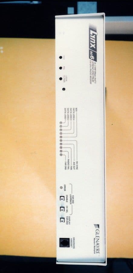
Click to zoom
Application Details
- Equipment Class
- DSS - Part 15 Spread Spectrum Transmitter
- Date of Grant
- Apr 07, 1999
- Application Purpose
- Original Equipment
- Date of Application
- Feb 18, 1999
- Equipment Note
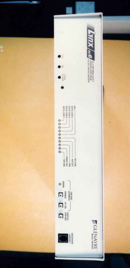
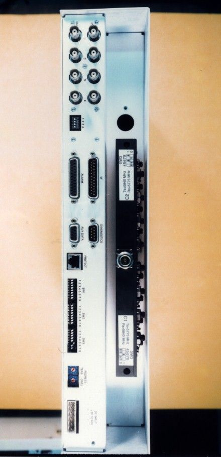
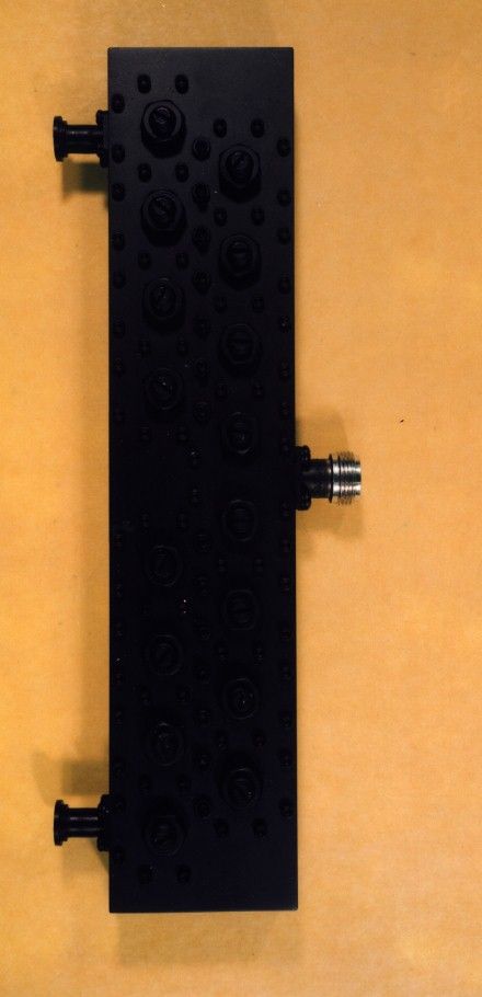
- Direct Sequence Spread Spectrum Radio
- Frequency Range
- 5735.00000000 - 5840.00000000
- Company
- Proxim Wireless Corporation
- Country
- United States
Documents & Files
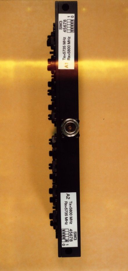
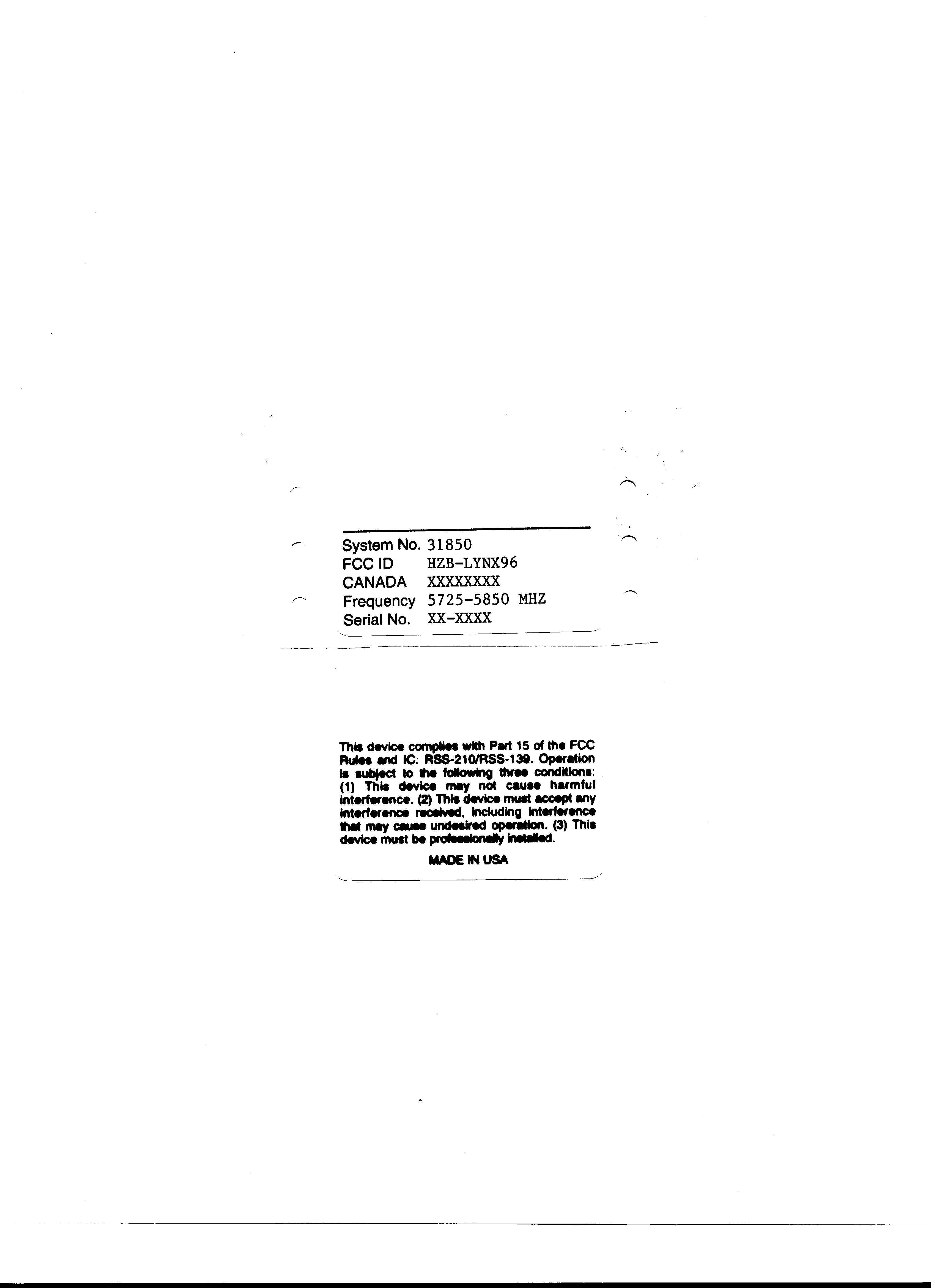
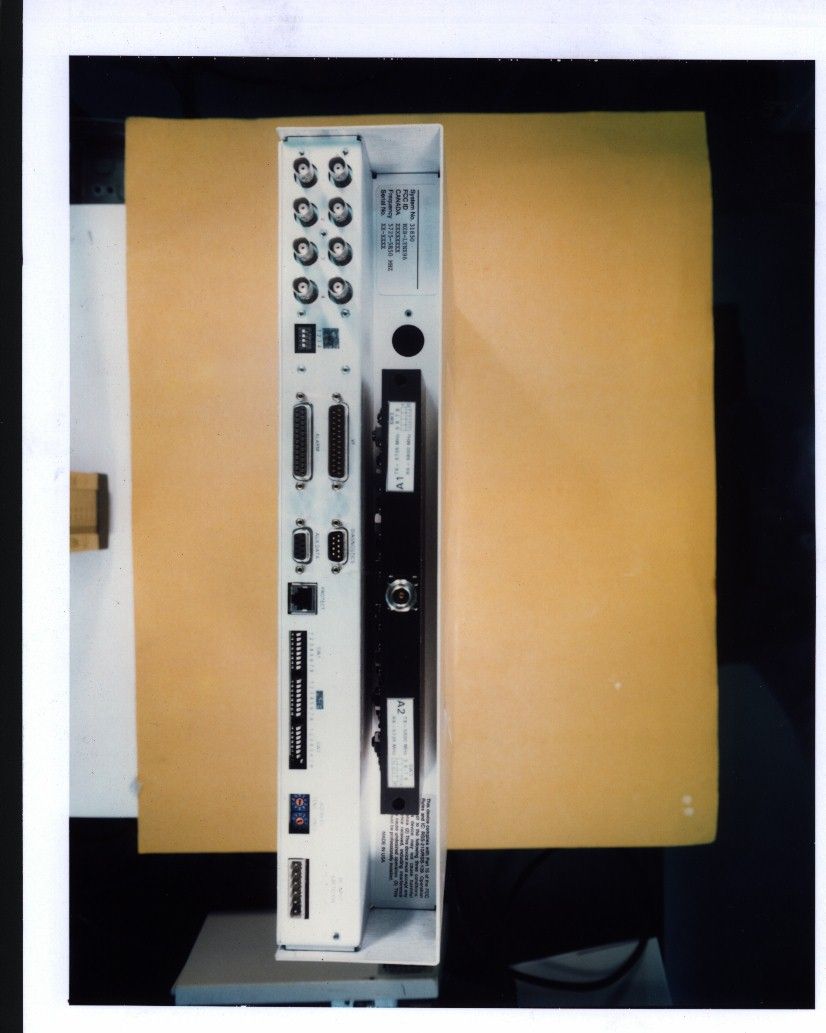
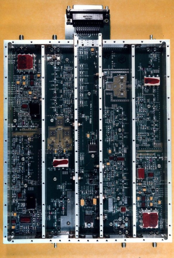
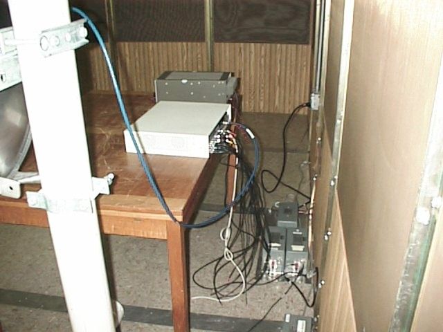
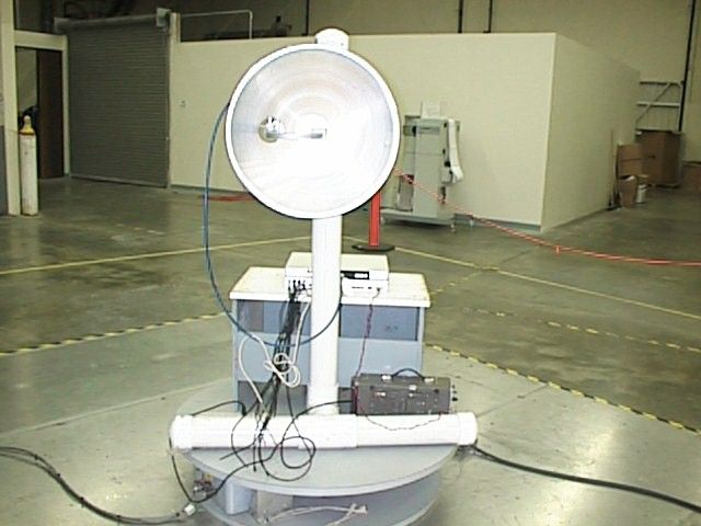
Document Text
Text extracted from the exhibit documents filed with the FCC. Open a document above to read the original.
Users Manual
INSTALLATION AND MAINTENANCE MANUAL 1xE1, 2xE1 AND 4xE1 (2.048 Mbps) SPREAD SPRECTRUM RADIOS (2.4 AND 5.8 GHz) INSTALLATION AND MAINTENANCE MANUAL LYNX.sc E1 FAMILY SPREAD SPECTRUM RADIOS OCTOBER 1998 i Installation and Maintenance Manual Copyright © 1998 by Glenayre Western Multiplex. All rights reserved. No part of this manual may be reproduced without prior written permission from Glenayre Western Multiplex. The information contained in this manual is subject to change without notice. Glenayre Western Multiplex shall not be liable for errors contained herein or for incidental or consequential damages in connection with the furnishing, performance, or use of this manual or equipment supplied with this manual. Glenayre Western Multiplex makes no warranty of any kind with regard to this manual or any equipment supplied with this manual, including, but not limited to, the implied warranties of merchantability and fitness for a particular purpose. Heliax is a registered product of Andrews Corporation. Fireberd is a registered product of Telecommunications Techniques Corporation. Printed in the United States of America Notice: Y2K (Year 2000 Issue) All software supplied by and for Glenayre Western Multiplex products adheres to the four- (4) digit year nomenclature as required for Year 2000 compliance. Glenayre Western Multiplex 1196 Borregas Avenue Sunnyvale, California USA Tel:+1 408 542-5200 Fax:: +1 408 542-5300 Our facility has been Registered to the International Organization for Standardization ISO 9000 Series Standards for quality. Issue: October 1998 INSTALLATION AND MAINTENANCE MANUAL LYNX.sc E1 FAMILY SPREAD SPECTRUM RADIOS OCTOBER 1998 ii This page intentionally left blank INSTALLATION AND MAINTENANCE MANUAL LYNX.sc E1 FAMILY SPREAD SPECTRUM RADIOS OCTOBER 1998 iii Regulatory Notice This equipment has been tested and found to comply with the limits for a class B digital device, pursuant to Part 15 of the FCC Rules. These limits are designed to provide reasonable protection against harmful interference in a residential installation. This equipment generates, uses and can radiate radio frequency energy and, if not installed and used in accordance with the instructions, may cause harmful interference to radio communications. However, there is no guarantee that interference will not occur in a particular installation. If this equipment does cause harmful interference to radio or television reception, which can be determined by turning the equipment off and on, the user is encouraged to try to correct the interference by one or more of the following measures: *Reorient or relocate the receiving antenna. *Increase the separation between the equipment and receiver. *Connect the equipment into an outlet on a circuit different from that to which the receiver is connected. *Consult the dealer or an experienced radio/TV technician for help. Shielded cables and I/O cords must be used for this equipment to comply with the relevant FCC regulations. Changes or modifications not expressly approved in writing by Glenayre Western Multiplex may void the user's authority to operate this equipment. This device complies with RSS-210 and/or RSS-139 of Industry Canada. Operation is subject to the following two conditions: (1) this device may not cause interference, and (2) this device must accept any interference, including interference that may cause undesired operation of the device. This device must be professionally installed. INSTALLATION AND MAINTENANCE MANUAL LYNX.sc E1 FAMILY SPREAD SPECTRUM RADIOS OCTOBER 1998 iv This page intentionally left blank INSTALLATION AND MAINTENANCE MANUAL LYNX.sc E1 FAMILY SPREAD SPECTRUM RADIOS OCTOBER 1998 vW/CS97-1 GENERAL TERMS 1.1 All Definitions contained in Glenayre Western Multiplex's Conditions of Sale (Glenayre Western Multiplex document number CS96-8), apply to the Warranty. 1.2 Subject to the provisions of the Warranty, Glenayre Western Multiplex warrants that the equipment described in Paragraph 1.3 shall conform to their specifications described in Paragraph 1.4 in all material respects and that the equipment shall be free from material defects in materials and workmanship. 1.3 This Warranty applies to all original purchases of Glenayre Western Multiplex manufactured equipment and accessories (collectively the "Equipment"). 1.4 This Warranty applies to the specifications contained in the most recent version of the manual for the model of the Equipment purchased (the "Specifications"). 1.5 This Warranty does not apply to the following items of Equipment which are covered by the Original Equipment Manufacturer's warranty: (a) antenna systems, including coax cable, waveguide, connectors flex-sections, mounts, other parts of the antenna system and installation materials; (b) non-Glenayre Western Multiplex manufactured rack mounted equipment that is assembled wired and tested at Glenayre Western Multiplex's factory or supplied as part of a system, including orderwire items, channel banks, multiplexers, fuse/alarm panels, remote alarm items; and (c) equipment which is not listed in Glenayre Western Multiplex's price book. 1.6 The effective period of this Warranty shall start on the date of shipment of the Equipment and shall end: (a) for all spread spectrum unlicensed radio products and for all licensed digital microwave radio products, two (2) years later; (b) for all analog microwave radio products, three (3) years later; or (c) for all baseband products, five (5) years later (in each case the "Warranty Period"). 1.7 The Customer acknowledges that Glenayre Western Multiplex does not represent or warrant that the services provided by Glenayre Western Multiplex under this Warranty will ensure uninterrupted or error-free operation of the Equipment. RETURN OF EQUIPMENT UNDER WARRANTY 2.1If an item of Equipment malfunctions or fails in normal intended usage and maintenance within the applicable Warranty Period: (a) the Customer shall promptly notify Glenayre We…
Text truncated - open the document above for the full version.
Cover Letter(s)
Western Multiplex 1196 Borregas Ave Sunnyvale, CA 94089 USA tel 408 542 5200 fax 408 542 5300 www Wlrelesslnterconnect corn 13 November 1998 Federal Communications Commission Authorization and Evaluation Division 7435 Oakland Mills Road Columbia, MD 2 1046 We, the undersigned, hereby authorize Intertek Testing Services to act on our behalf in all matters relating to applications for equipment authorization, including the signing of all documents relating to these matters. Any and all acts carried out by Intertek Testing Services on our behalf shall have the same effect as acts of our own. We also hereby certify that no party to the applications authorized hereunder is subject to a denial of benefits, that includes FCC benefits, pursuant to Section 5301 of the Anti-Drug Abuse Act of 1988,21 U.S.C. 853 (a). This agreement expires one year from the current date. Director, Product Management Communication InnovationsTM
Cover Letter(s)
Western Multiplex 1196 Borregas Ave. Sunnyvale, CA 94089 USA tel 408 542 5200 fax 408 542 5300 www.Wirelesslnterconnect.com EGLENAYRE’” 13 November 1998 Federal Communications Commission Authorization and Evaluation Division Laboratory Division 7435 Oakland Mills Road Columbia, MD 2 1046 Re: Glenayre Western Multiplex, Model LYNX.sc6 (4E) Request for withholding from public disclosure proprietary information submitted pursuant to an application for certification of a Spread Spectrum transmitter. FCC ID: HZB-LYNX96 Dear Sir or Madam: Glenayre Western Multiplex requests that certain materials submitted with this application for certification of the Model LYNX.sc6 (4E) Spread Spectrum El Radio Modem be withheld from public disclosure. This request is made under the provision of Section 0.457 (d) of the Commission’s Rule and Section 552 (b) (4) of the Freedom of Information Act, Trade Secrets. The items marked “Confidential” contain detailed block diagrams, schematic diagrams, and a detailed theory of operation submitted to the FCC for review with this application. The information in this envelope contains proprietary information (trade secrets) regarding the circuit operation and capabilities (specific values of components, circuit design details and system architecture) which are the result of our extensive investment in research and development. Without the disclosed information, competitive organizations would take considerable more time to assess and develop a workable competitive product. As a result, we believe that disclosure of these company guarded materials would compromise our leading position in this market. We therefore formally request that the materials contained in this envelope be kept strictly confidential and not made available for inspection by any other party, except on a need to know basis for the sole purpose of the certification process. Director, Prb/duct Management Communlcatlon Innovations.TM
Cover Letter(s)
EGLENAYRE’” Western Multiplex 1196 Borregas Ave. Sunnyvale, CA 94089 USA tel 408 542 5200 fax 408 542 5300 www.Wirelesslnterconnect.com 13 November 1998 Federal Communications Commission Authorization and Evaluation Division 7435 Oakland Mills Road Columbia, MD 2 1046 Attention: Reviewing Engineer The user’s manual supplied in this application is written to include several models of LYNX.sc radios, many of which have already been certified, to include the radio submitted here. The unit which is being submitted here is the 5.8 GHz, quadruple El capacity radio (the LYNX.sc6 (4E), model number 31850). As certifications are obtained, the appropriate regulatory information in the manual is edited. When this manual is released for customers, an appropriate statement will be made in the regulatory information cover sheet indicating which models comply with which FCC and IC rule parts and their appropriate certification numbers provided in Section 2 of the manual. If you have any questions regarding this submission, please feel free to contact the undersigned. Director, Product Management Communlcatlon InnovationsTM
Cover Letter(s)
Western Multiplex 1196 Borregas Ave. Sunnyvale, CA 94089 USA tel 408 542 5200 fax 408 542 5300 www.Wirelesslnterconnect.com EGLENAYRE’” 13 November 1998 Intertek Testing Services 1365 Adams Ct. Menlo Park, CA 94025 STATEMENT THAT LYNX.sc6 (4E) MUST BE PROFESSIONALLY INSTALLED AND SO IS EXEMPT FROM THE ANTENNA RESTRICTIONS OF FCC PART 15.203, INCLUDING INFORMATION ON ANTENNAS USED FOR TESTING This letter is submitted with regards to professional installation of the LYNX.sc6 (4E) radio and the antennas used for testing. The LYNX.sc6 (4E) radio must be professionally installed and so is exempt from the antenna restrictions of FCC Part 15.203. The LYNXsc6 (4E) is a product manufactured by Glenayre Western Multiplex in Sunnyvale, California. The LYNX.sc6 (4E) is a spread spectrum device, to be certified for operation under Part 15.247 of the FCC Rules in the 5725-5850 MHz band. This equipment is designed for point-to-point communications and will only carry four CEPT- 1 signals. The CEPT- 1 signals have telecommunications interfaces which are only provided by professional telecommunications equipment (such as a CSU/DSU or multiplexer). General user-oriented equipment does not provide these interfaces and cannot be easily installed with the LYNX.sc6 (4E). The LYNX.sc6 (4E) is not designed for use by the general public, and will be sold as follows: l either through the Glenayre Western Multiplex sales force to professional communications users in the following categories : electric power utilities, cellular telephone operating companies, personal communication service operating companies, regional Bell operating companies, oil and gas exploration and transmission companies, railroad companies, federal, state and local government agencies, or lthrough designated and professionally trained Glenayre Western Multiplex Value Added Resellers (VARs) to business users under individual reseller agreements. These companies will either use their professional telecommunications engineering staff to carry out the installation or will subcontract to professional installation firms. On occasion, a professional installation firm will purchase the LYNX.sc6 (4E) radios directly. The LYNX.sc6 (4E) will be used for fixed, permanent or temporary, outdoor links requiring the use of directional antennas at 5.8 GHz which tend to be mounted on towers. These antennas will be 2 ’,4 ’ ,6 ’or 8 ’dishes which have narrow beamwidths (ranging from 7 degrees to less than 2 degrees) and require professional installers to align them. Communication Innovations.TM
Cover Letter(s)
In addition, the LYNX.sc6 (4E> installation. This procedure must becan-ledoutby a quahtied professionalinstaller for the equipment to operate properly. The output power of the LYNX.sc6 (4E) radio will be adjusted to meet any applicable EIRI limits by the professional installer during installation. The method of adjusting the output power is described in the manual written for use by professional trained installers. The LYNX.sc6 (4E) is a full duplex device with a common transmit and receive port. The addition of an external amplifier to boost the transmit power would disable the receive signal, thus rendering the LYNX.sc6 (4E) inoperable. In addition, high power amplifiers (not generally available at 5.8 GHz) cannot be used without ensuring that signal saturation does not occur (because this would produce unrecoverable deterioration of the receive signal). Thus, the addition of an amplifier could not be accomplished by a non-professional installer. I The LYNX.sc6 (4E) is typically sold without an antenna, and the customer and/or installation engineer chooses from commercially available antennas. From time to time, Glenayre Western I Multiplex may sell a commercially available antenna along with the LYNX.sc6 (4E) upon customer request.% Prior to testing of the LYNX.sc series of radios, Greg Czumak and Ed Gibbons of the Federal Communications Commission reviewed a list of commercially available antennas, which Glenayre Western Multiplex provided, for the purposes of determining which antenna would be appropriate for compliance testing. The Comsat RSI Mark Antenna Model #P-57C24N-1 was chosen for the LYNX.sc6 (4E) test as it is a reasonable representation of a typical antenna that would be used with this radio. Evaluation of the results with this antenna can be easily 1 Ken Kuppel WY -
Test Report
Intertek Testing Services APPLICATION FOR FCC CERTIFICATION Glenayre Western Multiplex Spread Spectrum Radio Model: 31850 FCC ID: HZB-LYNX96 Job # J98027347 Number of Pages: 14 pp. + Supporting Data and Documents Date of Report: October 16, 1998 This report shall not be reproduced except in full, without written approval of Intertek Testing Services. This report must not be used to claim product endorsement by NVLAP or any agency of the U.S. Government. The results contained in this report were derived from measurements performed on the identified test samples. Any implied performance of other samples on this report is dependent on the representative of the samples tested. k:\..\fcc\15247ds.cerFCC Part 15 DSSS Cert, Ver 8/98 Intertek Testing Services 1365 Adams Court, Menlo Park, CA 94025 Glenayre Western Multiplex, Spread Spectrum RadioDate of Test: September 21-24, 1998 FCC ID: HZB-LYNX96 Report # J98027347FCC Part 15.247 DSSS Certification ii Table of Contents 1.0SUMMARY OF TESTS....................................................................................................................................1 2.0GENERAL DESCRIPTION.............................................................................................................................2 2.1PRODUCT DESCRIPTION...................................................................................................................................2 2.2RELATED SUBMITTAL(S) GRANTS....................................................................................................................2 2.3TEST METHODOLOGY......................................................................................................................................3 2.4TEST FACILITY.................................................................................................................................................3 3.0SYSTEM TEST CONFIGURATION..............................................................................................................4 3.1SUPPORT EQUIPMENT......................................................................................................................................4 3.2BLOCK DIAGRAM OF TEST SETUP....................................................................................................................4 3.3JUSTIFICATION.................................................................................................................................................5 3.4SOFTWARE EXERCISE PROGRAM......................................................................................................................5 3.5MODE OF OPERATION DURING TEST................................................................................................................5 3.6MODIFICATIONS REQUIRED FOR COMPLIANCE.................................................................................................5 3.7ADDITIONS, DEVIATIONS AND EXCLUSIONS FROM STANDARDS........................................................................5 4.0MEASUREMENT RESULTS..........................................................................................................................6 4.1MAXIMUM CONDUCTED OUTPUT POWER AT ANTENNA TERMINALS...............................................................6 4.2MINIMUM 6 DB RF BANDWIDTH....................................................................................................................7 4.3MAXIMUM POWER DENSITY READING...........................................................................................................11 4.4OUT OF BAND CONDUCTED EMISSIONS.........................................................................................................18 4.5OUT OF BAND RADIATED EMISSIONS.............................................................................................................18 4.6TRANSMITTER RADIATED EMISSIONS IN RESTRICTED BANDS........................................................................18 4.7AC LINE CONDUCTED EMISSION...................................................................................................................36 4.10RADIATED EMISSIONS FROM DIGITAL SECTION OF TRANSCEIVER (TRANSMITTER),..................................37 4.11RADIATED EMISSIONS FROM RECEIVER SECTION OF TRANSCEIVER (L.O. RADIATION),............................37 4.12PROCESSING GAIN MEASUREMENTS.........................................................................................................38 4.13TRANSMITTER DUTY CYCLE CALCULATION AND MEASUREMENTS...........................................................38 5.0LIST OF EXHIBITS......................................................................................................................................44 Intertek Testing Services 1365 Adams Court, Menlo Park, CA 94025 Glenayre Western Multiplex, Spread Spectrum RadioDate of Test: September 21-24, 1998 FCC ID: HZB-LYNX96 Report # J98027347FCC Part 15.247 DSSS Certification 1 1.0Summary of Tests Glenayre Western Multiplex - MODEL: 31850 FCC ID: HZB-LYNX96 TESTREFERENCERESULTS Max. Output power15.247(b)Pass 6 dB Bandwidth15.247(a)(2)Pass Max. Power Density15.247(d)Pass Out of Band Antenna Conducted Emission15.247(c)Pass Out of Band Radiated Emission15.247(c)N/A Radiated Emission in Restricted Bands15.35(b)(c)Pass AC Conducted Emission15.207Pass Radiated Emission from Digital Part15.109Pass Radiated Emission from Receiver L.O.15.109Not Applicable Processing Gain Measurements15.247(e)Provided by applicant Antenna Requirement15.203Pass Test Engineer: Date: Xi-Ming Yang EMC Site Manager: Date: David Chernomordik Intertek Testing Services 1365 Adams Court, Menlo Park, CA 94025 Glenayre Western Multiplex, Spread Spectrum RadioDate of Test: September 21-24, 1998 FCC ID: HZB-LYNX96 Report # J98027347FCC Part 15.247 DSSS Certification 2 2.0General Description 2.1Product Description The LYNX.SC6 (4XE1) Model No.: 31850 is a 5.8 G…
Text truncated - open the document above for the full version.
Test Report
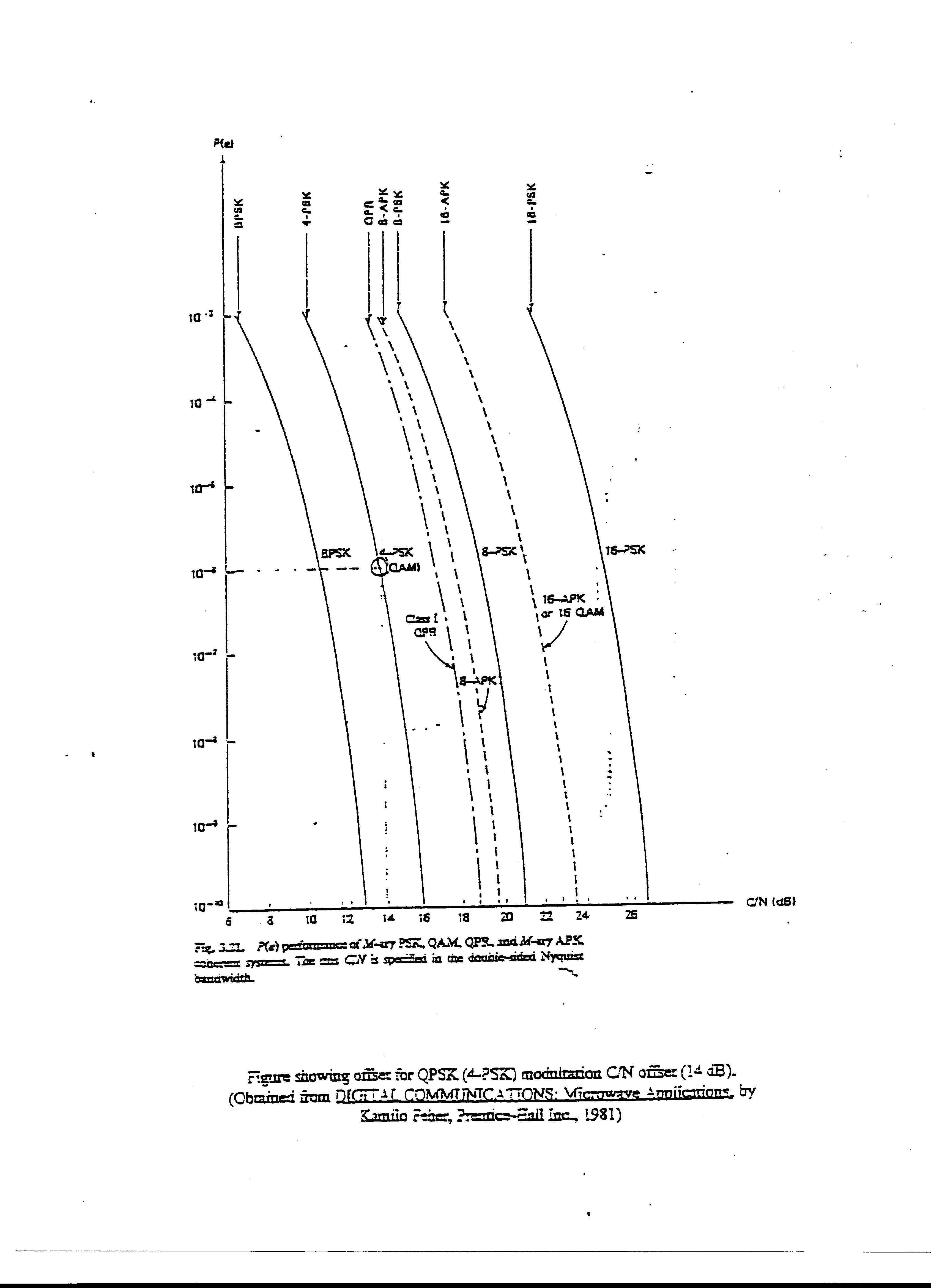
12/08/98 Processing Gain Test for LYNX sc6 (4E) Test Setup: The processing gain was measured using the CW jamming margin method as described in 15.247(e)(2). The specific test diagram is illustrated below. All test equipment and the EUT were allowed to warm up for four hours prior to start of test to minimize drift over time. All test equipment had valid calibration. Calibration of carrier and interferer levels was performed several times during testing with no observed changes. The measurements were performed on the frequency channel centered at 5735 MHz, over a range of + 7 MHz. The measurements made across the center + 6 MHz should be used for calculation of Gp since that bandwidth represents the receiver passband. For the carrier signal, a level approximately 40 dB above threshold was chosen so that thermal noise would not effect the processing gain measurements. The measured threshold of the receive radio was -91 dBm at BER = 1 x 10 -6 , the signal level of the transmit radio was –52.7 dBm measured at the input of the receive radio. The measured signal level of this same signal at the output of the Power Combiner and attenuator was –32.7 dBm (Ps), used for calculating C/I and Gp. For the jammer signal, 0 dBm at the generator corresponds to – 38.5 dBm (Pj) at the combiner output. This figure is also used for calculating C/I and Gp. Test Equipment: Signal GeneratorHewlett Packard 83731A Power MeterHP435B/8484A BER Test SetFireberd 6000 Explanation of Results: The following notations are used on the spreadsheet data: Pg: Power at Generator in dBm (as indicated by generator display). Pj: Power of interferer: Pg –51.65 dBm at power meter test port (calculated in spreadsheet) Ps: Power of carrier at power meter test port. (initial calibration) J/S: Jammer to Signal ratio, Pj-Ps (dB) (calculated in spreadsheet) Gp: Processing Gain: (S/N)o + J/S + Lsys where: Lsys = 2 dB (S/N)o = 13.5 dB for QPSK and BER = 10 -6 (see curve provided) therefore:Gp = 13.5 + 2 + J/S = 15.5 + J/S (calculated in spreadsheet) Only 6 measurements inside the 12 MHz passband of the receiver give Gp results that did not meet the minimum required value of 10 dB. Since 241 steps make up this passband, the 6 measurement points that did not meet specification fall well within the allowed elimination of the worst 20% measurements (see spreadsheet and plotted results). Processing Gain Test Equipment Setup Tx 26 dB Signal Generator Pg Power Meter HP 83731A HP 435B/8484A Set for Rx signal level above threshold 20 dB Rx 9.8 dB FireBERd 6000 Ps, Pj Pwr Cmb. (-3.7 dB) 25 dB
Test Report
1 Processing Gain Data for Lynx 4E1 Radio (31850) Gp (dB) 0 5 10 15 20 25 30 5728 5730 5732 5734 5736 5738 5740 5742 Freq MHz Processing Gain meas #f MHz Gp dBPj dBm Ps dBmJ/S dB 2 1572850.65-16.5-51.6535.15 2 5728.0545.95-21.2-51.6530.45 3 5728.142.15-25-51.6526.65 4 5728.1539.85-27.3-51.6524.35 5 5728.238.55-28.6-51.6523.05 6 5728.2538.65-28.5-51.6523.15 7 5728.337.85-29.3-51.6522.35 8 5728.3536.45-30.7-51.6520.95 9 5728.434.45-32.7-51.6518.95 10 5728.4531.95-35.2-51.6516.45 11 5728.529.35-37.8-51.6513.85 12 5728.5526.65-40.5-51.6511.15 13 5728.624.45-42.7-51.658.95 14 5728.6523.25-43.9-51.657.75 15 5728.722.55-44.6-51.657.05 16 5728.7522.55-44.6-51.657.05 17 5728.822.15-45-51.656.65 18 5728.8521.65-45.5-51.656.15 19 5728.920.95-46.2-51.655.45 20 5728.9520.05-47.1-51.654.55 21572918.95-48.2-51.653.45 22 5729.0517.85-49.3-51.652.35 23 5729.117.05-50.1-51.651.55 24 5729.1516.65-50.5-51.651.15 25 5729.216.35-50.8-51.650.85 26 5729.2516.15-51-51.650.65 27 5729.315.95-51.2-51.650.45 28 5729.3515.85-51.3-51.650.35 29 5729.415.55-51.6-51.650.05 30 5729.4515.15-52-51.65-0.35 31 5729.514.55-52.6-51.65-0.95 32 5729.5514.15-53-51.65-1.35 33 5729.613.85-53.3-51.65-1.65 34 5729.6513.75-53.4-51.65-1.75 35 5729.713.45-53.7-51.65-2.05 36 5729.7513.35-53.8-51.65-2.15 37 5729.813.35-53.8-51.65-2.15 38 5729.8513.35-53.8-51.65-2.15 39 5729.913.35-53.8-51.65-2.15 40 5729.9513.15-54-51.65-2.35 41573012.95-54.2-51.65-2.55 42 5730.0513.05-54.1-51.65-2.45 43 5730.113.15-54-51.65-2.35 44 5730.1513.05-54.1-51.65-2.45 meas #f MHz Gp dBPj dBm Ps dBmJ/S dB 3 45 5730.212.95-54.2-51.65-2.55 46 5730.2513.05-54.1-51.65-2.45 47 5730.313.15-54-51.65-2.35 48 5730.3513.15-54-51.65-2.35 49 5730.413.05-54.1-51.65-2.45 50 5730.4512.85-54.3-51.65-2.65 51 5730.512.85-54.3-51.65-2.65 52 5730.5512.85-54.3-51.65-2.65 53 5730.612.75-54.4-51.65-2.75 54 5730.6512.55-54.6-51.65-2.95 55 5730.712.35-54.8-51.65-3.15 56 5730.7512.45-54.7-51.65-3.05 57 5730.812.45-54.7-51.65-3.05 58 5730.8512.35-54.8-51.65-3.15 59 5730.912.25-54.9-51.65-3.25 60 5730.9512.35-54.8-51.65-3.15 61573112.45-54.7-51.65-3.05 62 5731.0512.45-54.7-51.65-3.05 63 5731.112.35-54.8-51.65-3.15 64 5731.1512.25-54.9-51.65-3.25 65 5731.212.35-54.8-51.65-3.15 66 5731.2512.55-54.6-51.65-2.95 67 5731.312.55-54.6-51.65-2.95 68 5731.3512.45-54.7-51.65-3.05 69 5731.412.35-54.8-51.65-3.15 70 5731.4512.45-54.7-51.65-3.05 71 5731.512.55-54.6-51.65-2.95 72 5731.5512.45-54.7-51.65-3.05 73 5731.612.25-54.9-51.65-3.25 74 5731.6512.25-54.9-51.65-3.25 75 5731.712.35-54.8-51.65-3.15 76 5731.7512.35-54.8-51.65-3.15 77 5731.812.25-54.9-51.65-3.25 78 5731.8512.05-55.1-51.65-3.45 79 5731.912.15-55-51.65-3.35 80 5731.9512.25-54.9-51.65-3.25 81573212.15-55-51.65-3.35 82 5732.0512.05-55.1-51.65-3.45 83 5732.112.05-55.1-51.65-3.45 84 5732.1512.05-55.1-51.65-3.45 85 5732.212.15-55-51.65-3.35 86 5732.2512.05-55.1-51.65-3.45 87 5732.311.95-55.2-51.65-3.55 88 5732.3511.85-55.3-51.65-3.65 89 5732.411.95-55.2-51.65-3.55 90 5732.4511.95-55.2-51.65-3.55 meas #f MHz Gp dBPj dBm Ps dBmJ/S dB 4 91 5732.511.85-55.3-51.65-3.65 92 5732.5511.75-55.4-51.65-3.75 93 5732.611.85-55.3-51.65-3.65 94 5732.6511.95-55.2-51.65-3.55 95 5732.711.95-55.2-51.65-3.55 96 5732.7511.85-55.3-51.65-3.65 97 5732.811.75-55.4-51.65-3.75 98 5732.8511.85-55.3-51.65-3.65 99 5732.911.85-55.3-51.65-3.65 100 5732.9511.65-55.5-51.65-3.85 101573311.45-55.7-51.65-4.05 102 5733.0511.35-55.8-51.65-4.15 103 5733.111.45-55.7-51.65-4.05 104 5733.1511.45-55.7-51.65-4.05 105 5733.211.25-55.9-51.65-4.25 106 5733.2511.25-55.9-51.65-4.25 107 5733.311.35-55.8-51.65-4.15 108 5733.3511.45-55.7-51.65-4.05 109 5733.411.45-55.7-51.65-4.05 110 5733.4511.35-55.8-51.65-4.15 111 5733.511.25-55.9-51.65-4.25 112 5733.5511.35-55.8-51.65-4.15 113 5733.611.45-55.7-51.65-4.05 114 5733.6511.35-55.8-51.65-4.15 115 5733.711.25-55.9-51.65-4.25 116 5733.7511.25-55.9-51.65-4.25 117 5733.811.45-55.7-51.65-4.05 118 5733.8511.45-55.7-51.65-4.05 119 5733.911.35-55.8-51.65-4.15 120 5733.9511.25-55.9-51.65-4.25 121573411.35-55.8-51.65-4.15 122 5734.0511.45-55.7-51.65-4.05 123 5734.111.35-55.8-51.65-4.15 124 5734.1511.15-56-51.65-4.35 125 5734.211.05-56.1-51.65-4.45 126 5734.2511.15-56-51.65-4.35 127 5734.311.15-56-51.65-4.35 128 5734.3511.05-56.1-51.65-4.45 129 5734.410.95-56.2-51.65-4.55 130 5734.4510.95-56.2-51.65-4.55 131 5734.511.05-56.1-51.65-4.45 132 5734.5510.95-56.2-51.65-4.55 133 5734.610.75-56.4-51.65-4.75 134 5734.6510.65-56.5-51.65-4.85 135 5734.710.55-56.6-51.65-4.95 136 5734.7510.55-56.6-51.65-4.95 meas #f MHz Gp dBPj dBm Ps dBmJ/S dB 5 137 5734.810.35-56.8-51.65-5.15 138 5734.8510.05-57.1-51.65-5.45 139 5734.99.85-57.3-51.65-5.65 140 5734.959.95-57.2-51.65-5.55 14157359.6-57.55-51.65-5.9 142 5735.059.85-57.3-51.65-5.65 143 5735.19.75-57.4-51.65-5.75 144 5735.159.95-57.2-51.65-5.55 145 5735.210.15-57-51.65-5.35 146 5735.2510.35-56.8-51.65-5.15 147 5735.310.35-56.8-51.65-5.15 148 5735.3510.35-56.8-51.65-5.15 149 5735.410.55-56.6-51.65-4.95 150 5735.4510.75-56.4-51.65-4.75 151 5735.510.75-56.4-51.65-4.75 152 5735.610.65-56.5-51.65-4.85 153 5735.6510.65-56.5-51.65-4.85 154 5735.710.75-56.4-51.65-4.75 155 5735.7510.85-56.3-51.65-4.65 156 5735.810.75-56.4-51.65-4.75 157 5735.8510.75-56.4-51.65-4.75 158 5735.910.75-56.4-51.65-4.75 159 5735.9510.95-56.2-51.65-4.55 160573610.95-56.2-51.65-4.55 161 5736.0510.75-56.4-51.65-4.75 162 5736.110.65-56.5-51.65-4.85 163 5736.1510.75-56.4-51.65-4.75 164 5736.210.85-56.3-51.65-4.65 165 5736.2510.75-56.4-51.65-4.75 166 5736.310.65-56.5-51.65-4.85 167 5736.3510.65-56.5-51.65-4.85 168 5736.410.85-56.3-51.65-4.65 169 5736.4510.95-56.2-51.65-4.55 170 5736.510.85-56.3-51.65-4.65 171 5736.5510.85-56.3-51.65-4.65 172 5736.610.85-56.3-51.65-4.65 173 5736.6510.95-56.2-51.65-4.55 174 5736.710.95-56.2-51.65-4.55 175 5736.7510.75-56.4-51.65-4.75 176 5736.810.75-56.4-51.65-4.75 177 5736.8510.75-56.4-51.65-4.75 178 5736.910.85-56.3-51.65-4.65 179 5736.9510.75-56.4-51.65-4.75 180573710.75-56.4-51.65-4.75 181 5737.0510.75-56.4-51.65-4.75 182 5737.110.9…
Text truncated - open the document above for the full version.
Contact Information
Applicant
Ken Lim(Accounting Manager)
Technical Contact
Intertek Testing ServicesDavid Chernomordik
[email protected]650/463-2900
1365 Adams Ct. · Menlo Park, California · United States
Non-Technical Contact
Glenayre Western MultiplexKen Ruppel
[email protected]408/542-5276
Test Firm
Intertek Testing Services NA Inc.John Quigley
Technical Specifications
| # | Rule Parts | Frequency Range | Power Output |
|---|---|---|---|
| 1 | 15C | 5.74 GHz - 5.84 GHz | 269.00 mW |
Other Applications from Proxim Wireless Corporation
HZB-MEGA6
Aug 12, 2026EdgeAX 6GHz Radio Module
Equipment Class
6FC - 15E 6 GHz Fixed Client
HZB-GIGA5
Sep 21, 2023Startum X5 Gigabit 5 GHz Radio
Equipment Class
NII - Unlicensed National Information Infrastructure TX
HZB-NGPAP
Apr 26, 2021NGP LC 2.4 & 5 GHz Radios
Equipment Class
NII - Unlicensed National Information Infrastructure TX
HZB-NGPLC
Mar 04, 2021NGP LC 5 GHz Radio
Equipment Class
DTS - Digital Transmission System
HZB-NGP1058W
Nov 03, 2015802.11 ac PCIe Module
Equipment Class
DTS - Digital Transmission System