I5Q200-100-019 Pin Life Scan Cable
LifeScan Inc
Click to zoom
Application Details
- Equipment Class
- JBP - Part 15 Class B Computing Device Peripheral
- Date of Grant
- Sep 03, 2002
- Application Purpose
- Original Equipment
- Date of Application
- Sep 03, 2002
- Equipment Note
- 9 Pin Life Scan Cable
- Company
- LifeScan Inc
- Country
- United States
Documents & Files
Document Text
Text extracted from the exhibit documents filed with the FCC. Open a document above to read the original.
External Photos
TÜV RHEINLAND Product Safety GmbH Am Grauen Stein D-51105 Köln Photo Documentation LifeScan 9 Pin Interface 200-100-01 of HCL Peripehrals (A unit of HCL Infosystems Ltd.) 299, Arcot Road Vadapalani Chennai – 600 026 INDIA This documentation consists of 5 pages include this cover page. TÜV Rheinland Approved __________________________ 2 LifeScan 9 pin Int erface Cable 3 4 5
ID Label/Location Info
LIFESCAN LIFESCAN FONT:ARIAL, HT:1.5MM FONT:ARIAL, HT:1.5MM FONT:ARIAL, HT:2.2MM INTERFACE CABLE 200-100-01 FONT:ARIAL, HT:1.3MM FONT:ARIAL, HT:2.2MM FCC ID I5Q200-100-01 INTERFACE CABLE 200-100-01 All dimensions are in mm INSERT-1 FCC ID:I5Q200-100-01 All dimensions are in mm INSERT-2 LIFESCAN LIFESCAN
Internal Photos
TÜV RHEINLAND Product Safety GmbH Am Grauen Stein D-51105 Köln Photo Documentation LifeScan 9 Pin Interface 200-100-01 of HCL Peripehrals (A unit of HCL Infosystems Ltd.) 299, Arcot Road Vadapalani Chennai – 600 026 INDIA This documentation consists of 5 pages include this cover page. TÜV Rheinland Approved __________________________ 2 LifeScan 9 pin Int erface Cable 3 4 5
Test Report
Attachment 5 FCC ID I5Q200-100-01 Seite 1 von 1 Page 1 of 1 Equipment Under Test (EUT) : 9 pin Life Scan Cable Model No. : 200-100-01 Serial No. : 13 Manufacturer : M/s. HCL Peripherals, Chennai Test Instrumentation: Description Make Model number Serial number Cal. Due date EMI Receiver R&S ESAI-D 825316/004 01/02/03 R&S ESAI-RF 863791/009 01/02/03 EMI Receiver R&S ESI 126 100070 11/10/02 Biconical Antenna AH-system SAS-200/540 423 16/01/03 Log Periodic Antenna Electrometrics LPA 25 1463 06/01/03 EMI Receiver R&S ESCS 30 100063 05/03/03 Line Impedance Stabilization Network (LISN) R&S ESH2-Z5 100034 07/02/03 Applicable Standard: FCC, class B part 15,1998. The test procedures are followed as given in the standard ANSI C63.4 1992 The EMI test receiver (make R&S)(model: ESAI) was used for measuring radiated emission from EUT. The receiver is a sophisticated instrument to specifically carry out EMC measurements. Transducer table settings are available to enter the cable loss & antenna factor in the receiver to get the field strength (dBμV/m) values from the display. So manual calculation is not necessary. For example: E (dBμV/m) = V (dBμV)+AF-----------Eq.1 Where E (dBμV/m) = Field strength V(dBμV) = receiver two terminal voltage AF = Antenna factor Attachment 5 FCC ID I5Q200-100-01 Seite 2 von 2 Page 2 of 2 1. CONDUCTED EMISSION TEST 1.1 EUT Configuration: The 9 pin Life Scan Cable (EUT) was connected to the PC & other subsystems, and other end with 3 pin Pono Plug (to be connected to a meter) was shorted to communicate with the PC. See in Annexure-1 1.2 Test Frequency and limits: Frequency (Mhz) Quasi Peak Limits (dBμV) 0.45-30.0 48 1.3 Test Procedure: The RF conducted emissions from the EUT sent back to the power lines were measured using LISN and EMI receiver. The measurement was done in Peak detection mode. Since the emission level was within the limit in peak mode, measurement was not done in Quasipeak detection mode. 1.4 Test Observations: It was observed that the Conducted Emission from the EUT (9 Pin Life Scan Cable) was within the FCC limits in the test frequency range of 450KHz-30MHz. 1.5 Enclosed Documents: Plot 1 shows conducted emissions from the EUT on Neutral. Plot 2 shows conductd emissions from the EUT on Line Annexure shows the photograph of EUT & Conducted Emission test Setup Attachment 5 FCC ID I5Q200-100-01 Seite 3 von 3 Page 3 of 3 2. RADIATED EMISSION TEST 2.1 EUT Configuration: The 9 Pin Life Scan Cable (EUT) was connected to the PC & other subsystems, and other end with 3 Pin Pono Plug (to be connected to a meter) was shorted to communicate with the PC. 2.2 Test Frequency Range and Limits at 10 meter Distance: Frequency (MHz) Emission Limits (dBμV) 30-88 88-216 216-960 960-1000 29.55 33.05 35.55 43.55 2.3 Test Procedure: (I) The Radiated Emission (RE) from the EUT was first measured in anchoic chamber at 3- meter distance for both horizontal and vertical polarization and antenna height was varied to maximize the emission. The manipulation cables were done to idenfity maximum emissions in the frequency range of 30 Mhz – 1000Mhz to identify any emission from the EUT. The above measurement was done in two steps. Step 1: PC with subsystems in powered condition. Step2: PC with subsystems plus EUT (9 pin Life scan Cable) in powered condition. The frequencies of appreciable emission were identified and recorded (II) The above RE measurement procedure was repreated at OATS (Open Area Test Site) at 10 m distance as required by FCC standard for those tests frequencies with appreciable emission. Measurement was carried out for both horizontal and vertical polarization and antenna height was varied to maximize the emission. The manipulation cables were done to idenfity maximum emissions. The photograph shows the maximum emission condition. 2.4 Test Observations: The Radiated Emission (RE) was within the FCC limit. This was observed in Anchoic chamber with peak detection mode as well as in OATS for the test frequency range of 30-1000Mhz. As the emission from the EUT was below the FCC limit, the measurements plots take in the ancchoic chamber are enclosed for ready reference. 2.7 Enclosed Documents: Plot 3 & 4 shows radiated emission due to ambient (PC & subsystems ON) for the frequency range 30MHz-230Mhz. Plot 5 shows radiated emission due to ambient (PC & Subsystems ON) for the frequency range 230Mhz – 1000Mhz Plot 6&7 shows radiated emissions from the entire setup as shown in Aneexure-1 for the frequency range 30-230Mhz Attachment 5 FCC ID I5Q200-100-01 Seite 4 von 4 Page 4 of 4 Plot 8 &9 shows radiated emissions from the entire setup as shon inAnnexure –1 for the frequency range 230-1000Mhz Power Supply used for testing: Voltage: 120V AC Frequency: 60Hz Desciption of support equipment: Item Make Model Serial no. FCC ID Personal Computer HP VECTRA VL24/50Se IN3MC9735609 HCJVECTRA486-XX Monitor Samsung Samtron, 40Bn HMEJB01171X FCC complied Mouse Logitech M-M34 LZA81902629 DZLZ10365 Keyboard BTC 5207 3872B490 E5XKB5121WTH0110 Attachment 5 FCC ID I5Q200-100-01 Seite 5 von 5 Page 5 of 5 Conducted Emission Qp Band Width: 9KHz Attachment 5 FCC ID I5Q200-100-01 Seite 6 von 6 Page 6 of 6 Attachment 5 FCC ID I5Q200-100-01 Seite 7 von 7 Page 7 of 7 Radiated Emission Qp Band width: 120KHz Attachment 5 FCC ID I5Q200-100-01 Seite 8 von 8 Page 8 of 8 Attachment 5 FCC ID I5Q200-100-01 Seite 9 von 9 Page 9 of 9 Attachment 5 FCC ID I5Q200-100-01 Seite 10 von 10 Page 10 of 10 Attachment 5 FCC ID I5Q200-100-01 Seite 11 von 11 Page 11 of 11 Attachment 5 FCC ID I5Q200-100-01 Seite 12 von 12 Page 12 of 12 Attachment 5 FCC ID I5Q200-100-01 Seite 13 von 13 Page 13 of 13 Attachment 5 FCC ID I5Q200-100-01 Seite 14 von 14 Page 14 of 14 Attachment 5 FCC ID I5Q200-100-01 Seite 15 von 15 Page 15 of 15 Attachment 5 FCC ID I5Q200-100-01 Seite 16 von 16 Page 16 of 16 Attachment 5 FCC ID I5Q200-100-01 Seite 17 von 17 Page 17 of 17
Test Setup Photos
TÜV RHEINLAND Product Safety GmbH Am Grauen Stein D-51105 Köln Photo Documentation LifeScan 9 pin Interface Cable 200-100-01 of HCL Peripehrals (A unit of HCL Infosystems Ltd.) 299, Arcot Road Vadapalani Chennai – 600 026 INDIA This documentation consists of 4 pages include this cover page. TÜV Rheinland Approved __________________________ 2 Condcuted Emission Ra diated Emission (Horizontal Polarisatation) 3 Radiated Emission (Vertical Polarisatation) Radiated Emission (Veritical Polarisatation) 4 Radiated Emision (Horizontal Polarisatation) EUT position
Contact Information
Applicant
Sharbel Noujaim(VP Product Engineering)
Technical Contact
LifeScan IncJohn Diola
408 956 4652
1000 Gibraltar Drive · Milpitas, California · United States
Non-Technical Contact
LifeScan IncJohn Diola
408 956 4652
Test Firm
SAMEERSubbarao B
Technical Specifications
| # | Rule Parts | Frequency Range | Power Output |
|---|---|---|---|
| 1 | 15B | - | - |
Other Applications from LifeScan Inc
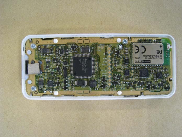
I5QM
Sep 07, 2011Blood Glucose meter with Bluetooth Sync.
Equipment Class
JBP - Part 15 Class B Computing Device Peripheral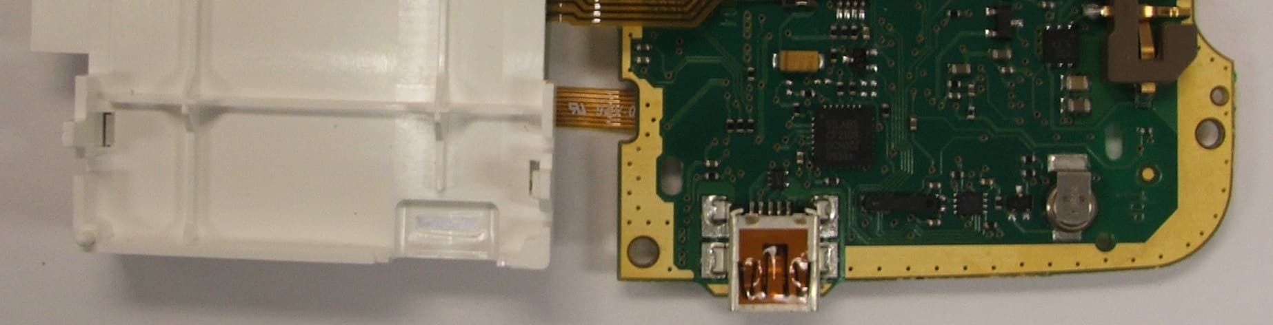
I5QB
Apr 22, 2010OneTouch UltraLink Blood Glucose Meter
Equipment Class
DXT - Part 15 Low Power Transceiver, Rx Verified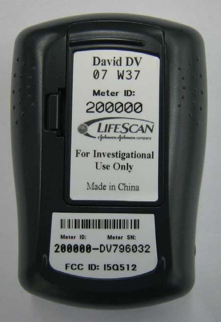
I5Q512
Sep 23, 2007Blood Glucose Monitoring Meter
Equipment Class
DXT - Part 15 Low Power Transceiver, Rx Verified
I5Q200-102-01
Apr 12, 2003Life Scan USB Interface Cable
Equipment Class
JBP - Part 15 Class B Computing Device Peripheral