I88B1202.4 GHz 802.11 PCMCIA Card
ZyXEL Communications Corporation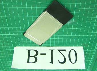
Click to zoom
Application Details
- Equipment Class
- DTS - Digital Transmission System
- Date of Grant
- Jun 04, 2003
- Application Purpose
- Original Equipment
- Date of Application
- Jun 04, 2003
- Equipment Note
- 2.4 GHz 802.11 PCMCIA Card
- Frequency Range
- 2412.00000000 - 2462.00000000
- Country
- Taiwan
Documents & Files
Document Text
Text extracted from the exhibit documents filed with the FCC. Open a document above to read the original.
Users Manual
Compliance Information Product Name: Wireless Lan PC card Model Number: B-120 This above subject device (Wireless Lan PC Card-Model: B-120) complies with Part 15 of the FCC Rules. Operation is subject to the following two conditions : (1) This device may not cause harmful interference, and (2) this device must accept any interference received, including interference that may cause undersired operation. FCC liaison office information in US: Office: ZyXEL Communications Inc., Tel: +1-714-632-0882 Fax: +1-714-632-0858 E-Mail: [email protected]
Users Manual
ZyAIR Wireless LAN Utility User's Guide Version 1.0.0.b5 April 2003 ZyAIR Wireless LAN Utility ii Copyright Copyright Copyright ©2003 by ZyXEL Communications Corporation The contents of this publication may not be reproduced in any part or as a whole, transcribed, stored in a retrieval system, translated into any language, or transmitted in any form or by any means, electronic, mechanical, magnetic, optical, chemical, photocopying, manual, or otherwise, without the prior written permission of ZyXEL Communications Corporation. Published by ZyXEL Communications Corporation. All rights reserved. Disclaimer ZyXEL does not assume any liability arising out of the application or use of any products, or software described herein. Neither does it convey any license under its patent rights nor the patents' rights of others. ZyXEL further reserves the right to make changes in any products described herein without notice. This publication is subject to change without notice. Trademarks Trademarks mentioned in this publication are used for identification purposes only and may be properties of their respective owners. ZyAIR Wireless LAN Utility ZyXEL Limited Warranty iii ZyXEL Limited Warranty ZyXEL warrants to the original end user (purchaser) that this product is free from any defects in materials or workmanship for a period of up to one (1) year from the date of purchase. During the warranty period and upon proof of purchase, should the product have indications of failure due to faulty workmanship and/or materials, ZyXEL will, at its discretion, repair or replace the defective products or components without charge for either parts or labor and to whatever extent it shall deem necessary to restore the product or components to proper operating condition. Any replacement will consist of a new or re-manufactured functionally equivalent product of equal value, and will be solely at the discretion of ZyXEL. This warranty shall not apply if the product is modified, misused, tampered with, damaged by an act of God, or subjected to abnormal working conditions. NOTE Repair or replacement, as provided under this warranty, is the exclusive remedy of the purchaser. This warranty is in lieu of all other warranties, express or implied, including any implied warranty of merchantability or fitness for a particular use or purpose. ZyXEL shall in no event be held liable for indirect or consequential damages of any kind of character to the purchaser. To obtain the services of this warranty, contact ZyXEL's Service Center for your Return Material Authorization (RMA) number. Products must be returned Postage Prepaid. It is recommended that the unit be insured when shipped. Any returned products without proof of purchase or those with an out-dated warranty will be repaired or replaced (at the discretion of ZyXEL) and the customer will be billed for parts and labor. All repaired or replaced products will be shipped by ZyXEL to the corresponding return address, Postage Paid. This warranty gives you specific legal rights, and you may also have other rights that vary from country to country. Online Registration Register online at www.zyxel.com .for free future product updates and information. ZyAIR Wireless LAN Utility iv Information for Canadian Users Information for Canadian Users The Industry Canada label identifies certified equipment. This certification means that the equipment meets certain telecommunications network protective operation and safety requirements. The Industry Canada does not guarantee that the equipment will operate to a user's satisfaction. Before installing this equipment, users should ensure that it is permissible to be connected to the facilities of the local telecommunications company. The equipment must also be installed using an acceptable method of connection. In some cases, the company's inside wiring associated with a single line individual service may be extended by means of a certified connector assembly. The customer should be aware that compliance with the above conditions may not prevent degradation of service in some situations. Repairs to certified equipment should be made by an authorized Canadian maintenance facility designated by the supplier. Any repairs or alterations made by the user to this equipment, or equipment malfunctions, may give the telecommunications company cause to request the user to disconnect the equipment. For their own protection, users should ensure that the electrical ground connections of the power utility, telephone lines, and internal metallic water pipe system, if present, are connected together. This precaution may be particularly important in rural areas. Caution Users should not attempt to make such connections themselves, but should contact the appropriate electrical inspection authority, or electrician, as appropriate. Note This digital apparatus does not exceed the Class A limits for radio noise emissions from digital apparatus set out in the radio interference regulations of Industry. ZyAIR Wireless LAN Utility FCC Statement v Federal Communications Commission (FCC) Interference Statement The Wireless LAN Adapter has been tested to the FCC exposure requirements (Specific Adsorption Rate). This device complies with Part 15 of FCC rules. Operation is subject to the following two conditions: • This device may not cause harmful interference. • This device must accept any interference received, including interference that may cause undesired operations. This equipment has been tested and found to comply with the limits for a Class B digital device pursuant to Part 15 of the FCC Rules. These limits are designed to provide reasonable protection against harmful interference in a commercial environment. This equipment generates, uses, and can radiate radio frequency energy, and if not installed and used in accordance with the instructions, may cause harmful interference to radio communications. If this equipment does cause harmful interference to radio/televis…
Text truncated - open the document above for the full version.
Users Manual
ZyAIR B-120 Wireless LAN PC Card Quick Installation Guide Version 1.0.0.b5 April 2003 2 About Your ZyAIR The ZyAIR is an IEEE 802.11b compliant wireless LAN PC card that fits into any type II PCMCIA slot. Its maximum 11 Mbps data rate, which gives Ethernet equivalent speed, is ideal in the corporate or home environment. Users enjoy the wireless mobility within the coverage area. What’s more, the ZyAIR supports IEEE 802.1x authentication methods for enhanced security that protects the network from intruders. Ad-Hoc Application An ad-hoc network consists of two or more computers communicating with one another through the wireless network. No access points (APs) or existing wired networks are needed. Infrastructure Application When wireless clients wish to access and share resources on the wired network, they should use infrastructure mode. Wireless clients may move or roam from one coverage area to another seamlessly without network interruption. Ad-hoc Network Example 3 Infrastructure Network Example Installation Overview 1. Installation Requirements 2. Hardware Installation 3. Driver Installation 4. ZyAIR Wireless LAN Utility Installation 5. Disable Windows XP Wireless Configuration Tool 6. Accessing the ZyAIR Utility 4 Installation Requirements Before installation, make sure you have the following requirements. • At least 32 MB RAM (64 MB recommended) • A minimum of 20 MB available hard disk space • A CD-ROM drive • A PCMCIA type II slot • Windows 98 SE/ME/2000/XP • Windows 98 SE users may need the Windows 98/98 SE CD Hardware Installation Follow the steps below to install the ZyAIR in your computer. 1. Save your work and close all applications. 2. Locate an available type II PCMCIA slot on the computer. 3. With the pin connector facing the slot and the LED side facing up, slide the ZyAIR into the slot. The LEDs turn on if the ZyAIR is properly inserted. Never bend, force or twist the ZyAIR into the PCMCIA slot. 1 2 5 LED Display LED COLOR STATUS DESCRIPTION Blinking The ZyAIR is receiving or sending data. ACT Blue Off The ZyAIR is not receiving or sending data. On The ZyAIR has a connection to a wireless LAN. Blinking The ZyAIR is connecting to a wireless LAN. LINK Blue Off The ZyAIR is not connected to a wireless LAN or not receiving power. Driver Installation Follow the steps for the appropriate version of Windows to install the ZyAIR driver. After the driver is installed successfully proceed to install the ZyAIR Wireless Utility. 3 6 Windows 98 SE 1. When Windows automatically detects the ZyAIR, click Next. 2. Select Search for the best driver for your device. (Recommended). and click Next. 3. Insert the Installation CD into your CD-ROM drive. Select CD-ROM drive and click Next. 7 4. When prompted, insert the Windows 98 SE CD and click OK. Then specify the location of the Windows 98 SE installation files and click OK. 5. When Add New Hardware Wizard finds the driver file, click Next. 6. Click Finish and restart the computer. Windows Me 1. Windows automatically detects the ZyAIR. Select Specify the location of the driver (Advanced), then click Next. 8 2. Insert the Installation CD into your CD-ROM drive. Select Search for the best drive for your device then select only Removable Media (Floppy, CD-ROM ...) and click Next. 3. When the Add New Hardware Wizard finds the driver, click Next. 4. Click Finish and restart the computer when prompted. Windows 2000 1. When Windows automatically detects the ZyAIR, click Next. 9 2. Insert the Installation CD into your CD-ROM drive. Select Search for a suitable driver for my device (recommended) and click Next. 3. Select CD-ROM drive and click Next. 4. When the Add New Hardware Wizard finds the driver, click Next. 10 5. If a Digital Signature Not Found window displays, click Yes to continue. 6. Click Finish. A Welcome window displays next. Windows XP 1. Windows automatically detects the ZyAIR. Select Install from a list or specific location (Advanced), then click Next. 11 2. Insert the Installation CD into your CD-ROM drive. Select Search for the best drive in these locations then select only Search removable media. (Floppy, CD-ROM ...) and click Next. 3. If the following warning window displays, click Continue Anyway. 4. Click Finish. A Welcome window displays next. 12 ZyAIR Wireless LAN Utility Installation The installation procedures are similar for all support Windows versions. Windows XP screen shots are shown unless otherwise specified. 1. For Windows 98 SE/Me: If the Installation CD is not already in the CD-ROM drive after the computer restarts, a warning screen displays. Insert the Installation CD and click Yes. After you have successfully installed the driver, a Welcome screen displays. Click Next. 4 13 2. Click Next to accept the default file location or click Browse to select an alternate folder. 3. Click Finish to restart the computer and complete the installation process. 14 Disable Windows XP Wireless Configuration Tool Windows XP includes a configuration tool for wireless devices. DO NOT use the Windows XP configuration tool and the ZyAIR Utility at the same time. Always use the ZyXEL Utility to configure the ZyAIR. Follow the steps below to disable the Windows XP configuration tool. 1. Double-click the network icon for wireless connection in the system tray. 2. When a Connect to Wireless Network window displays, click Advanced. 5 15 3. In the Wireless Network Connection Properties window, make sure the Use Windows to configure my wireless network settings check box is not selected. Click OK. 16 Accessing the ZyAIR Utility 1. After the ZyAIR Utility is installed, an icon appears in the system tray. If the ZyAIR Utility icon displays, the ZyAIR is installed properly. 2. Double-click on the ZyAIR Wireless LAN Utility icon in the system tray to open the ZyAIR Wireless LAN Utility program. Refer to the ZyAIR User’s Guide to configure the ZyAIR. Removing the ZyAIR To avoid data lost, DO NOT remove the ZyAIR while data transmission is taki…
Text truncated - open the document above for the full version.
Cover Letter(s)
Aug. 5, 2003 Federal Communication Commission Authorization & Evaluation Laboratories 7435 Oakland Mills Rd. Columbia MD 21046 Attn: Mr. Tim Harrington Subject: FCC ID: I88B120 Applicant: ZyXEL Communications Corporation Correspondence Reference Number: 9079 731 Confirmation Number: TC370314 The distance from bottom of card slot to flat phantom is 14 mm per your review comments. If you have any questions, please feel free to contact me. Best Regards, Elton Chen Assistant Manager Intertek Testing Service Taiwan Ltd. E-mail: [email protected]
External Photos
Photo 1: Outlook photo Photo 2: Outlook photo B-120 B-120
ID Label/Location Info
FCC ID Label Location
Internal Photos
Photo 1: Inner view B-120 B-120 Photo 2: Inner view B-120 B-120 Photo 3: Inner view B-120 B-120 Photo 4: Inner view
RF Exposure Info
0597 ILAC MRA Specific Absorption Rate (SAR) Test Report for ZyXEL on the 802.11b PCMCIA WLAN Card Model Number: B-120 Test Report: EME-030344 Date of Report: March 31, 2003 Date of test: March 27, 2003 Total No of Pages Contained in this Report: 64 Accredited for testing to FCC Part 15 Tested by: Bruce Wu Reviewed by: Elton Chen Review Date: April 3, 2003 All services undertaken are subject to the following general policy: Reports are submitted for exclusive use of the client to whom they are addressed. Their significance is subject to the adequacy and representative character of the samples and to the comprehensiveness of the tests, examinations or surveys made. This report shall not be reproduced except in full, without written consent of Intertek Testing Services, Taiwan Ltd. Intertek Testing Services ETL SEMKO FCC ID. : I88B120 Report No.: EME-030344 Page 2 of 64 STATEMENT OF COMPLIANCE The 802.11b PCMCIA WLAN card sample device, model # B-120 was evaluated in accordance with the requirements for compliance testing defined in FCC OET Bulletin 65, Supplement C (Edition 01-01). Testing was performed at the Intertek Testing Services facility in Hsinchu, Taiwan. For the evaluation, the dosimetric assessment system INDEXSAR SARA2 was used. The phantom employed was the box phantom of 2mm thick in one wall. The total uncertainty for the evaluation of the spatial peak SAR values averaged over a cube of 1g tissue mass had been assessed for this system to be ±27.5%. The device was tested at their maximum output power declared by the ZyXEL In summary, the maximum spatial peak SAR value for the sample device averaged over 1g was found to be: Phantom Position SAR 1g , mW/g 2mm thick box phantom wall Right side of the Laptop touching the phantom 1.301 In conclusion, the tested Sample device was found to be in compliance with the requirements defined in OET Bulletin 65, Supplement C (Edition 01-01) for body configurations. Intertek Testing Services ETL SEMKO FCC ID. : I88B120 Report No.: EME-030344 Page 3 of 64 1.0 JOB DESCRIPTION 1.1 Client Information The B-120 has been tested at the request of: Company: ZyXEL Communications Corporation No. 6, Innovation Rd II, Science-Based Industrial Park, Hsin-Chu, Taiwan 1.2 Equipment under test (EUT) Product Descriptions: Equipment 802.11b PCMCIA WLAN Card Trade Name ZyXEL Model No: B-120 FCC ID I88B120 S/N No. Not Labeled Category Portable RF Exposure Uncontrolled Environment Frequency Band 2412 – 2462 MHz System DSSS EUT Antenna Description Type Ceramic antenna Configuration Fixed Dimensions 53.8 x 114.6mm Gain 2.5 dBi Location PCMCIA Note: The serial model ZyAIR B-120, is identical to the basic model, B-120, for marketing purpose only. Use of Product : Wireless Data Communication Manufacturer: ZyXEL Production is planned: [X] Yes, [ ] No EUT receive date: Mar. 14, 2003 EUT received condition: Good operating condition prototype. Test start date: March 27, 2003 Test end date: March 27, 2003 Intertek Testing Services ETL SEMKO FCC ID. : I88B120 Report No.: EME-030344 Page 4 of 64 1.3 Test plan reference FCC Rule: Part 2.1093, FCC's OET Bulletin 65, Supplement C (Edition 01-01) 1.4 System test configuration 1.4.1 Test setup and procedure: Plug the EUT into Notebook via extend card, and turn on the power, then run the test program “ZDConfig” under Window OS. The EUT was transmitted continuously during the test. 1.4.2 System block diagram & Support equipment Support Equipment Item # Equipment Model No. S/N 1 Acer Laptop Computer 500 N/A EUT Installed inside laptop with a PCMCIA slot (lower) Intertek Testing Services ETL SEMKO FCC ID. : I88B120 Report No.: EME-030344 Page 5 of 64 1.4.3 Test Position Box Phantom Display Antenna Keyboard Figure 1: Bottom side of Laptop facing phantom Keyboard Antenna Figure 2: EUT perpendicular to phantom with distance 0 mm Display Intertek Testing Services ETL SEMKO FCC ID. : I88B120 Report No.: EME-030344 Page 6 of 64 1.4.4 Test Condition During tests the worst-case data (max RF coupling) was determined with following conditions: Usage Operates with a portable computer Distance between antenna axis at the joint and the liquid surface: Laptop is touching the Phantom in all positions Simulating human Head/ Body/Hand Body EUT Battery Device is powered from host computer through battery Channel Frequency MHz Before SAR Test (mW) After SAR Test (mW) Low Channel - 1 2412 17.12 17.12 Mid Channel - 6 2437 17.38 17.38 Conducted output Power High Channel- 11 2462 16.99 16.99 The spatial peak SAR values were assessed for lowest, middle and highest operating channels, defined by the manufacturer. The conducted output power was measured before and after the test using an average power meter. 1.5 Modifications required for compliance Intertek Testing Services implemented no modifications. 1.6 Additions, deviations and exclusions from standards The phantom employed was the box phantom of 2 mm thick in vertical wall. Intertek Testing Services ETL SEMKO FCC ID. : I88B120 Report No.: EME-030344 Page 7 of 64 2.0 SAR EVALUATION 2.1 SAR Limits The following FCC limits for SAR apply to devices operate in General Population/Uncontrolled Exposure environment: EXPOSURE (General Population/Uncontrolled Exposure environment) SAR (W/kg) Average over the whole body 0.08 Spatial Peak (1g) 1.60 Spatial Peak for hands, wrists, feet and ankles (10g) 4.00 Intertek Testing Services ETL SEMKO FCC ID. : I88B120 Report No.: EME-030344 Page 8 of 64 2.2 Configuration Photographs SAR Measurement Test Setup Test System Intertek Testing Services ETL SEMKO FCC ID. : I88B120 Report No.: EME-030344 Page 9 of 64 SAR Measurement Test Setup Bottom side of Laptop facing phantom touching Intertek Testing Services ETL SEMKO FCC ID. : I88B120 Report No.: EME-030344 Page 10 of 64 SAR Measurement Test Setup Bottom side of Laptop facing phantom touching Intertek Testing Services ETL SEMKO FCC ID. : I88B120 Report No.: EME-030344 Page 11 of 64 SAR Measurement Test Setup EUT perpendic…
Text truncated - open the document above for the full version.
RF Exposure Info
1. Normal scan setting by default for evaluation test: X depth extent 34mm 10 steps Y lateral extent 32mm 5 steps Z lateral extent 32mm 5 steps As above scanned cube 2. System validation scan setting: X lateral extent 32mm 5 steps Y lateral extent 32mm 5 steps Z depth extent 34mm 7 steps As above scanned cube Normal scan setting (default) System validation scan setting
Test Report
Intertek Testing Services ETL SEMKO FCC ID. : I88B120 Report No.: EME-030138 Page 1 of 23 EMC TEST REPORT Report No. : EME-030138 Model No. : B-120 Issued Date : Feb. 13, 2003 Applicant : ZyXEL Communications Corporation No. 6, Innovation Rd II, Science-Based Industrial Park, Hsin-Chu, Taiwan Test By : Intertek Testing Services Taiwan Ltd. No. 11, Ko-Tze-Nan Chia-Tung Li, Shiang-Shan District, Hsinchu, Taiwan This test report consists of 23 pages in total. It may be duplicated completely for legal use with the allowance of the applicant. It shall not be reproduced except in full, without the written approval of ITS Laboratory. The test result in this report only applies to the tested sample. Kaysi Chen Project Engineer Reviewed By Elton Chen Intertek Testing Services ETL SEMKO FCC ID. : I88B120 Report No.: EME-030138 Page 2 of 23 Table of Contents Summary of Tests.........................................................................................................3 1. General information..................................................................................................4 1.1 Identification of the EUT....................................................................................4 1.2 Additional information about the EUT................................................................4 1.3 Antenna description............................................................................................5 1.4 Peripherals equipment.........................................................................................5 2. Test specifications.....................................................................................................6 2.1 Test standard.......................................................................................................6 2.2 Operation mode...................................................................................................6 2.3 Test equipment....................................................................................................7 3. Minimum 6dB Bandwidth test..................................................................................8 3.1 Operating environment........................................................................................8 3.2 Test setup & procedure........................................................................................8 3.3 Measured data of Minimum 6dB Bandwidth test results......................................8 4. Maximum Output Power test....................................................................................9 4.1 Operating environment........................................................................................9 4.2 Test setup & procedure........................................................................................9 4.3 Measured data of Maximum Output Power test results........................................9 5. Radiated Emission test............................................................................................10 5.1 Operating environment......................................................................................10 5.2 Test setup & procedure......................................................................................10 5.3 Emission limits.................................................................................................11 5.4 Radiated spurious emission test data.................................................................12 5.4.1 Measurement results: frequencies equal to or less than 1 GHz........................12 5.4.2 Measurement results: frequency above 1GHz.................................................15 6. Power Spectrum Density test..................................................................................18 6.1 Operating environment......................................................................................18 6.2 Test setup & procedure......................................................................................18 6.3 Measured data of Power Spectrum Density test results......................................18 7. Emission on the band edge §FCC 15.247(C)...........................................................19 8. Power Line Conducted Emission test §FCC 15.207................................................20 8.1 Operating environment......................................................................................20 8.2 Test setup & procedure......................................................................................20 8.3 Power Line Conducted Emission test data.........................................................21 Intertek Testing Services ETL SEMKO FCC ID. : I88B120 Report No.: EME-030138 Page 3 of 23 Summary of Tests Wireless Lan PC Card-Model: B-120 FCC ID: I88B120 Test Reference Results Minimum 6dB Bandwidth test 15.247(a)(2) Complies Maximum Output Power test 15.247(b) Complies Radiated Spurious Emission test 15.205, 15.209 Complies Power Spectrum Density test 15.247(d) Complies Power Line Conducted Emission test 15.207 Complies Intertek Testing Services ETL SEMKO FCC ID. : I88B120 Report No.: EME-030138 Page 4 of 23 1. General information 1.1 Identification of the EUT Applicant : ZyXEL Communications Corp. Product : Wireless Lan PC Card Model No. : B-120 FCC ID. : I88B120 Frequency Range : 2400MHz to 2483.5MHz Channel Number : 11 Frequency of Each Channel : 2412MHz, 2417MHz, 2422MHz, 2427MHz, 2432MHz, 2437MHz, 2442MHz, 2447MHz, 2452MHz, 2457MHz, 2462MHz Type of Modulation : CCK (11Mps, 5.5Mbps), DQPSK (2Mbps), DBPSK (1Mbps) Power Supply : 5Vdc from Notebook Power Cord : N/A Sample Received : Jan. 29, 2003 Test Date(s) : Jan. 29, 2003 to Feb. 11, 2003 A FCC DoC report has been generated for the client. 1.2 Additional information about the EUT The ZyAIR is an IEEE 802.11b compliant wireless PCMCIA card that fits into any type II PCMCIA slot. Its maximum 11 Mbps data rate, which gives Ethernet equivalent speed, is …
Text truncated - open the document above for the full version.
Test Setup Photos
Photo 1: Conducted Test Set-up (front) Photo 2: Conducted Test Set-up (rear)
Test Setup Photos
Photo 1: Spurious Test Set-up (front) Photo 2: Spurious Test Set-up (rear)
Contact Information
Applicant
Emma Bao(Section Manager)
Technical Contact
Intertek Testing Services Taiwan Ltd.Elton Chen
[email protected](+886)-3-519-1411
No. 11, Ko-Tze-Nan Chia-Tung Li · Hsinchu · Taiwan
Non-Technical Contact
Intertek Testing Services Taiwan Ltd.Elton Chen
[email protected](+886)-3-519-1411
Test Firm
Intertek Testing Services Taiwan Ltd.Alpha Liu
Technical Specifications
| # | Rule Parts | Frequency Range | Power Output |
|---|---|---|---|
| 1 | 15C | 2.41 GHz - 2.46 GHz | 55.00 mW |
Other Applications from ZyXEL Communications Corporation
I88EE6601-00
Jul 18, 2024Tri-Band Wireless BE19000 10G Ethernet VoIP Gateway with SFP+ / Tri-Band Wireless BE19000 10G Ethernet VoIP Gateway / Tri-Band Wireless BE19000 10G Ethernet Gateway with SFP+ / Tri-Band Wireless BE19000 10G Ethernet Gateway
Equipment Class
6ID - 15E 6 GHz Low Power Indoor Access Point
I8803935
Oct 17, 2023802.11be (WiFi 7) Triple-Radio Unified Pro Access Point
Equipment Class
DTS - Digital Transmission System
I8803973
Aug 01, 2023802.11ax (WiFi 6) Dual-Radio Wall-Plate Unified Access Point
Equipment Class
NII - Unlicensed National Information Infrastructure TX
I88WX5610-B0
Apr 25, 2023AX7800 WiFi 6E Tri-Band Gigabit Wireless Extender
Equipment Class
DTS - Digital Transmission System
I88EX7710-B0
Apr 16, 2023AX11000 WiFi 6E 10G Ethernet Gateway
Equipment Class
NII - Unlicensed National Information Infrastructure TX