I88FR1000ZWireless N FTTH Router
ZyXEL Communications Corporation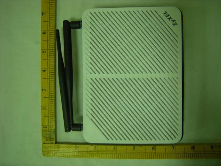
Click to zoom
Application Details
- Equipment Class
- DTS - Digital Transmission System
- Date of Grant
- Jul 13, 2010
- Application Purpose
- Original Equipment
- Date of Application
- Jul 12, 2010
- Equipment Note
- Wireless N FTTH Router
- Frequency Range
- 2422.00000000 - 2452.00000000
- Country
- Taiwan
Documents & Files
Document Text
Text extracted from the exhibit documents filed with the FCC. Open a document above to read the original.
Users Manual
3 Introduction FR1000Z is a router that provides high-speed Internet access, a built-in switch, a firewall and high-speed wireless networking capability. It allows you to enjoy high-bandwidth applications, such as video streaming, on- line gaming and peer-to-peer (P2P). You can also set up a secure wireless network connection using the WPS button. Before You Begin Make sure you have the following things before you set up your FR1000Z. • Internet access - account information provided by your ISP, such as user name, password, and so on. • Internet Explorer 6.0, Firefox 3.6, Safari: 4.0.5, Opera: 10.51 or Chrome 4.1.249.1064 as well as later versions of all these browsers, with JavaScript enabled. 4 Hardware Connections This section shows you how to set up your FR1000Z. 1. WAN: Use an Ethernet cable to connect this port to an Ethernet jack with Internet access. 2. ETHERNET: Use an Ethernet cable to connect a computer to this port for initial configuration and/or Internet access. 3. Use the power adaptor provided with your FR1000Z to connect an appropriate power source to this socket. As of writing, the USB port is reserved for future use. 5 Checking the LEDs (Lights) Look at the LEDs (lights) on the top panel of the FR1000Z. • The POWER light blinks during start-up and is green once the FR1000Z is ready. • The WAN light is green if the Internet connection exists and blinks when transmitting data. • The INTERNET light is green when Internet access is available. • The ETHERNET light turns on if the ETHERNET port is properly connected. The light blinks when the FR1000Z is sending or receiving data through the ETHERNET port. • The WIFI light turns on when the wireless network is enabled. If none of the LEDs (lights) are on, check your connections. Make sure that you have the power adaptor connected to the FR1000Z and plugged in to an appropriate power source. Make sure the power source is turned on. Turn the FR1000Z off, wait for a few seconds and turn it back on. If the LEDs are still off, contact your local vendor. As of writing, the USB LED is reserved for future use. 6 Testing Internet Connection After you have connected the hardware and turned on the FR1000Z, open a web browser on your computer and go to any web site (for example, www.zyxel.com) to test your Internet connection. If you are prompted for a user name and password, enter the account information as given by your Internet service provider (ISP). If the INTERNET light is off but the WAN light is on, go to the Initial Configuration section to configure your Internet access settings. Initial Configuration 1. Open your browser and enter http://192.168.0.1 (the FR1000Z's default IP address) as the address. 2. The main screen displays. 7 If the main screen does not display, make sure your computer is set to get an IP address automatically from a DHCP server. Click Quick Setup from the main screen. Follow the instructions in the screen and enter the Internet access information exactly as given to you by your ISP and click Apply. 8 3. If your ISP didn’t provide you a username and password, click the Advanced IP Configuration button. Configure your FR1000Z for Internet access according to instructions provided by your ISP. Make sure you enter the correct information. When your Internet connection is set up correctly, the WAN and INTERNET lights should be green. Set Up a WPS Connection Press the WPS button on the FR1000Z’s front panel for more than 5 seconds to turn the WPS function on. Follow these steps to add a WPS-enabled device to the wireless network using the WPS button. Place the devices you want to connect near one another. Press the WPS button on the FR1000Z. The WPS light blinks. Press the WPS button on a compatible device within 2 minutes of pressing the button on the FR1000Z. The WPS light on the FR1000Z shines steadily when connected. 1 2 3 9 Wall-mounting Take the following steps to hang your FR1000Z on a wall. 1. Select a position free of obstructions on a sturdy wall. 2. Drill two holes for the screws, exactly 110 mm apart. 3. Be careful to avoid damaging pipes or cables located inside the wall when drilling holes for the screws. 4. Do not insert the screws all the way into the wall. Leave a small gap of about 0.5 cm between the heads of the screws and the wall. 5. Make sure the screws are snugly fastened to the wall. They need to hold the weight of the FR1000Z with the connection cables. 6. Align the holes on the back of the FR1000Z with the screws on the wall. Hang the FR1000Z on the screws. 10 Customer Information Statement The information informing the user of his and the telephone company's rights and obligations is outlined on the following pages. This information will be included in the final version of the manual. 1. This equipment complies with Part 68 of the FCC rules and the requirements adopted by the ACTA. On bottom of this equipment is a label that contains, among other information, a product identifier of QWEST FR1000Z. If requested, this number must be provided to the telephone company. 2. If this equipment DL causes harm to the telephone network, the telephone company will notify you in advance that temporary discontinuance of service may be required. But if advance notice isn’t practical, the telephone company will notify the customer as soon as possible. Also you will be advised of your right to file a complaint with the FCC if you believe it is necessary. 3. The telephone company may make changes in its facilities, equipment, operations or procedures that could affect the operation of the equipment. If this happens, the telephone company will provide advance notice in order for you to make necessary modification to maintain uninterrupted service. 4. If you experience trouble with this equipment, you disconnect it from the network until the problem has been corrected or until you are sure that the equipment is not malfunctioning. 5. Please follow instructions for repairing if any (e.g. battery repla…
Text truncated - open the document above for the full version.
Cover Letter(s)
Attestation for FCC Declaration of Conformity FCC ID: I88FR1000Z Date: Jul 06, 2010 Please be notified that we, the undersigned, Cerpass technology Coporation declares that the product which bears the above FCC ID is a;so compliant with the FCC requirements for DOC. The test report number supporting the DOC is SEFD1006040. Testing in regards to this report was done by Cerpass technology Coporation, located at No. 7-2, Moshihkeng, Fongtian Village, Shihding Township, Taipei County, Taiwan, R.O.C., which has been accredited in accordance to all of the requirements of 47 CFR 2.948(d) and(e)of the FCC rules and KDB349827. Sincerely, Anson Chou / Manager Tel: +886-2-26558100#5301 Fax: +886-2-26558200 Email: [email protected]
External Photos
Wireless N FTTH Router (Model name: FR1000Z) Exterior Photographs: 1) 2) 3) 4) 5) 6) 7) 8) 9) 10)
ID Label/Location Info
Wireless N FTTH Router (Model name: FR1000Z) FCC ID Position: FCC ID
Internal Photos
Wireless N FTTH Router (Model name: FR1000Z) Inside photo: 1) 2) 3) 4) 5) 6) 7) 8) 9)
RF Exposure Info
Page: 1 of 3 RF Exposure Evaluation Declaration Product: Wireless N FTTH Router Test Item: RF Exposure Evaluation Declaration 1. RF Exposure Evaluation 1.1. Limits According to FCC 1.1310: The criteria listed in the following table shall be used to evaluate the environment impact of human exposure to radio frequency (RF) radiation as specified in 1.1307(b) LIMITS FOR MAXIMUM PERMISSIBLE EXPOSURE (MPE) Frequency Range (MHz) Electric Field Strength (V/m) Magnetic Field Strength (A/m) Power Density (mW/cm2) Average Time (Minutes) (A) Limits for Occupational/ Control Exposures 300-1500 -- -- F/300 6 1500-100,000 -- -- 5 6 (B) Limits for General Population/ Uncontrolled Exposures 300-1500 -- -- F/1500 6 1500-100,000 -- -- 1 30 F= Frequency in MHz Friis Formula Friis transmission formula: Pd = (Pout*G)/(4*pi*r2) Where Pd = power density in mW/cm2 Pout = output power to antenna in mW G = gain of antenna in linear scale Pi = 3.1416 R = distance between observation point and center of the radiator in cm Pd id the limit of MPE, 1 mW/cm2 . If we know the maximum gain of the antenna and the total power input to the antenna, through the calculation, we will know the distance r where the MPE limit is reached. Page: 2 of 4 1.2. Test Procedure Software provided by client enabled the EUT to transmit and receive data at lowest, middle and highest channel individually. The temperature and related humidity: 18°Cand 78% RH. 1.3. EUT Operation condition Software provided by client enabled the EUT to transmit and receive data at lowest, middle and highest channel individually. 1.4. Test Result of RF Exposure Evaluation Antenna Gain: Ant0: antenna type: Dipole antenna antenna antenna gain: 5.7dBi Ant1: antenna type: Dipole antenna antenna antenna gain: 5.7dBi Output Power Into Antenna & RF Exposure Evaluation Distance: 1) 802.11b Test date: Channel Channel Frequency (MHz) Output Power to Antenna (mW) Power Density at R = 20 cm (mW/cm2) 01 2412.00 120.5036 0.0890695 06 2437.00 118.0321 0.0872427 11 2462.00 108.3927 0.0801178 2) 802.11g Test date: Channel Channel Frequency (MHz) Output Power to Antenna (mW) Power Density at R = 20 cm (mW/cm2) 01 2412.00 149.9685 0.1108483 06 2437.00 169.0441 0.1249480 11 2462.00 145.5459 0.1075794 Page: 3 of 4 3) 802.11n(20MHz) (An0) Test date: Channel Channel Frequency (MHz) Output Power to Antenna (mW) Power Density at R = 20 cm (mW/cm2) 01 2412.00 204.6445 0.1512618 06 2437.00 190.1078 0.1405171 11 2462.00 168.6553 0.1246606 4) 802.11n(20MHz) (An1) Test date: Channel Channel Frequency (MHz) Output Power to Antenna (mW) Power Density at R = 20 cm (mW/cm2) 01 2412.00 151.7050 0.1121319 06 2437.00 159.2209 0.1176872 11 2462.00 141.2538 0.1044069 3) 802.11n(20MHz) (An1 and An0) Test date: Channel Channel Frequency (MHz) Output Power to Antenna (mW) Power Density at R = 20 cm (mW/cm2) 01 2412.00 356.4511 0.263469 06 2437.00 349.1403 0.258065 11 2462.00 309.7419 0.228944 5) 802.11n(40MHz) (An0) Test date: Channel Channel Frequency (MHz) Output Power to Antenna (mW) Power Density at R = 20 cm (mW/cm2) 03 2422.00 106.1696 0.0784746 06 2437.00 98.8553 0.0730683 09 2452.00 94.1890 0.0696193 Page: 4 of 4 6) 802.11n(40MHz) (An1) Test date: Channel Channel Frequency (MHz) Output Power to Antenna (mW) Power Density at R = 20 cm (mW/cm2) 03 2422.00 137.0882 0.1013279 06 2437.00 133.0454 0.0983397 09 2452.00 127.0574 0.0939137 7) 802.11n(40MHz) (An1 and An0) Test date: Channel Channel Frequency (MHz) Output Power to Antenna (mW) Power Density at R = 20 cm (mW/cm2) 03 2422.00 243.2204 0.1797749 06 2437.00 231.7395 0.1712889 09 2452.00 221.3095 0.1635796 Note: The power density Pd (4th column) at a distance of 20 cm calculated from the Friis transmission formula is far below the limit of 1 mW/cm2.
Test Report
CERPASS TECHNOLOGY CORP. Report No.: SEFI1006040 Cerpass Technology Corp. Issued Date : Jul 01,2010 Tel:86-512-6917-5888 Fax: 86-512-6917-5666 Page No. : 1 of 156 FCC TEST REPORT According to FCC CFR Title 47 Part 15 Subpart C Applicant : ZyXEL Communications Corp. Address : No. 6, Innovation Road II, Science Park, Hsinchu 300, Taiwan Manufacturer : ZyXEL Communications Corp. Address : 60#-E Minshan Road, Wuxi New District Jiangsu PRC Equipment : Wireless N FTTH Router Model No. : FR1000Z FCC ID : I88FR1000Z The test result refers exclusively to the test presented test model / sample. Without written approval of Cerpass Technology Corp. the test report shall not be reproduced except in full. The test report must not be used by the clients to claim product certification approval by NVLAP or any agency of the Government. CERPASS TECHNOLOGY CORP. Report No.: SEFI1006040 Cerpass Technology Corp. Issued Date : Jul 01,2010 Tel:86-512-6917-5888 Fax: 86-512-6917-5666 Page No. : 2 of 156 Table of Contents 1. Report of Measurements and Examinations.............................................................................................6 2. Test Configuration of Equipment under Test............................................................................................7 2.1. Feature of Equipment under Test .................................................................................................... 7 2.2. Carrier Frequency of Channels ....................................................................................................... 8 2.3. Test Manner ..................................................................................................................................... 9 2.4. Description of Test System .............................................................................................................. 9 2.5. Connection Diagram of Test System ............................................................................................. 10 2.6. General Information of Test ............................................................................................................11 2.7. Measurement Uncertainty ..............................................................................................................11 3. Test of Conducted Emission ....................................................................................................................12 3.1. Test Limit........................................................................................................................................ 12 3.2. Test Procedures............................................................................................................................. 12 3.3. Typical Test Setup.......................................................................................................................... 13 3.4. Measurement Equipment .............................................................................................................. 13 3.5. Test Result and Data ..................................................................................................................... 14 4. Test of Radiated Emission ........................................................................................................................18 4.1. Test Limit........................................................................................................................................ 18 4.2. Test Procedures............................................................................................................................. 18 4.3. Typical Test Setup.......................................................................................................................... 19 4.4. Measurement Equipment .............................................................................................................. 20 4.5. Test Result and Data ..................................................................................................................... 21 5. Occupied Bandwidth .................................................................................................................................93 5.1. Test Limit........................................................................................................................................ 93 5.2. Test Procedures............................................................................................................................. 93 5.3. Test Setup Layout .......................................................................................................................... 93 5.4. Measurement Equipment .............................................................................................................. 93 5.5. Test Result and Data ..................................................................................................................... 94 6. Maximum Peak Output Power ................................................................................................................106 6.1. Test Limit...................................................................................................................................... 106 6.2. Test Procedure ............................................................................................................................ 106 6.3. Test Setup Layout ........................................................................................................................ 107 6.4. Measurement Equipment ............................................................................................................ 107 6.5. Test Result and Data ................................................................................................................... 108 7. Band Edges ...................................................................................................................................…
Text truncated - open the document above for the full version.
Test Setup Photos
Wireless N FTTH Router (Model name: FR1000Z) Test Photograph: Front View of Conducted Emission Test Back View of Conducted Emission Test Front View of Radiated Emission Test Back View of Radiated Emission Test
Contact Information
Applicant
Emma Bao(Section Manager)
Technical Contact
Cerpass Technology CorporationJohn Wang
[email protected]+86-512-69175888
No.66, Tangzhuang Road · JiangSu · China
Non-Technical Contact
Cerpass Technology Corporationmandy liu
[email protected]+86-512-69175888
Test Firm
Cerpass Technology (SuZhou) Co., Ltd.Alex Chiu
Technical Specifications
| # | Rule Parts | Frequency Range | Power Output |
|---|---|---|---|
| 2 | 15C | 2.42 GHz - 2.45 GHz | 243.00 mW |
Other Applications from ZyXEL Communications Corporation
I88EE6601-00
Jul 18, 2024Tri-Band Wireless BE19000 10G Ethernet VoIP Gateway with SFP+ / Tri-Band Wireless BE19000 10G Ethernet VoIP Gateway / Tri-Band Wireless BE19000 10G Ethernet Gateway with SFP+ / Tri-Band Wireless BE19000 10G Ethernet Gateway
Equipment Class
6ID - 15E 6 GHz Low Power Indoor Access Point
I8803935
Oct 17, 2023802.11be (WiFi 7) Triple-Radio Unified Pro Access Point
Equipment Class
DTS - Digital Transmission System
I8803973
Aug 01, 2023802.11ax (WiFi 6) Dual-Radio Wall-Plate Unified Access Point
Equipment Class
NII - Unlicensed National Information Infrastructure TX
I88WX5610-B0
Apr 25, 2023AX7800 WiFi 6E Tri-Band Gigabit Wireless Extender
Equipment Class
DTS - Digital Transmission System
I88EX7710-B0
Apr 16, 2023AX11000 WiFi 6E 10G Ethernet Gateway
Equipment Class
NII - Unlicensed National Information Infrastructure TX