I88G162802.11g Wireless CardBus Card
ZyXEL Communications Corporation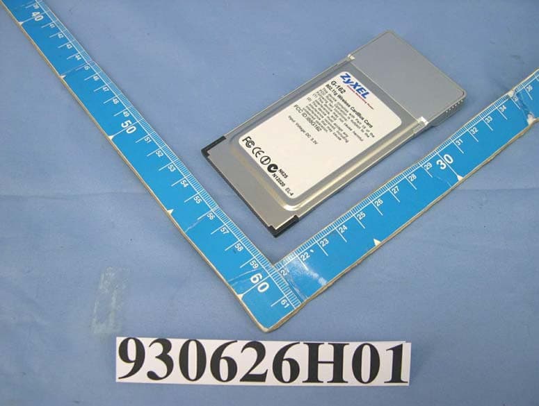
Click to zoom
Application Details
- Equipment Class
- DTS - Digital Transmission System
- Date of Grant
- Aug 31, 2004
- Application Purpose
- Original Equipment
- Date of Application
- Aug 31, 2004
- Equipment Note
- 802.11g Wireless CardBus Card
- Frequency Range
- 2412.00000000 - 2462.00000000
- Country
- Taiwan
Documents & Files
Document Text
Text extracted from the exhibit documents filed with the FCC. Open a document above to read the original.
Users Manual
ZyXEL G-162 802.11g Wireless CardBus Card Quick Start Guide ZyXEL G-162 Quick Start Guide 1 Important Note Federal Communications Commission (FCC) Interference Statement The 802.11g Wireless LAN Adapter has been tested to the FCC exposure requirements (Specific Absorption Rate). The equipment complies with FCC RF radiation exposure limits set forth for an uncontrolled environment, under 47 CFR 2.1093 paragraph (d) (2). This Transmitter must not be co-located or operating in conjunction with any other antenna or transmitter. Refer to the User’s Guide for general FCC statements. Procedure to View a Product’s Certification(s) 1. Go to www.zyxel.com 2. Select your product from the drop-down list box on the ZyXEL home page to go to that product's page. 3. Select the certification you wish to view from this page. About Your ZyXEL G-162 The ZyXEL G-162 is an IEEE 802.11g compliant wireless LAN PC card that fits into any CardBus slot. With the ZyXEL G-162, you can enjoy the wireless mobility within the coverage area. The IEEE 802.11g technology provides greater range and offers transmission rate at up to 54 Mbps. Your ZyXEL G-162 can transmit at the proprietary transmission rate of 125 Mbps if you are connecting to the ZyXEL G- 162 and G-560 (at the time of writing). ZyXEL G-162 Quick Start Guide 2 1. Installation Requirements Before installation, make sure you have a computer with the following: • Pentium II 300MHz or above • A minimum of 6 MB available hard disk space • A minimum of 32 MB RAM • A CD-ROM drive • A CardBus slot • Windows 98 SE/Me/2000/XP • Windows 98 SE users may need the Windows 98 SE CD ) If you install the Funk Odyssey Client software on the computer, uninstall (remove) it. 2. ZyXEL Utility and Hardware Installation The installation procedures are similar for all supported Windows versions. Windows 2000 screen shots are shown unless otherwise specified. ) DO NOT insert the ZyXEL G-162 at this point. 1. Insert the support CD into the CD-ROM drive on your computer. The CD automatically runs. Otherwise, locate and double-click setup.exe. ZyXEL G-162 Quick Start Guide 3 2. Select your language and click OK. 3. Click Install Utility to start installation. 4. A welcome screen displays. Click Next. 5. Click Next to accept the default file location or click Browse to select an alternate folder. 6. Click Finish to restart the computer. ZyXEL G-162 Quick Start Guide 4 7. Locate an available CardBus slot on the computer. 8. With the pin connectors facing the slot and the LED side facing up, slide the ZyXEL G-162 into the slot. The LEDs turn on if the ZyXEL G-162 is properly inserted. ) Never bend, force or twist the ZyXEL G-162 into the slot. After you install the ZyXEL Utility and insert the ZyXEL G-162, an icon appears in the system tray. ) If the ZyXEL Utility icon displays, the ZyXEL G-162 is installed properly. Refer to the User’s Guide to configure the ZyXEL G-162. LED Display The following table describes the LEDs on the ZyXEL G-162. LINK PWR ZyXEL G-162 Quick Start Guide 5 LED COLOR STATUS DESCRIPTION On The ZyXEL G-162 is receiving power. PWR Green Off The ZyXEL G-162 is not receiving power. Blinking The ZyXEL G-162 is receiving or sending data. LINK Green Off The ZyXEL G-162 is not receiving or sending data. Troubleshooting PROBLEM CORRECTIVE ACTION Make sure the ZyXEL G-162 is inserted into the computer CardBus slot properly and then restart your computer. Check the LEDs on the ZyXEL G-162. Perform a hardware scan by clicking Start, Settings, Control Panel and double-clicking Add/Remove Hardware. (Steps may vary depending on the version of Windows). Follow the on-screen instructions to search for the ZyXEL G- 162 and install the driver. Check for possible hardware conflicts. In Windows, click Start, Settings, Control Panel, System, Hardware and then click Device Manager. Verify the status of the ZyXEL G-162 under Network Adapter. (Steps may vary depending on the version of Windows). Windows does not auto-detect the ZyXEL G-162. Install the ZyXEL G-162 in another computer. If the error persists, you may have a hardware problem. In this case, you should contact your local vendor. Federal Communication Commission Interference Statement This equipment has been tested and found to comply with the limits for a Class B digital device, pursuant to Part 15 of the FCC Rules. These limits are designed to provide reasonable protection against harmful interference in a residential installation. This equipment generates, uses and can radiate radio frequency energy and, if not installed and used in accordance with the instructions, may cause harmful interference to radio communications. However, there is no guarantee that interference will not occur in a particular installation. If this equipment does cause harmful interference to radio or television reception, which can be determined by turning the equipment off and on, the user is encouraged to try to correct the interference by one of the following measures: - Reorient or relocate the receiving antenna. - Increase the separation between the equipment and receiver. - Connect the equipment into an outlet on a circuit different from that to which the receiver is connected. - Consult the dealer or an experienced radio/TV technician for help. This device complies with Part 15 of the FCC Rules. Operation is subject to the following two conditions: (1) This device may not cause harmful interference, and (2) this device must accept any interference received, including interference that may cause undesired operation. FCC Caution: Any changes or modifications not expressly approved by the party responsible for compliance could void the user's authority to operate this equipment. IMPORTANT NOTE: FCC Radiation Exposure Statement: This equipment complies with FCC radiation exposure limits set forth for an uncontrolled environment. End users must follow the specific operating instructions for satisfying RF exposure compliance. This transmitter must no…
Text truncated - open the document above for the full version.
External Photos
Page 1 CONSTRUCTION PHOTOS OF EUT Page 2
ID Label/Location Info
(Fig. 1) FCC ID: I88G162 FCC LABEL LOCATION The label will be permanently affixed at a conspicuous location on the device. Label
ID Label/Location Info
40.0 mm 6 4 . 0 m m 4-R2.5
Internal Photos
Page 3 Page 4 Page 5 Page 6
Operational Description
FCC ID: 188G162 Report No. 930626H02 Operational Description This device is a 802.11g Wireless CardBus Card, the maximum data rate could be up to 54Mbps which OFDM technique will be applied. If the signal to noise radio is too poor which could not support 54Mbps, the 11Mbps data rate with CCK technique will be applied. The transmitter of the EUT (802.11g Wireless CardBus Card) is powered from host equipment. The antenna type used in this Printed antenna with HRS MS-156 connector. The other instruction, please have a look at the users manual.
RF Exposure Info
FCC ID:I88G162 Report No.: SA930626H011Issued: 09 Aug., 2004 SAR TEST REPORT REPORT NO.: SA930626H01 MODEL NO.: G-162 RECEIVED: 26 June, 2004 TESTED: 06 Aug., 2004 APPLICANT: ZyXEL Communications Corporation ADDRESS: No. 6, Innovation Rd II, Science-Based Industrial Park, Hsinchu, Taiwan, R.O.C. ISSUED BY: Advance Data Technology Corporation LAB LOCATION: No. 19, Hwa Ya 2nd rd., Kueishan,Taoyuan, Taiwan, R.O.C. This test report consists of 31 pages in total except Appendix. It may be duplicated completely for legal use with the approval of the applicant. It should not be reproduced except in full, without the written approval of our laboratory. The client should not use it to claim product endorsement by CNLA or any government agencies. The test results in the report only apply to the tested sample. 0528 ILAC MRA FCC ID:I88G162 Report No.: SA930626H012Issued: 09 Aug., 2004 Table of Contents 1.CERTIFICATION...............................................................................................................3 2.GENERAL INFORMATION................................................................................................4 2.1GENERAL DESCRIPTION OF EUT...................................................................................4 2.2GENERAL DESCRIPTION OF APPLIED STANDARDS.......................................................5 2.3GENERAL INOFRMATION OF THE SAR SYSTEM........................................................ ....5 2.4GENERAL DESCRIPTION OF THE SPATIAL PEAK SAR EVALUATION..............................9 3.DESCRIPTION OF TEST MODES AND CONFIGURATIONS.............................................13 4.DESCRIPTION OF SUPPORT UNITS..............................................................................14 5.TEST RESULTS..............................................................................................................15 5.1TEST PROCEDURES.....................................................................................................15 5.2MEASURED SAR RESULT..............................................................................................16 5.3SAR LIMITS....................................................................................................................18 5.4RECIPES FOR TISSUE SIMULATING LIQUIDS...............................................................18 5.5TEST EQUIPMENT FOR TISSUE PROPERTY.................................................................20 6.SYSTEM VALIDATION....................................................................................................21 6.1TEST EQUIPMENT.........................................................................................................21 6.2TEST PROCEDURE.......................................................................................................21 6.3VALIDATION RESULT.....................................................................................................23 6.4SYSTEM VALIDATION UNCERTAINTIES.........................................................................24 7.MEASUREMENT SAR PROCEDURE UNCERTAINTIES...................................................25 7.1PROBE CALIBRATION UNCERTAINTY...........................................................................25 7.2ISOTROPY UNCERTA INTY.............................................................................................25 7.3BOUNDARY EFFECT UNCERTAINTY.............................................................................26 7.4PROBE LINEARITY UNCERTAINTY................................................................................26 7.5READOUT ELECTRONICS UNCERTAINTY.....................................................................26 7.6RESPONSE TIME UNCERTAINTY..................................................................................27 7.7INTEGRATION TIME UNCERTAINTY..............................................................................28 7.8PROBE POSITIONER MECHANICAL TOLERANCE.........................................................28 7.9PROBE POSITIONING....................................................................................................29 7.10PHANTOM UNCERTA INTY.............................................................................................29 7.11DASY4 UNCERTAINTY BUDGET....................................................................................30 8.INFORMATION ON THE TESTING LABORATORIES........................................................31 APPENDIX A: TEST CONFIGURATIONS AND TEST DATA APPENDIX B: ADT SAR MEASUREMENT SYSTEM APPENDIX C: PHOTOGRAPHS OF SYSTEM VALIDATION APPENDIX D: SYSTEM CERTIFICATE & CALIBRATION FCC ID:I88G162 Report No.: SA930626H013Issued: 09 Aug., 2004 1. CERTIFICATION PRODUCT : 802.11g Wireless CardBus Card MODEL NO. : G-162 BRAND NAME : ZyXEL APPLICANT : ZyXEL Communications Corporation TESTED : 06 Aug., 2004 TEST ITEM : ENGINEERING SAMPLE STANDARDS : FCC Part 2(Section 2.1093), FCC OET Bulletin 65, Supplement C (01-01), RSS-102 The above equipment has been tested by Advance Data Technology Corporation, and found compliance with the requirement of the above standards. The test record, data evaluation & Equipment Under Test (EUT) configurations represented herein are true and accurate accounts of the measurements of the sample’ s EMC characteristics under the conditions specified in this report. PREPARED BY:, DATE:09 Aug., 2004 ( Windy Chou ) TECHNICAL ACCEPTANCE : , DATE:09 Aug., 2004 Responsible for RF ( Ansen Lei ) APPROVED BY:, DATE:09 Aug., 2004 ( Cody Chang, Supervisor ) FCC ID:I88G162 Report No.: SA930626H014Issued: 09 Aug., 2004 2. GENERAL INFORMATION 2.1 GENERAL DESCRIPTION OF EUT PRODUCT 802.11g Wireless CardBus Card MODEL NO. G-162 POWER SUPPLY 3.3Vdc powered by host equipment CLASSIFICATION Portable device, production unit MODULATION TYPE BPSK, QPSK, CCK, 16QAM, 64QAM RADIO TECHNOLOGY DSSS, OFDM TRANSFER RATE 54/48/36/24/18/12/11/9/6/5.5/2/1 Mbps FREQUENCY RANGE 241…
Text truncated - open the document above for the full version.
RF Exposure Info
D3:DAE
RF Exposure Info
D4:2450MHZ SYSTEM VALIDATION DIPOLE
Test Report
FCC ID: I88G162 Report No.: RF930626H01 1 Issued: Jul. 12, 2004 FCC TEST REPORT REPORT NO.:RF930626H01 MODEL NO.:G-162 RECEIVED:Jun. 26, 2004 TESTED:Jul. 02, 2004 APPLICANT: ZyXEL Communications Corporation ADDRESS: No. 6, Innovation Rd II, Science-Based Industrial ISSUED BY: Advance Data Technology Corporation LAB LOCATION: No. 19, Hwa Ya 2nd rd., Kueishan, Taoyuan, Taiwan, R.O.C. This test report consists of 70 pages in total. It may be duplicated completely for legal use with the approval of the applicant. It should not be reproduced except in full, without the written approval of our laboratory. The client should not use it to claim product endorsement by any government agencies. The test results in the report only apply to the tested sample. FCC ID: I88G162 Report No.: RF930626H01 2 Issued: Jul. 12, 2004 Table of Contents 1 CERTIFICATION ........................................................................................... 4 2 SUMMARY OF TEST RESULTS................................................................... 5 3 GENERAL INFORMATION ........................................................................... 6 3.1 GENERAL DESCRIPTION OF EUT.............................................................. 6 3.2 DESCRIPTION OF TEST MODES................................................................ 7 3.3 GENERAL DESCRIPTION OF APPLIED STANDARDS ............................... 7 3.4 DESCRIPTION OF SUPPORT UNITS.......................................................... 8 3.5 CONFIGURATION OF SYSTEM UNDER TEST ........................................... 9 4 TEST TYPES AND RESULTS..................................................................... 10 4.1 CONDUCTED EMISSION MEASUREMENT .............................................. 10 4.1.1 LIMITS OF CONDUCTED EMISSION MEASUREMENT............................ 10 4.1.2 TEST INSTRUMENTS ................................................................................ 10 4.1.3 TEST PROCEDURES..................................................................................11 4.1.4 DEVIATION FROM TEST STANDARD ........................................................11 4.1.5 TEST SETUP .............................................................................................. 12 4.1.6 EUT OPERATING CONDITIONS................................................................ 13 4.1.7 TEST RESULTS.......................................................................................... 14 4.2 RADIATED EMISSION MEASUREMENT ................................................... 20 4.2.1 LIMITS OF RADIATED EMISSION MEASUREMENT................................. 20 4.2.2 TEST INSTRUMENTS ................................................................................ 21 4.2.3 TEST PROCEDURES................................................................................. 22 4.2.4 DEVIATION FROM TEST STANDARD ....................................................... 22 4.2.5 TEST SETUP .............................................................................................. 23 4.2.6 EUT OPERATING CONDITIONS................................................................ 23 4.2.7 TEST RESULTS.......................................................................................... 24 4.2.8 TEST RESULTS (A) .................................................................................... 26 4.2.9 TEST RESULTS (B) .................................................................................... 29 4.3 6DB BANDWIDTH MEASUREMENT.......................................................... 32 4.3.1 LIMITS OF 6DB BANDWIDTH MEASUREMENT ....................................... 32 4.3.2 TEST INSTRUMENTS ................................................................................ 32 4.3.3 TEST PROCEDURE ................................................................................... 33 4.3.4 DEVIATION FROM TEST STANDARD ....................................................... 33 4.3.5 TEST SETUP .............................................................................................. 33 4.3.6 EUT OPERATING CONDITIONS................................................................ 33 4.3.7 TEST RESULTS (A) .................................................................................... 34 FCC ID: I88G162 Report No.: RF930626H01 3 Issued: Jul. 12, 2004 4.3.8 TEST RESULTS (B) .................................................................................... 38 4.4 MAXIMUM PEAK OUTPUT POWER .......................................................... 42 4.4.1 LIMITS OF MAXIMUM PEAK OUTPUT POWER MEASUREMENT ........... 42 4.4.2 TEST INSTRUMENTS ................................................................................ 42 4.4.3 TEST PROCEDURES................................................................................. 43 4.4.4 DEVIATION FROM TEST STANDARD ....................................................... 43 4.4.5 TEST SETUP .............................................................................................. 43 4.4.6 EUT OPERATING CONDITIONS................................................................ 43 4.4.7 TEST RESULTS (A) .................................................................................... 44 4.4.8 TEST RESULTS (B) .................................................................................... 45 4.5 POWER SPECTRAL DENSITY MEASUREMENT...................................... 46 4.5.1 LIMITS OF POWER SPECTRAL DENSITY MEASUREMENT ................... 46 4.5.2 TEST INSTRUMENTS ................................................................................ 46 4.5.3 TEST PROCEDURE ................................................................................... 47 4.5.4 DEVIATION FROM TEST STANDARD ....................................................... 47 4.5.5 TEST SETUP .............................................................................................. 47 4.5.6 EUT OPERATING CONDIT…
Text truncated - open the document above for the full version.
Test Report
FCC ID: I88G162 Report No.: RF930626H01 41 Issued: Jul. 12, 2004 CH11 FCC ID: I88G162 Report No.: RF930626H01 42 Issued: Jul. 12, 2004 4.4 MAXIMUM PEAK OUTPUT POWER 4.4.1 LIMITS OF MAXIMUM PEAK OUTPUT POWER MEASUREMENT The Maximum Peak Output Power Measurement is 30dBm. 4.4.2 TEST INSTRUMENTS Description & Manufacturer Model No. Serial No. Calibrated Until R&S SPECTRUM ANALYZER FSP40 100036 Nov. 27, 2004 AGILENT SIGNAL GENERATOR E8257C MY43320668 Jan. 01, 2005 TEKTRONIX OSCILLOSCOPE TDS 220 B027241 Jun. 30, 2005 NARDA DETECTOR 4503A FSCM99899 NA NOTE: The calibration interval of the above test instruments is 12 months and the calibrations are traceable to NML/ROC and NIST/USA. FCC ID: I88G162 Report No.: RF930626H01 43 Issued: Jul. 12, 2004 4.4.3 TEST PROCEDURES 1. A detector was used on the output port of the EUT. An oscilloscope was used to read the response of the detector. 2. Replaced the EUT by the signal generator. The center frequency of the S.G. was adjusted to the center frequency of the measured channel. 3. Adjusted the power to have the same reading on oscilloscope. Record the power level. 4.4.4 DEVIATION FROM TEST STANDARD No deviation 4.4.5 TEST SETUP 4.4.6 EUT OPERATING CONDITIONS Same as Item 4.3.6 Detector EUT or S.G. OSCILLOSCOPE FCC ID: I88G162 Report No.: RF930626H01 44 Issued: Jul. 12, 2004 4.4.7 TEST RESULTS (A) EUT 802.11g Wireless CardBus Card MODEL G-162 INPUT POWER (SYSTEM) 120 Vac, 60 Hz ENVIRONMENTAL CONDITIONS 25 deg. C, 60% RH, 991 hPa TESTED BY Tony Chen CHANNEL CHANNEL FREQUENCY (MHz) PEAK POWER OUTPUT (dBm) PEAK POWER LIMIT (dBm) PASS/ FAI L 1 2412 16.50 30 PASS 6 2437 16.50 30 PASS 11 2462 16.50 30 PASS FCC ID: I88G162 Report No.: RF930626H01 45 Issued: Jul. 12, 2004 4.4.8 TEST RESULTS (B) EUT 802.11g Wireless CardBus Card MODEL G-162 INPUT POWER (SYSTEM) 120 Vac, 60 Hz ENVIRONMENTAL CONDITIONS 25 deg. C, 60% RH, 991 hPa TESTED BY Tony Chen CHANNEL CHANNEL FREQUENCY (MHz) PEAK POWER OUTPUT (dBm) PEAK POWER LIMIT (dBm) PASS/ FAI L 1 2412 16.40 30 PASS 6 2437 16.40 30 PASS 11 2462 16.40 30 PASS FCC ID: I88G162 Report No.: RF930626H01 46 Issued: Jul. 12, 2004 4.5 POWER SPECTRAL DENSITY MEASUREMENT 4.5.1 LIMITS OF POWER SPECTRAL DENSITY MEASUREMENT The Maximum of Power Spectral Density Measurement is 8dBm. 4.5.2 TEST INSTRUMENTS Description & Manufacturer Model No. Serial No. Calibrated Until R&S SPECTRUM ANALYZER FSP40 100036 Nov. 27, 2004 NOTE: 1.The measurement uncertainty is less than +/- 2.6dB, which is calculated as per the NAMAS document NIS81. 2.The calibration interval of the above test instruments is 12 months and the calibrations are traceable to NML/ROC and NIST/USA. FCC ID: I88G162 Report No.: RF930626H01 47 Issued: Jul. 12, 2004 4.5.3 TEST PROCEDURE The transmitter output was connected to the spectrum analyzer through an attenuator, the bandwidth of the fundamental frequency was measured with the spectrum analyzer using 3 kHz RBW and 30 kHz VBW, set sweep time=span/3kHz. The power spectral density was measured and recorded. The sweep time is allowed to be longer than span/3KHz for a full response of the mixer in the spectrum analyzer. 4.5.4 DEVIATION FROM TEST STANDARD No deviation 4.5.5 TEST SETUP 4.5.6 EUT OPERATING CONDITIONS Same as 4.3.6 EUT SPECTRUM ANALYZER FCC ID: I88G162 Report No.: RF930626H01 48 Issued: Jul. 12, 2004 4.5.7 TEST RESULTS (A) EUT 802.11g Wireless CardBus Card MODEL G-162 INPUT POWER (SYSTEM) 120 Vac, 60 Hz ENVIRONMENTAL CONDITIONS 25 deg. C, 60% RH, 991 hPa TESTED BY Tony Chen CHANNEL NUMBER CHANNEL FREQUENCY (MHz ) RF POWER LEVEL IN 3KHz BW (dBm) MAXIMUM LIMIT (dBm) PASS/FAIL 1 2412 -10.67 8 PASS 6 2437 -10.03 8 PASS 11 2462 -10.38 8 PASS FCC ID: I88G162 Report No.: RF930626H01 49 Issued: Jul. 12, 2004 CH1 FCC ID: I88G162 Report No.: RF930626H01 50 Issued: Jul. 12, 2004 CH6 FCC ID: I88G162 Report No.: RF930626H01 51 Issued: Jul. 12, 2004 CH11 FCC ID: I88G162 Report No.: RF930626H01 52 Issued: Jul. 12, 2004 4.5.8 TEST RESULTS (B) EUT 802.11g Wireless CardBus Card MODEL G-162 INPUT POWER (SYSTEM) 120 Vac, 60 Hz ENVIRONMENTAL CONDITIONS 25 deg. C, 60% RH, 991 hPa TESTED BY Tony Chen CHANNEL NUMBER CHANNEL FREQUENCY (MHz ) RF POWER LEVEL IN 3KHz BW (dBm) MAXIMUM LIMIT (dBm) PASS/FAIL 1 2412 -12.23 8 PASS 6 2437 -12.11 8 PASS 11 2462 -11.90 8 PASS FCC ID: I88G162 Report No.: RF930626H01 53 Issued: Jul. 12, 2004 CH1 FCC ID: I88G162 Report No.: RF930626H01 54 Issued: Jul. 12, 2004 CH6 FCC ID: I88G162 Report No.: RF930626H01 55 Issued: Jul. 12, 2004 CH11 FCC ID: I88G162 Report No.: RF930626H01 56 Issued: Jul. 12, 2004 4.6 BAND EDGES MEASUREMENT 4.6.1 LIMITS OF BAND EDGES MEASUREMENT Below –20dB of the highest emission level of operating band (in 100kHz Resolution Bandwidth). 4.6.2 TEST INSTRUMENTS Description & Manufacturer Model No. Serial No. Calibrated Until R&S SPECTRUM ANALYZER FSP40 100036 Nov. 27, 2004 NOTE: 1.The measurement uncertainty is less than +/- 2.6dB, which is calculated as per the NAMAS document NIS81. 2.The calibration interval of the above test instruments is 12 months and the calibrations are traceable to NML/ROC and NIST/USA. 4.6.3 TEST PROCEDURE The transmitter output was connected to the spectrum analyzer via a low lose cable. Set both RBW and VBW of spectrum analyzer to 1MHz and 10Hz with suitable frequency span including 100MHz bandwidth from band edge. The band edges was measured and recorded. 4.6.4 DEVIATION FROM TEST STANDARD No deviation 4.6.5 EUT OPERATING CONDITION Same as Item 4.3.6 FCC ID: I88G162 Report No.: RF930626H01 57 Issued: Jul. 12, 2004 4.6.6 TEST RESULTS (A) The spectrum plots are attached on the following 4 pages. D2 line indicates the highest level, D1 line indicates the 20dB offset below D2. It shows compliance with the requirement in part 15.247(C). NOTE: The band edge emission plot on the following 1~2 pages show 58.91dB delta between carrier maximum power and local maximum emission in restrict band (2.3900GHz). The emission of carrier strength list in the test result of channel …
Text truncated - open the document above for the full version.
Test Setup Photos
FCC ID: I88G162 Report No.: RF930626H01 68 Issued: Jul. 12, 2004 5 PHOTOGRAPHS OF THE TEST CONFIGURATION CONDUCTED EMISSION TEST FCC ID: I88G162 Report No.: RF930626H01 69 Issued: Jul. 12, 2004 RADIATED EMISSION TEST
Contact Information
Applicant
Emma Bao(Section Manager)
Technical Contact
Advance Data Technology CorporationEric Lin
[email protected]+886-3-593-5343
81-1 Luliaoken, 9th Lin, Wulung Tsuen Chiunglin · Hsinchu · Taiwan
Test Firm
Bureau Veritas CPS (H.K.) Ltd. Taoyuan BranchRichard Chen
Technical Specifications
| # | Rule Parts | Frequency Range | Power Output |
|---|---|---|---|
| 1 | 15C | 2.41 GHz - 2.46 GHz | 45.00 mW |
Other Applications from ZyXEL Communications Corporation
I88EE6601-00
Jul 18, 2024Tri-Band Wireless BE19000 10G Ethernet VoIP Gateway with SFP+ / Tri-Band Wireless BE19000 10G Ethernet VoIP Gateway / Tri-Band Wireless BE19000 10G Ethernet Gateway with SFP+ / Tri-Band Wireless BE19000 10G Ethernet Gateway
Equipment Class
6ID - 15E 6 GHz Low Power Indoor Access Point
I8803935
Oct 17, 2023802.11be (WiFi 7) Triple-Radio Unified Pro Access Point
Equipment Class
DTS - Digital Transmission System
I8803973
Aug 01, 2023802.11ax (WiFi 6) Dual-Radio Wall-Plate Unified Access Point
Equipment Class
NII - Unlicensed National Information Infrastructure TX
I88WX5610-B0
Apr 25, 2023AX7800 WiFi 6E Tri-Band Gigabit Wireless Extender
Equipment Class
DTS - Digital Transmission System
I88EX7710-B0
Apr 16, 2023AX11000 WiFi 6E 10G Ethernet Gateway
Equipment Class
NII - Unlicensed National Information Infrastructure TX