I88G220V2WLAN USB Adapter
ZyXEL Communications Corporation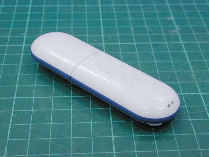
Click to zoom
Application Details
- Equipment Class
- DTS - Digital Transmission System
- Date of Grant
- Mar 16, 2006
- Application Purpose
- Original Equipment
- Date of Application
- Mar 16, 2006
- Equipment Note
- WLAN USB Adapter
- Frequency Range
- 2412.00000000 - 2462.00000000
- Country
- Taiwan
Documents & Files
Document Text
Text extracted from the exhibit documents filed with the FCC. Open a document above to read the original.
Users Manual
ZyXEL G-220 v2 802.11g WLAN USB Adapter User’s Guide Version 1.00 Edition 1 3/2006 ZyXEL G-220 v2 User’s Guide Copyright3 Copyright Copyright © 2006 by ZyXEL Communications Corporation. The contents of this publication may not be reproduced in any part or as a whole, transcribed, stored in a retrieval system, translated into any language, or transmitted in any form or by any means, electronic, mechanical, magnetic, optical, chemical, photocopying, manual, or otherwise, without the prior written permission of ZyXEL Communications Corporation. Published by ZyXEL Communications Corporation. All rights reserved. Disclaimer ZyXEL does not assume any liability arising out of the application or use of any products, or software described herein. Neither does it convey any license under its patent rights nor the patent rights of others. ZyXEL further reserves the right to make changes in any products described herein without notice. This publication is subject to change without notice. Trademarks ZyNOS (ZyXEL Network Operating System) is a registered trademark of ZyXEL Communications, Inc. Other trademarks mentioned in this publication are used for identification purposes only and may be properties of their respective owners. ZyXEL G-220 v2 User’s Guide 4Federal Communications Commission (FCC) Interference Statement Federal Communications Commission (FCC) Interference Statement The device complies with Part 15 of FCC rules. Operation is subject to the following two conditions: • This device may not cause harmful interference. • This device must accept any interference received, including interference that may cause undesired operations. This equipment has been tested and found to comply with the limits for a Class B digital device pursuant to Part 15 of the FCC Rules. These limits are designed to provide reasonable protection against harmful interference in a commercial environment. This equipment generates, uses, and can radiate radio frequency energy, and if not installed and used in accordance with the instructions, may cause harmful interference to radio communications. If this equipment does cause harmful interference to radio/television reception, which can be determined by turning the equipment off and on, the user is encouraged to try to correct the interference by one or more of the following measures: 1Reorient or relocate the receiving antenna. 2Increase the separation between the equipment and the receiver. 3Connect the equipment into an outlet on a circuit different from that to which the receiver is connected. 4Consult the dealer or an experienced radio/TV technician for help. Notice 1 Changes or modifications not expressly approved by the party responsible for compliance could void the user's authority to operate the equipment. This product has been designed for the WLAN 2.4 GHz network throughout the EC region and Switzerland, with restrictions in France. Caution 1The equipment complies with FCC RF radiation exposure limits set forth for an uncontrolled environment, under 47 CFR 2.1093 paragraph (d)(2). 2This Transmitter must not be co-located or operating in conjunction with any other antenna or transmitter. ZyXEL G-220 v2 User’s Guide Federal Communications Commission (FCC) Interference Statement5 Certifications 1Go to www.zyxel.com. 2Select your product from the drop-down list box on the ZyXEL home page to go to that product's page. 3Select the certification you wish to view from this page. 注意 ! 依據 低功率電波輻射性電機管理辦法 第十二條 經型式認證合格之低功率射頻電機,非經許可,公司、商號或使用 者均不得擅自變更頻率、加大功率或變更原設計之特性及功能。 第十四條 低功率射頻電機之使用不得影響飛航安全及干擾合法通信;經發現 有干擾現象時,應立即停用,並改善至無干擾時方得繼續使用。 前項合法通信,指依電信規定作業之無線電信。低功率射頻電機須忍 受合法通信或工業、科學及醫療用電波輻射性電機設備之干擾。 ZyXEL G-220 v2 User’s Guide 6ZyXEL Limited Warranty ZyXEL Limited Warranty ZyXEL warrants to the original end user (purchaser) that this product is free from any defects in materials or workmanship for a period of up to two (2) years from the date of purchase. During the warranty period, and upon proof of purchase, should the product have indications of failure due to faulty workmanship and/or materials, ZyXEL will, at its discretion, repair or replace the defective products or components without charge for either parts or labor, and to whatever extent it shall deem necessary to restore the product or components to proper operating condition. Any replacement will consist of a new or re-manufactured functionally equivalent product of equal or higher value, and will be solely at the discretion of ZyXEL. This warranty shall not apply if the product has been modified, misused, tampered with, damaged by an act of God, or subjected to abnormal working conditions. Note Repair or replacement, as provided under this warranty, is the exclusive remedy of the purchaser. This warranty is in lieu of all other warranties, express or implied, including any implied warranty of merchantability or fitness for a particular use or purpose. ZyXEL shall in no event be held liable for indirect or consequential damages of any kind to the purchaser. To obtain the services of this warranty, contact ZyXEL's Service Center for your Return Material Authorization number (RMA). Products must be returned Postage Prepaid. It is recommended that the unit be insured when shipped. Any returned products without proof of purchase or those with an out-dated warranty will be repaired or replaced (at the discretion of ZyXEL) and the customer will be billed for parts and labor. All repaired or replaced products will be shipped by ZyXEL to the corresponding return address, Postage Paid. This warranty gives you specific legal rights, and you may also have other rights that vary from country to country. Online Registration Register your product online to receive e-mail notices of firmware upgrades and information at www.zyxel.com for global products, or at www.us.zyxel.com for North American products. ZyXEL G-220 v2 User’s Guide Customer Support7 Customer Support Please have the following information ready when you contact custom…
Text truncated - open the document above for the full version.
Cover Letter(s)
Confidentility Letter (Permanent) Attention: Application Examiner Re: Request for confidentiality Applicant: ZyXEL Communications Corporation FCC ID: I88G220V2 To whom it may concern, Permanent Confidentiality Request is hereby submitted by ZyXEL Communications Corporation to withhold permanently from public review certain portions of the application for equipment certification for the referenced FCC identifiers. This request for confidentiality is made pursuant to 47 CFR 0.457(d) of the FCC Rules. In particular, the following sections of the application are to be kept permanently confidential: • Schematics • Detailed Block diagrams • Detailed Operational/Functional Description Rationale for request for confidentiality: ZyXEL Communications Corporation has invested considerable time and materials in research and development to produce the referenced product. [Permanent confidentiality: Disclosure of the permanently confidential portions of this application to competitors would not only give them significant competitive advantages in developing similar products, but would also disclose successful implementation of unpublished, leading edge technology developed by us.] If you have questions or need further information, please contact the undersigned. Sincerely, Mar. 3, 2006 Yi Wang ZyXEL Communications Corporation
Cover Letter(s)
American Telecommunications Certification Body Inc. 6731 Whittier Ave, McLean, VA 22101 March 14, 2006 RE: ZyXEL Communications Corporation FCC ID: I88G220V2 After a review of the submitted information for FCC, I have a few comments on the above referenced Application. FCC Review 1) Section 15.15(b) prohibits adjustments of any control by the user that will cause operation of a device in violation of the regulations. Accordingly, any proposal to allow the end user to choose extended channels on frequencies outside of an allowable frequency band in the USA is not acceptable. For example, a WLAN device operating according to Section 15.247 on channels 1- 11 between 2.4 - 2.483.5 GHz must not have any user controls or software to allow the device to operate on channels 12 and 13 which are outside of the allowed USA band. For instance, the user should not be able to select alternative countries which would allow different channel plans outside of the allowed USA band. Please explain how this device is compliant to this requirement. 2) Page 66 of the users manual mentions a maximum output power of 19.1 dBm +/- 3 dB for 802.11 b, 22.94 dBm +/- 3 dbm for 802.11g. Please note that the FCC expects worse case power to be measured during testing. Please note that +3 dB above power measured seems excessive. If worse case power was not used then this will require retetsting. Please review. 3) 802.11g power spectral density tests does not appear to match data provided in plots. Please review. 4) Please explain if all SAR data was taken in a 24 hour period. 2 test dates appear, but the FCC typically requires the validation and tissues parameters to be measured each day. 5) For SAR it appears that the probe angle between the probe axis and surface normal line > 30 degrees. If > 30 degrees, this must be covered appropriately in the measurement uncertainty. Please explain. Timothy R. Johnson Examining Engineer mailto: [email protected] The items indicated above must be submitted before processing can continue on the above referenced application. Failure to provide the requested information may result in application termination. Correspondence should be considered part of the permanent submission and may be viewed from the Internet after a Grant of Equipment Authorization is issued. Please do not respond to this correspondence using the email reply button. In order for your response to be processed expeditiously, you must submit your documents through the AmericanTCB.com website. Also, please note that partial responses increase processing time and should not be submitted. Any questions about the content of this correspondence should be directed to the sender.
Cover Letter(s)
Hi This is Ivy Chen from Intertek Taiwan. Thanks for your advice. Our reply listed below for your reference. Item 1: Our client will provide the confirmation letter for this mistake. (Upload to ATCB web set.) Item2: about the output power, applicant has revised the user manual. (Upload to ATCB web set.) Item 3: It was typing error. The test report has been revised and uploads to ATCB web set. Item 4: For SAR test period, validation and tissues measured on 2/27/2006 afternoon. 3 host test start on 2/28/2006 morning. The SAR data was within 24 hours. Item 5: Regarding the > 30 degree and boundary effect, please see the attached file that is provide our instrument supplier (Index SAR). Kindly find the attached file for your reference. Should you need further information or have any questions, feel free to let me know. Thank you. Best Regards, Ivy Chen
External Photos
Photo 1: External photo of EUT G-220 v2 Photo 2: External photo of EUT G-220 v2
Internal Photos
Photo 1: Internal photo of EUT G-220 v2 Photo 2: Internal photo of EUT G-220 v2 Photo 3: Internal photo of EUT G-220 v2 Photo 4: Internal photo of EUT G-220 v2 Photo 5: Internal photo of EUT G-220 v2
RF Exposure Info
Suggested responses to ATCB questions There are many benefits in terms of usability and reduced uncertainty in using upright phantoms compared to horizontal bath phantoms. Since the angle to the source direction can be greater than 30 degrees, the uncertainty allowances for SARA2 systems include allowance for the whole spherical isotropy range of the probes rather than just an allowance for rotational isotropy about the probe axis. The additional uncertainty allowance can be more than offset by the uncertainty reductions with an upright geometry. These include: 1. Lower phone positioning uncertainty 2. Reduced effects from liquid evaporation 3. Reduced influence of stratification of liquid properties at measurement depth In response to FCC requests, Indexsar have performed specific tests to demonstrate that tests at the side of the phantom give equivalent results to tests at the bottom of a bath (probe angled or end-on). These have been reported in several Reports submitted to FCC: 1. IXS0209 (April 2002) Error assessment for probe/interface proximity effects for an upright phantom 2. IXS0214 (September 2002) Error assessment for probe/interface proximity effects for an upright phantom geometry at 1800MHz 3. ISX0215 (October 2002) SARA2 validation testing with CDMA-modulated signals at bottom and side of phantom at 1900MHz These reports showed that probe sensitivity is the same when the field gradient direction is either normal to or parallel to the probe axis. Since then, Indexsar have advanced a more general theory setting out how SAR probe response varies with probe presentation angle over all possible configurations. Such studies supplied to FCC are: 1. IXS0223 (May 2003) Compensating for the finites size of SAR probes used in electric-field gradients (Virtual Probe Miniaturization VPM). 2. IXS0224( September 2003) Isotropy variations of SAR probes presented within +/- 30 degrees to the local field gradient directions These Reports show that probe presentation angle has a minor effect on SAR results at frequencies within the IEEE1528 range but that the effects become more marked with bigger probes and at higher frequencies. Indexsar have implemented a correction scheme based on the VPM theory and this will be included in subsequent software upgrades. Implications of this approach are that the +/- 30 degrees to the surface normal criterion does not obviate variations in probe sensitivity with probe presentation angle because the relevance angle is to the local field- gradient direction and not the surface normal. Effects are small at IEEE1528 frequencies and can be assessed or corrected using VPM dependent on frequency of testing. So, the uncertainties have been analysed (including boundary effect uncertainties) and it is argued that uncertainties are small at 2450MHz and below. Boundary effect compensation is a new opportunity that can be corrected for if appropriate measurements have been made during the waveguide probe calibrations. Indexsar have responded to this opportunity by modifying the waveguide measurements for probes calibrated now and by building a correction scheme into the software. However, the correct ways of handling boundary effect corrections are still being discussed by committees formulating new standards modifications. The current way of limiting the uncertainties are by allowing adequate spacing between the probe tip and the phantom surface. For the area scan, the probe sensors are maintained at 8mm from the phantom. With a sensor-tip or sensor-side dimension of approx. 2.7mm, it is clear that the boundary effect is minimised by keeping the probe tip more than half a probe tip diameter away from the surface. For the situation of an area scan, there is a potential conflict between the requirement that the probe tip should be kept more than half a diameter from the surface and the requirement that 2 measurement points should be taken within 10mm of the surface (i.e. Question 10). Recommended zoom scans have a suggested inter-planar spacing of 5mm. This means one measurement taken at 10mm and another taken at 5mm, at which point, the probe tip is only, say, 2mm from the phantom surface or less than half a diameter. With an 8mm diameter probe, these two conditions would not be reconcilable. The Indexar approach is to use scan points (by default) spaced only 3.5mm apart in the depth direction, so that 2 points are collected within 10mm and the probe is kept at greater than half a diameter from the surface.
RF Exposure Info
FCC ID. : I88G220V2 Report No.: EME-060131 Page 1 of 111 Specific Absorption Rate (SAR) Test Report for ZyXEL Communications Corporation on the 802.11g WLAN USB Adapter Model Number: G-220 v2 Test Report: EME-060131 Issue date: Mar. 6, 2006 Total No of Pages Contained in this Report: 111 Accredited for testing to FCC Part 15 Tested by: Kevin Chen Reviewed by: Jerry Liu Review Date: Mar. 6, 2006 All services undertaken are subject to the following general policy: Reports are submitted for exclusive use of the client to whom they are addressed. Their significance is subject to the adequacy and representative character of the samples and to the comprehensiveness of the tests, examinations or surveys made. This report shall not be reproduced except in full, without written consent of Intertek Testing Services, Taiwan Ltd. 0597 FCC ID. : I88G220V2 Report No.: EME-060131 Page 2 of 111 Table of Contents 1.0 General information .................................................................................................... 3 1.1 Client Information....................................................................................................... 3 1.2 Equipment under test (EUT) ....................................................................................... 4 1.3 Test plan reference ...................................................................................................... 4 1.4 Test configuration ....................................................................................................... 5 1.4.1 Support equipment & EUT antenna position ....................................................... 5 1.4.2 Test Condition ...................................................................................................... 8 1.5 Modifications required for compliance....................................................................... 8 2.0 SAR Evaluation........................................................................................................... 9 2.1 SAR Limits .................................................................................................................9 2.2 Configuration Photographs ....................................................................................... 10 2.3 SAR measurement system ........................................................................................ 20 2.4 SAR measurement system validation ....................................................................... 21 2.4.1 System Validation result ..................................................................................... 22 2.4.2 System Performance Check result...................................................................... 24 2.5 Test Result................................................................................................................. 26 3.0 Test Equipment ......................................................................................................... 28 3.1 Equipment List .......................................................................................................... 28 3.2 Tissue Simulating Liquid .......................................................................................... 29 3.2.1 Body Tissue Simulating Liquid for evaluation test ............................................ 29 3.2.2 Head Tissue Simulating Liquid for System performance Check test................. 29 3.2.3 Body Liquid results ............................................................................................ 30 3.2.4 Head Liquid results ............................................................................................ 31 3.3 E-Field Probe and 2450 Balanced Dipole Antenna Calibration ............................... 32 4.0 Measurement Uncertainty ......................................................................................... 33 5.0 WARNING LABEL INFORMATION - USA ......................................................... 35 6.0 REFERENCES.......................................................................................................... 36 7.0 Document Revision Record ...................................................................................... 37 APPENDIX A - SAR Evaluation Data ........................................................................... 38 APPENDIX B - Photographs .......................................................................................... 85 APPENDIX C - E-Field Probe and 2450MHz Balanced Dipole Antenna Calibration Data 89 FCC ID. : I88G220V2 Report No.: EME-060131 Page 3 of 111 1.0 General information The device was tested at the Intertek Testing Services facility in Hsinchu, Taiwan. The maximum output power declared by the ZyXEL Communications Corporation. EUT model # G-220 v2 was evaluated accordance with the requirements for compliance testing defined in FCC OET Bulletin 65, Supplement C (Edition 01-01) and meet the SAR requirement, the phantom employed was the box phantom of 2mm thick in one wall. The total uncertainty for the evaluation of the spatial peak SAR values averaged over a cube of 1g tissue mass had been assessed for this system to be ±20.6%, the dosimetry assessment system INDEXSAR SARA2 was used. In summary, the maximum spatial peak SAR value for the sample device averaged over 1g was found to be: Phantom Position (worst case) SAR 1g , W/kg 2mm thick box phantom wall 802.11b low channel EUT bottom to the phantom, 0 mm separation with DELL Notebook PC. 1.266 W/kg In conclusion, the tested Sample device was found to be in compliance with the requirements defined in OET Bulletin 65, Supplement C (Edition 01-01) for body configurations. 1.1 Client Information The G-220 v2 has been tested at the request of: Applicant: ZyXEL Communications Corporation No. 6, Innovation Rd II, Science-Based Industrial Park, Hsin-Chu, Taiwan FCC ID. : I88G220V2 Report No.: EME-060131 Page 4 of 111 1.2 Equipment under test (EUT) Product Description…
Text truncated - open the document above for the full version.
Test Report
FCC ID. : I88G220V2 Report No.: EME-060130 Page 1 of 46 EMC TEST REPORT Report No. : EME-060130 Model No. : G-220 v2 Issued Date : Feb. 24, 2006 Applicant : ZyXEL Communications Corporation No. 6, Innovation Rd II, Science-Based Industrial Park, Hsin-Chu, Taiwan Test By : Intertek Testing Services Taiwan Ltd. No. 11, Lane 275, Ko-Nan 1 Street, Chia-Tung Li, Shiang-Shan District, Hsinchu City, Taiwan This test report consists of 46 pages in total. It may be duplicated completely for legal use with the allowance of the applicant. It shall not be reproduced except in full, without the written approval of Intertek Laboratory. The test result(s) in this report only applies to the tested sample(s). Jerry Liu Project Engineer Reviewed By Kevin Chen FCC ID. : I88G220V2 Report No.: EME-060130 Page 2 of 46 Table of Contents Summary of Tests ..............................................................................................................4 1. General information ......................................................................................................5 1.1 Identification of the EUT ........................................................................................5 1.2 Additional information about the EUT....................................................................5 1.3 Antenna description.................................................................................................6 1.4 Peripherals equipment .............................................................................................6 2. Test specifications .........................................................................................................7 2.1 Test standard............................................................................................................7 2.2 Operation mode .......................................................................................................7 2.3 Test equipment ........................................................................................................8 3. Minimum 6dB Bandwidth test ......................................................................................9 3.1 Operating environment............................................................................................9 3.2 Test setup & procedure ............................................................................................9 3.3 Measured data of Minimum 6dB Bandwidth test results ........................................9 4. Maximum Output Power test ......................................................................................16 4.1 Operating environment..........................................................................................16 4.2 Test setup & procedure ..........................................................................................16 4.3 Measured data of Maximum Output Power test results ........................................16 5. Radiated Emission test ................................................................................................17 5.1 Operating environment..........................................................................................17 5.2 Test setup & procedure ..........................................................................................17 5.3 Emission limits ......................................................................................................18 5.4 Radiated spurious emission test data.....................................................................19 5.4.1 Measurement results: frequencies equal to or less than 1 GHz..........................19 5.4.2 Measurement results: frequency above 1GHz ...................................................20 6. Power Spectrum Density test ......................................................................................26 6.1 Operating environment..........................................................................................26 6.2 Test setup & procedure ..........................................................................................26 6.3 Measured data of Power Spectrum Density test results ........................................26 7. Emission on the band edge..........................................................................................33 7.1 Operating environment..........................................................................................33 7.2 Test setup & procedure ..........................................................................................33 FCC ID. : I88G220V2 Report No.: EME-060130 Page 3 of 46 7.3 Test Result .............................................................................................................34 7.3.1 Conducted Method .............................................................................................34 7.3.2 Radiated Method ................................................................................................42 8. Power Line Conducted Emission test §FCC 15.207 ...................................................43 8.1 Operating environment..........................................................................................43 8.2 Test setup & procedure ..........................................................................................43 8.3 Emission limit .......................................................................................................44 8.4 Uncertainty of Conducted Emission .....................................................................44 8.5 Power Line Conducted Emission test data ............................................................45 FCC ID. : I88G220V2 Report No.: EME-060130 Page 4 of 46 Summary of Tests 802.11g WLAN USB Adapter -Model: G-220 v2 FCC ID: I88G220V2 Test Reference Results Minimum 6dB Bandwidth test 15.247(a)(2) Complies Maximum Output Power test 15.247(b) Complies Radiated Spurious Emission test 15.205, 15.209 Complies P…
Text truncated - open the document above for the full version.
Test Setup Photos
Photo 1: Conducted Emission Test Set-up photo G-220 v2 Photo 2: Conducted Emission Test Set-up photo G-220 v2
Test Setup Photos
Photo 1: Radiated Emission Test set-up photo G-220 v2 Photo 2: Radiated Emission Test set-up photo G-220 v2
Contact Information
Applicant
Emma Bao(Section Manager)
Technical Contact
Intertek Testing Services Taiwan Ltd.Kevin Chen
[email protected]886-3-519-1411
No. 11, Ko-Tze-Nan Chia-Tung Li · Hsinchu · Taiwan
Non-Technical Contact
Intertek Testing Services Taiwan Ltd.Kevin Chen
[email protected]886-3-519-1411
Test Firm
Intertek Testing Services Taiwan Ltd.Alpha Liu
Technical Specifications
| # | Rule Parts | Frequency Range | Power Output |
|---|---|---|---|
| 1 | 15C | 2.41 GHz - 2.46 GHz | 197.00 mW |
Other Applications from ZyXEL Communications Corporation
I88EE6601-00
Jul 18, 2024Tri-Band Wireless BE19000 10G Ethernet VoIP Gateway with SFP+ / Tri-Band Wireless BE19000 10G Ethernet VoIP Gateway / Tri-Band Wireless BE19000 10G Ethernet Gateway with SFP+ / Tri-Band Wireless BE19000 10G Ethernet Gateway
Equipment Class
6ID - 15E 6 GHz Low Power Indoor Access Point
I8803935
Oct 17, 2023802.11be (WiFi 7) Triple-Radio Unified Pro Access Point
Equipment Class
DTS - Digital Transmission System
I8803973
Aug 01, 2023802.11ax (WiFi 6) Dual-Radio Wall-Plate Unified Access Point
Equipment Class
NII - Unlicensed National Information Infrastructure TX
I88WX5610-B0
Apr 25, 2023AX7800 WiFi 6E Tri-Band Gigabit Wireless Extender
Equipment Class
DTS - Digital Transmission System
I88EX7710-B0
Apr 16, 2023AX11000 WiFi 6E 10G Ethernet Gateway
Equipment Class
NII - Unlicensed National Information Infrastructure TX