I88G570SAccess Point
ZyXEL Communications Corporation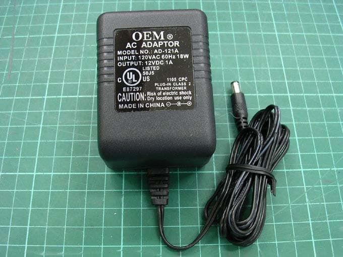
Click to zoom
Application Details
- Equipment Class
- DTS - Digital Transmission System
- Date of Grant
- Dec 20, 2005
- Application Purpose
- Original Equipment
- Date of Application
- Dec 20, 2005
- Equipment Note
- Access Point
- Frequency Range
- 2412.00000000 - 2462.00000000
- Country
- Taiwan
Documents & Files
Document Text
Text extracted from the exhibit documents filed with the FCC. Open a document above to read the original.
Users Manual
ZyXEL G-570S 802.11g Wireless Access Point User’s Guide Version 1.00 11/2005 ZyXEL G-570S User’s Guide 2Copyright Copyright Copyright © 2005 by ZyXEL Communications Corporation. The contents of this publication may not be reproduced in any part or as a whole, transcribed, stored in a retrieval system, translated into any language, or transmitted in any form or by any means, electronic, mechanical, magnetic, optical, chemical, photocopying, manual, or otherwise, without the prior written permission of ZyXEL Communications Corporation. Published by ZyXEL Communications Corporation. All rights reserved. Disclaimer ZyXEL does not assume any liability arising out of the application or use of any products, or software described herein. Neither does it convey any license under its patent rights nor the patent rights of others. ZyXEL further reserves the right to make changes in any products described herein without notice. This publication is subject to change without notice. Trademarks ZyNOS (ZyXEL Network Operating System) is a registered trademark of ZyXEL Communications, Inc. Other trademarks mentioned in this publication are used for identification purposes only and may be properties of their respective owners. ZyXEL G-570S User’s Guide Interference Statements and Certifications3 Interference Statements and Certifications Federal Communications Commission (FCC) Interference Statement This device complies with Part 15 of FCC rules. Operation is subject to the following two conditions: • This device may not cause harmful interference. • This device must accept any interference received, including interference that may cause undesired operations. This equipment has been tested and found to comply with the limits for a Class B digital device pursuant to Part 15 of the FCC Rules. These limits are designed to provide reasonable protection against harmful interference in a commercial environment. This equipment generates, uses, and can radiate radio frequency energy, and if not installed and used in accordance with the instructions, may cause harmful interference to radio communications. If this equipment does cause harmful interference to radio/television reception, which can be determined by turning the equipment off and on, the user is encouraged to try to correct the interference by one or more of the following measures: • Reorient or relocate the receiving antenna. • Increase the separation between the equipment and the receiver. • Connect the equipment into an outlet on a circuit different from that to which the receiver is connected. • Consult the dealer or an experienced radio/TV technician for help. Caution 1To comply with FCC RF exposure compliance requirements, a separation distance of at least 20 cm must be maintained between the antenna of this device and all persons. 2This transmitter must not be co-located or operating in conjunction with any other antenna or transmitter. Notice 1 Changes or modifications not expressly approved by the party responsible for compliance could void the user's authority to operate the equipment. This product has been designed for the WLAN 2.4 GHz network throughout the EC region and Switzerland, with restrictions in France. This Class B digital apparatus complies with Canadian ICES-003. ZyXEL G-570S User’s Guide 4Interference Statements and Certifications Cet appareil numérique de la classe B est conforme à la norme NMB-003 du Canada. Certifications 1Go to www.zyxel.com. 2Select your product from the drop-down list box on the ZyXEL home page to go to that product's page. 3Select the certification you wish to view from this page. ZyXEL G-570S User’s Guide Safety Warnings5 Safety Warnings For your safety, be sure to read and follow all warning notices and instructions. • Do NOT open the device or unit. Opening or removing covers can expose you to dangerous high voltage points or other risks. ONLY qualified service personnel can service the device. Please contact your vendor for further information. • Connect the power cord to the right supply voltage (110V AC in North America or 230V AC in Europe). • Place connecting cables carefully so that no one will step on them or stumble over them. Do NOT allow anything to rest on the power cord and do NOT locate the product where anyone can walk on the power cord. • If you wall mount your device, make sure that no electrical, gas or water pipes will be damaged. • Do NOT install nor use your device during a thunderstorm. There may be a remote risk of electric shock from lightning. • Do NOT expose your device to dampness, dust or corrosive liquids. • Do NOT use this product near water, for example, in a wet basement or near a swimming pool. • Make sure to connect the cables to the correct ports. • Do NOT obstruct the device ventilation slots, as insufficient airflow may harm your device. • Do NOT store things on the device. • Connect ONLY suitable accessories to the device. ZyXEL G-570S User’s Guide 6ZyXEL Limited Warranty ZyXEL Limited Warranty ZyXEL warrants to the original end user (purchaser) that this product is free from any defects in materials or workmanship for a period of up to two years from the date of purchase. During the warranty period, and upon proof of purchase, should the product have indications of failure due to faulty workmanship and/or materials, ZyXEL will, at its discretion, repair or replace the defective products or components without charge for either parts or labor, and to whatever extent it shall deem necessary to restore the product or components to proper operating condition. Any replacement will consist of a new or re-manufactured functionally equivalent product of equal value, and will be solely at the discretion of ZyXEL. This warranty shall not apply if the product is modified, misused, tampered with, damaged by an act of God, or subjected to abnormal working conditions. Note Repair or replacement, as provided under this warranty, is the exclusive remedy of the purchaser. This warra…
Text truncated - open the document above for the full version.
Users Manual
ZyXEL G-570S User’s Guide Chapter 6 Wireless Screens81 6.13 Security Parameters Summary Refer to this table to see what other security parameters you should configure for each authentication method/ key management protocol type. You enter manual keys by first selecting 64-bit WEP,128-bit WEP or 152-bit WEP from the WEP Encryption field and then typing the keys (in ASCII or hexadecimal format) in the key text boxes. MAC address filters are not dependent on how you configure these security features. 6.14 Wireless Client WPA Supplicants A wireless client supplicant is the software that runs on an operating system instructing the wireless client how to use WPA. At the time of writing, the most widely available supplicants are the WPA patch for Windows XP, Funk Software's Odyssey client, and Meetinghouse Data Communications' AEGIS client. The Windows XP patch is a free download that adds WPA capability to Windows XP's built- in "Zero Configuration" wireless client. However, you must run Windows XP to use it. 6.15 Configuring Wireless Security In order to configure and enable wireless security; click SETTINGS > WIRELESS > Security to display the Security screen. This screen varies according to the encryption method you select. Table 16 Wireless Security Relational Matrix AUTHENTICATION METHOD/ KEY MANAGEMENT PROTOCOL ENCRYPTION METHOD ENTER MANUAL KEY IEEE 802.1X Open NoneNoDisable OpenWEPNo Enable with Dynamic WEP Key Ye sEnable without Dynamic WEP Key Ye sDisable SharedWEPNo Enable with Dynamic WEP Key Ye sEnable without Dynamic WEP Key Ye sDisable WPA TKIPNoEnable WPA-PSK TKIPYe sEnable WPA2AESNoEnable WPA2-PSK AESYe sEnable ZyXEL G-570S User’s Guide 82Chapter 6 Wireless Screens 6.15.1 Wireless Security: Disable If you do not enable any wireless security on your device, your network is accessible to any wireless networking device that is within range. Figure 47 Wireless Security: Disable The following table describes the labels in this screen. 6.15.2 Wireless Security: WEP WEP provides a mechanism for encrypting data using encryption keys. Both the AP and the wireless stations must use the same WEP key to encrypt and decrypt data. You can configure up to four 64-bit, 128-bit or 152-bit WEP keys, but only one key can be used at any one time. Table 17 Wireless Security: Disable LABELDESCRIPTION Encryption Method Select Disable to have no wireless LAN security configured. ApplyClick Apply to save your changes back to the device. ResetClick Reset to begin configuring this screen afresh. ZyXEL G-570S User’s Guide Chapter 6 Wireless Screens83 Figure 48 Wireless Security: WEP The following table describes the labels in this screen. Table 18 Wireless Security: WEP LABELDESCRIPTION Encryption Method Select WEP if you want to configure WEP encryption parameters. Authentication Type SelectAuto,Open or Shared from the drop-down list box. WEP EncryptionSelect 64 bit WEP,128 bit WEP or 152 bit WEP to enable data encryption. PassphraseIf you selected 64-bit or 128-bit WEP, you can enter a “passphrase” (password phrase) of up to 32 case-sensitive printable characters and click Generate to have the device create four different WEP keys. GenerateAfter you enter the passphrase, click Generate to have the device generates four different WEP keys automatically. Key 1 to Key 4 If you want to manually set the WEP keys, enter the WEP key in the field provided. Select a WEP key to use for data encryption. The WEP keys are used to encrypt data. Both the device and the wireless stations must use the same WEP key for data transmission. If you chose 64 bit WEP, then enter any 5 ASCII characters or 10 hexadecimal characters ("0-9", "A-F"). If you chose 128 bit WEP, then enter 13 ASCII characters or 26 hexadecimal characters ("0-9", "A-F"). If you chose 152 bit WEP, then enter 16 ASCII characters or 32 hexadecimal characters ("0-9", "A-F"). ApplyClick Apply to save your changes back to the device. ResetClick Reset to begin configuring this screen afresh. ZyXEL G-570S User’s Guide 84Chapter 6 Wireless Screens 6.15.3 Wireless Security: WPA(2)-PSK SelectWPA-PSK,WPA2-PSK or WPA-PSK & WPA2-PSK in the Encryption Method drop down list-box to display the screen displays as next. Figure 49 Wireless Security: WPA(2)-PSK The following table describes the labels in this screen. 6.15.4 Wireless Security: WPA(2) WPA (Wi-Fi Protected Access) is a subset of the IEEE 802.11i standard. WPA2 (IEEE 802.11i) is a wireless security standard that defines stronger encryption, authentication and key management than WPA. Key differences between WPA(2) and WEP are user authentication and improved data encryption. Table 19 Wireless Security: WPA-PSK LABELDESCRIPTION Encryption Method Select WPA-PSK,WPA2-PSK or WPA-PSK & WPA2-PSK if you want to configure a pre-shared key. Choose this option only if your wireless clients support it. Pre-Shared KeyThe encryption mechanisms used for WPA and WPA-PSK are the same. The only difference between the two is that WPA-PSK uses a simple common password, instead of user-specific credentials. Type a pre-shared key from 8 to 63 ASCII characters (including spaces and symbols). This field is case-sensitive. ApplyClick Apply to save your changes back to the device. ResetClick Reset to begin configuring this screen afresh. ZyXEL G-570S User’s Guide Chapter 6 Wireless Screens85 Figure 50 Wireless Security: WPA(2) The following table describes the labels in this screen. Table 20 Wireless Security: WPA(2) LABELDESCRIPTION Encryption Method Select WPA,WPA2 or WPA & WPA2 to configure user authentication and improved data encryption. Note:WPA, WPA2 and IEEE 802.1x wireless security are not available when you use Wireless Client, Bridge or AP+Repeater mode. You can only use WEP keys to encrypt traffic between APs. Authentication Server IP Address Enter the IP address of the external authentication server in dotted decimal notation. Port NumberEnter the port number of the external authentication server. The default port number…
Text truncated - open the document above for the full version.
Cover Letter(s)
Confidentility Letter (Permanent) Attention: Application Examiner Re: Request for confidentiality Applicant: ZyXEL Communications Corporation FCC ID: I88G570S To whom it may concern, Permanent Confidentiality Request is hereby submitted by ZyXEL Communications Corporation to withhold permanently from public review certain portions of the application for equipment certification for the referenced FCC identifiers. This request for confidentiality is made pursuant to 47 CFR 0.457(d) of the FCC Rules. In particular, the following sections of the application are to be kept permanently confidential: • Schematics • Detailed Block diagrams • Detailed Operational/Functional Description Rationale for request for confidentiality: ZyXEL Communications Corporation has invested considerable time and materials in research and development to produce the referenced product. [Permanent confidentiality: Disclosure of the permanently confidential portions of this application to competitors would not only give them significant competitive advantages in developing similar products, but would also disclose successful implementation of unpublished, leading edge technology developed by us.] If you have questions or need further information, please contact the undersigned. Sincerely, Yi Wang ZyXEL Communications Corporation
Cover Letter(s)
American Telecommunications Certification Body Inc. 6731 Whittier Ave, McLean, VA 22101 December 20, 2005 RE: ZyXEL Communications Corporation FCC ID: I88G570S I have a few comments on this Application. Depending on your responses, kindly understand there may be additional comments. 1.) The label for this device shows the wording “Contains WLAN PC Module FCC ID: I88G570S”. This is the label language typical for a Modular Approval according to DA 00-1407. It is not appropriate for a complete stand-alone Access Point. A check at the FCC website shows there is no previously Certified module under FCC ID: I88G570S. Therefore I am a bit confused. Are you seeking Certification on a module that can be used in many different products? Or should FCC ID: I88G570S refer exclusively to the entire Access Point? If the entire Access Point should be approved under this FCC ID, then the label must be changed and the reference to “Contains Inside...” must be removed. 2.) Please confirm if the changes required for EMC compliance shown in the photographs (ferrite in the antenna cable and copper tape on the circuit board) will be carried over into production. 3.) Please provide an MPE Estimation of the RF Exposure levels at 20cm for this device. William H. Graff President and Director of Engineering mailto: [email protected] The items indicated above must be submitted before processing can continue on the above referenced application. Failure to provide the requested information may result in application termination. Correspondence should be considered part of the permanent submission and may be viewed from the Internet after a Grant of Equipment Authorization is issued. Please do not respond to this correspondence using the email reply button. In order for your response to be processed expeditiously, you must submit your documents through the AmericanTCB.com website. Also, please note that partial responses increase processing time and should not be submitted. Any questions about the content of this correspondence should be directed to the sender.
External Photos
Photo 1: External photo of EUT G-570S Photo 2: External photo of EUT G-570S Photo 3: External photo of Adapter Photo 4: External photo of Adapter Photo 5: External photo of Adapter
ID Label/Location Info
FCC ID Label Location 59.20mm 34.20mm
Internal Photos
Photo 1: Internal photo of EUT G-570S Photo 2: Internal photo of EUT G-570S Photo 3: Internal photo of EUT G-570S Photo 4: Internal photo of EUT G-570S Photo 4: Internal photo of EUT G-570S Photo 5: Internal photo of EUT G-570S
RF Exposure Info
FCC ID. : I88G570S Report No.: EME-051170 Page 1 of 5 Maximum Permissible Exposure (MPE) Evaluation Report Report No. : EME-051170 Model No. : G-570S Issued Date : Dec. 13, 2005 Applicant : ZyXEL Communications Corporation 6, Innovation Rd II, Science-Based Industrial Park, Hsin-Chu, Taiwan Test By : Intertek Testing Services Taiwan Ltd. No. 11, Lane 275, Ko-Nan 1 Street, Chia-Tung Li, Shiang-Shan District, Hsinchu City, Taiwan This test report consists of 5 pages in total. It may be duplicated completely for legal use with the allowance of the applicant. It shall not be reproduced except in full, without the written approval of Intertek Laboratory. The test result(s) in this report only applies to the tested sample(s). Kevin Chen Project Engineer Reviewed By Jerry Liu FCC ID. : I88G570S Report No.: EME-051170 Page 2 of 5 Summary of Tests MPE Evaluation meet FCC OET No. 65: 1997/ IEEE C95.1-1999 802.11g Wireless Access Point -Model: G-570S FCC ID: I88G570S Test Reference Results MPE Evaluation FCC Guidelines for Human Exposure IEEE C95.1 Complies FCC ID. : I88G570S Report No.: EME-051170 Page 3 of 5 1. Introduction The EUT operates in the 2.4GHz ISM band. Due to the EUT (include antenna) at its normal operation distance is at least 20 cm from the human body, the EUT was defined as a Mobile Device. The reason to do the MPE Evaluation is to avoid the RF hazard to human body. The maximum output power and gain of the antenna were used to calculate the limited Power density (S) at 20cm distance away from the product. The limit for Maximum Permissible Exposure (MPE) specified in FCC 1.1310 is followed. 2. RF Exposure Limit According to FCC 1.1310: The criteria listed in the following table shall be used to evaluate the environmental impact of human exposure to radio-frequency (RF) radiation as specified in 1.1307(b). Limits for Maximum Permissible Exposure (MPE) Frequency Range (MHz) Electric Field Strength (V/m) Magnetic Field Strength (A/m) Power Density (mW/cm 2 ) Average Time (minutes) (A) Limits for Occupational / Control Exposures 30-300 61.4 0.163 1.0 6 300-1500 - - F/300 6 1500-100,000 - - 5 6 (B) Limits for General Population / Uncontrolled Exposure 30-300 27.5 0.073 0.2 30 300-1500 - - F/1500 30 1500-100,000 - - 1.0 30 F= Frequency in MHz FCC ID. : I88G570S Report No.: EME-051170 Page 4 of 5 3. RF Exposure calculations From §FCC 1.1310 table 1, the maximum permissible RF exposure for an uncontrolled environment is 1mW/(cm 2 ) Power density (S) is calculated by the following formula: S = (P * G)/4πR 2 where, S = Power density (mW/cm 2 ) P = Output power to antenna (mW) R = Distance between radiating structure and observation point (cm) G = Gain of antenna in numeric π = 3.1416 Example: Assume a mobile device operates at 2412MHz and its maximum output power is 50mW, and the maximum gain of antenna is 1 (numeric) /0dBi. then the power density (S) = (50 * 1)/4*π*20 2 = 0.00995 (mW/cm 2 ) FCC ID. : I88G570S Report No.: EME-051170 Page 5 of 5 4. Test results Test Mode: 802.11b(DSSS Modulation) operating mode Channel Channel Frequency (MHz) Maximum antenna gain (numeric) Output power to antenna (mW) Power density (mW/cm 2 ) Limit of power density (mW/cm 2 ) 1 (lowest) 2412 1.60 53.95 0.17207990 1.0 6 (middle) 2437 1.60 53.09 0.016932853 1.0 11 (highest) 2462 1.60 48.75 0.015549991 1.0 Test Mode: 802.11g(OFDM Modulation) operating mode Channel Channel Frequency (MHz) Maximum antenna gain (numeric) Output power to antenna (mW) Power density (mW/cm 2 ) Limit of power density (mW/cm 2 ) 1 (lowest) 2412 1.60 140.60 0.044846664 1.0 6 (middle) 2437 1.60 136.77 0.043624468 1.0 11 (highest) 2462 1.60 126.47 0.040339466 1.0 Test Mode: 802.11g turbo mode Channel Channel Frequency (MHz) Maximum antenna gain (numeric) Output power to antenna (mW) Power density (mW/cm 2 ) Limit of power density (mW/cm 2 ) 6 (middle) 2437 1.60 167.88 0.053546384 1.0 The Notice in Installation Manual has been stated as below: While installing and operating this transmitter, the radio frequency exposure limit of 1mW/(cm*cm) may be exceeded at distances close to the transmitter. therefore, the user must maintain a minimum distance of 20 cm from the device at all time.
Test Report
FCC ID. : I88G570S Report No.: EME-051170 Page 1 of 53 EMC TEST REPORT Report No. : EME-051170 Model No. : G-570S Issued Date : Dec. 13, 2005 Applicant : ZyXEL Communications Corporation 6, Innovation Rd II, Science-Based Industrial Park, Hsin-Chu, Taiwan Test By : Intertek Testing Services Taiwan Ltd. No. 11, Lane 275, Ko-Nan 1 Street, Chia-Tung Li, Shiang-Shan District, Hsinchu City, Taiwan This test report consists of 53 pages in total. It may be duplicated completely for legal use with the allowance of the applicant. It shall not be reproduced except in full, without the written approval of Intertek Laboratory. The test result(s) in this report only applies to the tested sample(s). Kevin Chen Project Engineer Reviewed By Jerry Liu FCC ID. : I88G570S Report No.: EME-051170 Page 2 of 53 Table of Contents Summary of Tests ..............................................................................................................4 1. General information ......................................................................................................5 1.1 Identification of the EUT ........................................................................................5 1.2 Additional information about the EUT....................................................................5 1.3 Antenna description.................................................................................................6 1.4 Peripherals equipment .............................................................................................6 2. Test specifications .........................................................................................................7 2.1 Test standard............................................................................................................7 2.2 Operation mode .......................................................................................................7 2.3 Test equipment ........................................................................................................8 3. Minimum 6dB Bandwidth test ......................................................................................9 3.1 Operating environment............................................................................................9 3.2 Test setup & procedure ............................................................................................9 3.3 Measured data of Minimum 6dB Bandwidth test results ........................................9 4. Maximum Output Power test ......................................................................................17 4.1 Operating environment..........................................................................................17 4.2 Test setup & procedure ..........................................................................................17 4.3 Measured data of Maximum Output Power test results ........................................17 5. Radiated Emission test ................................................................................................19 5.1 Operating environment..........................................................................................19 5.2 Test setup & procedure ..........................................................................................19 5.3 Emission limits ......................................................................................................20 5.4 Radiated spurious emission test data.....................................................................21 5.4.1 Measurement results: frequencies equal to or less than 1 GHz..........................21 5.4.2 Measurement results: frequency above 1GHz ...................................................24 6. Power Spectrum Density test ......................................................................................31 6.1 Operating environment..........................................................................................31 6.2 Test setup & procedure ..........................................................................................31 6.3 Measured data of Power Spectrum Density test results ........................................31 7. Emission on the band edge..........................................................................................40 7.1 Operating environment..........................................................................................40 7.2 Test setup & procedure ..........................................................................................40 FCC ID. : I88G570S Report No.: EME-051170 Page 3 of 53 7.3 Test Result .............................................................................................................41 7.3.1 Conducted Method .............................................................................................41 7.3.2 Radiated Method ................................................................................................49 8. Power Line Conducted Emission test §FCC 15.207 ...................................................50 8.1 Operating environment..........................................................................................50 8.2 Test setup & procedure ..........................................................................................50 8.3 Emission limit .......................................................................................................51 8.4 Uncertainty of Conducted Emission .....................................................................51 8.5 Power Line Conducted Emission test data ............................................................52 FCC ID. : I88G570S Report No.: EME-051170 Page 4 of 53 Summary of Tests 802.11g Wireless Access Point -Model: G-570S FCC ID: I88G570S Test Reference Results Minimum 6dB Bandwidth test 15.247(a)(2) Complies Maximum Output Power test 15.247(b) Complies Radiated Spurious Emission test 15.205, 15.209 Complies Power Spe…
Text truncated - open the document above for the full version.
Test Setup Photos
Photo 1: Conducted Emission Test Set-up photo G-570S Photo 2: Conducted Emission Test Set-up photo G-570S
Test Setup Photos
Photo 1: Radiated Emission Test set-up photo G-570S Photo 2: Radiated Emission Test set-up photo G-570S
Contact Information
Applicant
Emma Bao(Section Manager)
Technical Contact
Intertek Testing Services Taiwan, LtdKevin Chen
[email protected]+886 3 519 1411
No. 11, Ko-Tze-Nan Chia-Tung Li · Hsinchu · Taiwan
Test Firm
Intertek Testing Services Taiwan Ltd.Alpha Liu
Technical Specifications
| # | Rule Parts | Frequency Range | Power Output |
|---|---|---|---|
| 1 | 15C | 2.41 GHz - 2.46 GHz | 168.00 mW |
Other Applications from ZyXEL Communications Corporation
I88EE6601-00
Jul 18, 2024Tri-Band Wireless BE19000 10G Ethernet VoIP Gateway with SFP+ / Tri-Band Wireless BE19000 10G Ethernet VoIP Gateway / Tri-Band Wireless BE19000 10G Ethernet Gateway with SFP+ / Tri-Band Wireless BE19000 10G Ethernet Gateway
Equipment Class
6ID - 15E 6 GHz Low Power Indoor Access Point
I8803935
Oct 17, 2023802.11be (WiFi 7) Triple-Radio Unified Pro Access Point
Equipment Class
DTS - Digital Transmission System
I8803973
Aug 01, 2023802.11ax (WiFi 6) Dual-Radio Wall-Plate Unified Access Point
Equipment Class
NII - Unlicensed National Information Infrastructure TX
I88WX5610-B0
Apr 25, 2023AX7800 WiFi 6E Tri-Band Gigabit Wireless Extender
Equipment Class
DTS - Digital Transmission System
I88EX7710-B0
Apr 16, 2023AX11000 WiFi 6E 10G Ethernet Gateway
Equipment Class
NII - Unlicensed National Information Infrastructure TX