I88MAX200HW2WiMAX Router
ZyXEL Communications Corporation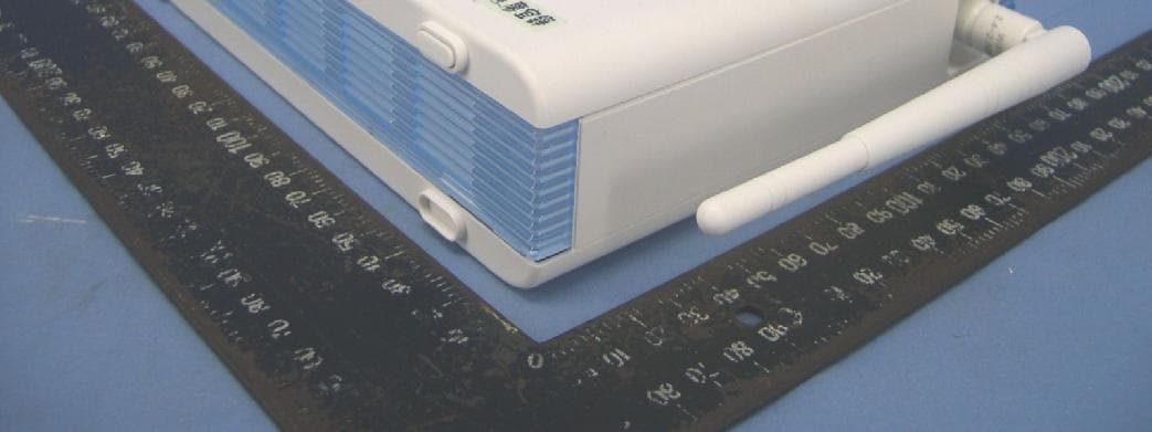
Click to zoom
Application Details
- Equipment Class
- TNB - Licensed Non-Broadcast Station Transmitter
- Date of Grant
- Mar 16, 2008
- Application Purpose
- Original Equipment
- Date of Application
- Feb 24, 2008
- Equipment Note
- WiMAX Router
- Frequency Range
- 2501.00000000 - 2685.00000000
- Country
- Taiwan
Documents & Files
Document Text
Text extracted from the exhibit documents filed with the FCC. Open a document above to read the original.
Users Manual
About This User's Guide MAX-200HW2 Series Users Guide 3 About This User's Guide Congratulations on your purchase of the ZyXEL MAX-200HW2 Series WiMAX WiFi Router with Built-In Switch and VOIP. Your ZyXEL Device allows you to access WiMAX wireless networks, set up a WiFi network and make Voice over Internet (VoIP) phone calls. Your ZyXEL Device is easy to install and configure. Intended Audience This manual is designed to guide you through the configuration of your ZyXEL Device for its various applications. Related Documentation Quick Start Guide The Quick Start Guide is designed to help you get up and running right away. It contains information on setting up your network and configuring for Internet access. Supporting Disk Refer to the included CD for support documents. ZyXEL Web Site Please refer to www.zyxel.com for additional support documentation and product certifications. Users Guide Feedback Help us help you. Send all Users Guide-related comments, questions or suggestions for improvement to the following address, or use e-mail instead. Thank you! The Technical Writing Team, ZyXEL Communications Corp., 6 Innovation Road II, Science-Based Industrial Park, Hsinchu, 300, Taiwan. E-mail: [email protected] Document Conventions MAX-200HW2 Series Users Guide 4 Document Conventions Warnings and Notes These are how warnings and notes are shown in this Users Guide. Warnings tell you about things that could harm you or your ZyXEL Device. Notes tell you other important information (for example, other things you may need to configure or helpful tips) or recommendations. Syntax Conventions The ZyXEL MAX-200HW2 Series may be referred to as the ZyXEL Device, the device, the system or the product in this Users Guide. Product labels, screen names, field labels and field choices are all in bold font. A key stroke is denoted by square brackets and uppercase text, for example, [ENTER] means the enter or return key on your keyboard. Enter means for you to type one or more characters and then press the [ENTER] key. Select or choose means for you to use one of the predefined choices. A right angle bracket ( > ) within a screen name denotes a mouse click. For example, Maintenance > Log > Log Setting means you first click Maintenance in the navigation panel, then the Log sub menu and finally the Log Setting tab to get to that screen. Units of measurement may denote the metric value or the scientific value. For example, k for kilo may denote 1000 or 1024, M for mega may denote 1000000 or 1048576 and so on. e.g., is a shorthand for for instance, and i.e., means that is or in other words. Icons Used in Figures Figures in this Users Guide may use the following generic icons. The ZyXEL Device icon is not an exact representation of your ZyXEL Device. Document Conventions MAX-200HW2 Series Users Guide 5 Table 1 Common Icons ZyXEL DeviceComputerNotebook Wireless SignalWireless Base StationInternet Cloud RouterServerFirewall Safety Warnings MAX-200HW2 Series Users Guide 6 Safety Warnings For your safety, be sure to read and follow all warning notices and instructions. For your safety, be sure to read and follow all warning notices and instructions. Do NOT use this product near water, for example, in a wet basement or near a swimming pool. Do NOT expose your device to dampness, dust or corrosive liquids. Do NOT store things on the device. Do NOT install, use, or service this device during a thunderstorm. There is a remote risk of electric shock from lightning. Connect ONLY suitable accessories to the device. ONLY qualified service personnel should service or disassemble this device. Make sure to connect the cables to the correct ports. Place connecting cables carefully so that no one will step on them or stumble over them. Always disconnect all cables from this device before servicing or disassembling. Use ONLY an appropriate power adaptor or cord for your device. Connect the power adaptor or cord to the right supply voltage (for example, 110V AC in North America or 230V AC in Europe). Do NOT allow anything to rest on the power adaptor or cord and do NOT place the product where anyone can walk on the power adaptor or cord. Do NOT use the device if the power adaptor or cord is damaged as it might cause electrocution. If the power adaptor or cord is damaged, remove it from the power outlet. Do NOT attempt to repair the power adaptor or cord. Contact your local vendor to order a new one. Do not use the device outside, and make sure all the connections are indoors. There is a remote risk of electric shock from lightning. Do NOT obstruct the device ventilation slots, as insufficient airflow may harm your device. Use only No. 26 AWG (American Wire Gauge) or larger telecommunication line cord. Antenna Warning! This device meets ETSI and FCC certification requirements when using the included antenna(s). Only use the included antenna(s). Safety Warnings MAX-200HW2 Series Users Guide 7 This product is recyclable. Dispose of it properly. Safety Warnings MAX-200HW2 Series Users Guide 8 Contents Overview MAX-200HW2 Series Users Guide 9 Contents Overview Introduction ............................................................................................................................31 Getting Started ...........................................................................................................................33 Introducing the Web Configurator ..............................................................................................39 Tutorials and Wizard ..............................................................................................................47 Tutorial .......................................................................................................................................49 Internet Setup Wizard.......................................................................................…
Text truncated - open the document above for the full version.
Users Manual
Chapter 12SIP MAX-200HW2 Series Users Guide 153 12.1.7.2 Use NAT If you know the NAT routers public IP address and SIP port number, you can use the Use NAT feature to manually configure the ZyXEL Device to use a them in the SIP messages. This eliminates the need for STUN or a SIP ALG. You must also configure the NAT router to forward traffic with this port number to the ZyXEL Device. 12.1.7.3 STUN STUN (Simple Traversal of User Datagram Protocol (UDP) through Network Address Translators) allows the ZyXEL Device to find the presence and types of NAT routers and/or firewalls between it and the public Internet. STUN also allows the ZyXEL Device to find the public IP address that NAT assigned, so the ZyXEL Device can embed it in the SIP data stream. STUN does not work with symmetric NAT routers or firewalls. See RFC 3489 for details on STUN. The following figure shows how STUN works. 1The ZyXEL Device (A) sends SIP packets to the STUN server (B). 2The STUN server (B) finds the public IP address and port number that the NAT router used on the ZyXEL Devices SIP packets and sends them to the ZyXEL Device. 3The ZyXEL Device uses the public IP address and port number in the SIP packets that it sends to the SIP server (C). Figure 102 STUN 12.1.7.4 Outbound Proxy Your VoIP service provider may host a SIP outbound proxy server to handle all of the ZyXEL Devices VoIP traffic. This allows the ZyXEL Device to work with any type of NAT router and eliminates the need for STUN or a SIP ALG. Turn off a SIP ALG on a NAT router in front of the ZyXEL Device to keep it from retranslating the IP address (since this is already handled by the outbound proxy server). 12.1.8 Voice Coding A codec (coder/decoder) codes analog voice signals into digital signals and decodes the digital signals back into voice signals. The ZyXEL Device supports the following codecs. G.711 is a Pulse Code Modulation (PCM) waveform codec. PCM measures analog signal amplitudes at regular time intervals (sampling) and converts them into digital bits (quantization). Quantization reads the analog signal and then writes it to the nearest digital value. For this reason, a digital sample is usually slightly different from its analog original (this difference is known as quantization noise). Chapter 12SIP MAX-200HW2 Series Users Guide 154 G.711 provides excellent sound quality but requires 64kbps of bandwidth. G.723 is an Adaptive Differential Pulse Code Modulation (ADPCM) waveform codec. Differential (or Delta) PCM is similar to PCM, but encodes the audio signal based on the difference between one sample and a prediction based on previous samples, rather than encoding the samples actual quantized value. Many thousands of samples are taken each second, and the differences between consecutive samples are usually quite small, so this saves space and reduces the bandwidth necessary. However, DPCM produces a high quality signal (high signal-to-noise ratio or SNR) for high difference signals (where the actual signal is very different from what was predicted) but a poor quality signal (low SNR) for low difference signals (where the actual signal is very similar to what was predicted). This is because the level of quantization noise is the same at all signal levels. Adaptive DPCM solves this problem by adapting the difference signals level of quantization according to the audio signals strength. A low difference signal is given a higher quantization level, increasing its signal-to-noise ratio. This provides a similar sound quality at all signal levels. G.723 provides high quality sound and requires 20 or 40 kbps. G.729 is an Analysis-by-Synthesis (AbS) hybrid waveform codec. It uses a filter based on information about how the human vocal tract produces sounds. The codec analyzes the incoming voice signal and attempts to synthesize it using its list of voice elements. It tests the synthesized signal against the original and, if it is acceptable, transmits details of the voice elements it used to make the synthesis. Because the codec at the receiving end has the same list, it can exactly recreate the synthesized audio signal. G.729 provides good sound quality and reduces the required bandwidth to 8kbps. 12.1.9 PSTN Call Setup Signaling PSTNs (Public Switched Telephone Networks) use DTMF or pulse dialing to set up telephone calls. Dual-Tone Multi-Frequency (DTMF) signaling uses pairs of frequencies (one lower frequency and one higher frequency) to set up calls. It is also known as Touch Tone? Each of the keys on a DTMF telephone corresponds to a different pair of frequencies. Pulse dialing sends a series of clicks to the local phone office in order to dial numbers. 3 12.1.10 MWI (Message Waiting Indication) Enable Message Waiting Indication (MWI) enables your phone to give you a messagewaiting (beeping) dial tone when you have one or more voice messages. Your VoIP service provider must have a messaging system that sends message-waiting-status SIP packets as defined in RFC 3842. 3.The ZyXEL Device supports DTMF at the time of writing. Chapter 12SIP MAX-200HW2 Series Users Guide 155 12.1.11 Custom Tones (IVR) IVR (Interactive Voice Response) is a feature that allows you to use your telephone to interact with the ZyXEL Device. The ZyXEL Device allows you to record custom tones for the Caller Ringing Tone and On Hold Tone functions. The same recordings apply to both the caller ringing and on hold tones. 12.1.11.1 Recording Custom Tones Use the following steps if you would like to create new tones or change your tones: 1Pick up the phone and press **** on your phones keypad and wait for the message that says you are in the configuration menu. 2Press a number from 1101~1108 on your phone followed by the # key. 3Play your desired music or voice recording into the receivers mouthpiece. Press the # key. 4You can continue to add, listen to, or delete tones, or you can hang up the receiver when you are done. 12.1.11.2 Listening to Custom Tones Do…
Text truncated - open the document above for the full version.
Users Manual
Chapter 22Logs MAX-200HW2 Series Users Guide 253 Table 116 FSM Logs: Callee Side LOG MESSAGEDESCRIPTION VoIP Call Start from SIP[SIP Port Number] A VoIP phone call came to the ZyXEL Device from the listed SIP number. VoIP Call Established Ph[Phone Port] <- Outgoing Call Number A VoIP phone call was set up from the listed SIP number to the ZyXEL Device. VoIP Call End Phone[Phone Port] A VoIP phone call that came into the ZyXEL Device has terminated. Table 117 Lifeline Logs LOG MESSAGEDESCRIPTION PSTN Call StartA PSTN call has been initiated. PSTN Call EndA PSTN call has terminated. PSTN Call EstablishedA PSTN call has been set up. Chapter 22Logs MAX-200HW2 Series Users Guide 254 MAX-200HW2 Series Users Guide 255 CHAPTER23 Tools Use these screens to upload new firmware, back up and restore the configuration, and restart the ZyXEL Device. 23.1 Tools Overview 23.1.1 Firmware Contact your service provider for information on available firmware upgrades. Firmware files (usually) use the system model name with a "*.bin" extension, e.g., "ZyXEL Device.bin". The upload process uses HTTP (Hypertext Transfer Protocol) and may take up to two minutes. After a successful upload, the system will reboot. Only use firmware for your ZyXEL Devices specific model. Refer to the label on the back of your ZyXEL Device. 23.2 Tools Screens 23.2.1 Firmware Screen Use this screen to upload new firmware to the ZyXEL Device. To access this screen, click Maintenance > Tools > Firmware. Only use firmware for your ZyXEL Devices specific model. Refer to the label on the bottom of your ZyXEL Device. Chapter 23Tools MAX-200HW2 Series Users Guide 256 Figure 160 Maintenance > Tools > Firmware Each field is described in the following table. 23.2.2 Firmware Upload Screens Do not turn off the device while firmware upload is in progress! When the ZyXEL Device starts to upload firmware, the Firmware Upload in Process screen appears. Figure 161 Firmware Upload In Process Table 118 Maintenance > Tools > Firmware LABELDESCRIPTION File Path Enter the location of the .bin file you want to upload, or click Browse... to find it. You must decompress compressed (.zip) files before you can upload them. Browse... Click this to find the .bin file you want to upload. Upload Click this to begin uploading the selected file. This may take up to two minutes. See Section 23.2.2 on page 256 for more information about this process. Note: Do not turn off the device while firmware upload is in progress! Chapter 23Tools MAX-200HW2 Series Users Guide 257 The process usually takes about two minutes. The device automatically restarts in this time. This causes a temporary network disconnect. In some operating systems, you may see the following icon on your desktop. Figure 162 Network Temporarily Disconnected After two minutes, log in again, and check your new firmware version in the Status screen. You might have to open a new browser window to log in. If the upload is not successful, the following screen appears. Figure 163 Firmware Upload Error ClickReturn to go back to the Firmware screen. 23.2.3 Configuration Screen Use this screen to back up or restore the configuration of the ZyXEL Device. You can also use this screen to reset the ZyXEL Device to the factory default settings. To access this screen, clickMaintenance > Tools > Configuration. Figure 164 Maintenance > Tools > Configuration Chapter 23Tools MAX-200HW2 Series Users Guide 258 Each field is described in the following table. 23.2.4 Restore Configuration Screens Do not turn off the device while configuration file upload is in progress. When the ZyXEL Device has finished restoring the selected configuration file, the following screen appears. Figure 165 Configuration Upload Successful The device now automatically restarts. This causes a temporary network disconnect. In some operating systems, you may see the following icon on your desktop. Table 119 Maintenance > Tools > Configuration LABELDESCRIPTION Backup Configuration BackupClick this to save the ZyXEL Devices current configuration to a file on your computer. Once your device is configured and functioning properly, it is highly recommended that you back up your configuration file before making configuration changes. The backup configuration file is useful if you need to return to your previous settings. Restore Configuration File PathEnter the location of the file you want to upload, or click Browse... to find it. BrowseClick this to find the file you want to upload. UploadClick this to restore the selected configuration file. See Section 23.2.4 on page 258 for more information about this. Note: Do not turn off the device while configuration file upload is in progress. Back to Factory Defaults ResetClick this to clear all user-entered configuration information and return the ZyXEL Device to its factory defaults. There is no warning screen. Chapter 23Tools MAX-200HW2 Series Users Guide 259 Figure 166 Network Temporarily Disconnected If the ZyXEL Devices IP address is different in the configuration file you selected, you may need to change the IP address of your computer to be in the same subnet as that of the default management IP address (192.168.5.1). See your Quick Start Guide or the appendices for details on how to set up your computers IP address. You might have to open a new browser to log in again. If the upload was not successful, a Configuration Upload Error screen appears. Figure 167 Configuration Upload Error ClickReturn to go back to the Configuration screen. 23.2.5 Restart Screen Use this screen to reboot the ZyXEL Device without turning the power off. To access this screen, click Maintenance > Tools > Restart. Figure 168 Maintenance > Tools > Restart This does not affect the ZyXEL Devices configuration. When you click Restart, the following screen appears. Chapter 23Tools MAX-200HW2 Series Users Guide 260 Figure 169 Maintenance > Tools > Restart > In Progress Wait one minute for the device to finish restarting. Then…
Text truncated - open the document above for the full version.
Cover Letter(s)
Federal Communications Commission 7435 Oakland Mills Road Columbia MD 21046 Subject: Request for Confidentiality FCC ID:I88MAX200HW2 To Whom It May Concern: Pursuant to the provisions of Sections 0.457 and 0.459 of the Commission’s rules (47 CFR §§ 0.457, 0.459), we are requesting the Commission to withhold the following attachments as confidential document from public disclosure indefinitely. Schematic Diagram Block Diagram Operation Description Parts List / Tune-Up Procedures Above mentioned document contains detailed system and equipment description are considered as proprietary information in operation of the equipment. The public disclosure of above documents might be harmful to our company and would give competitor an unfair advantage in the market. In additional to above mentioned documents, pursuant to Public Notice DA 04-1705 of the Commission’s policy, in order to comply with the marketing regulations in 47 CFR §2.803 and the importation rules in 47 CFR §2.1204, while ensuring that business sensitive information remains confidential until the actual marketing of newly authorized devices. We are requesting the commission to grant short-term confidentiality request on the following attachments for 180 days after the grant letter released External Photos Internal Photos Test Setup Photos User’s Manual It is our understanding that all measurement test reports, FCC ID label format and correspondent during certification review process cannot be granted as confidential documents and those information will be available for public review once the grant of equipment authorization is issued. Best Regards 2008/02/01 ------------------------------------------------------------------------------ Name: Yi Wang Title / Dept. Section Manager / EMC/Safety Engineering Dept. Company Name: ZyXEL Communications Corporation TEL: 886-3-5783942 ext.6780 E-mail : [email protected]
Cover Letter(s)
TCB GRANT OF EQUIPMENT AUTHORIZATION TCB Certification Issued Under the Authority of the Federal Communications Commission By: Curtis-Straus LLC 527 Great Road Littleton, MA 01460 Date of Grant: 05/18/2006 Application Dated: 05/18/2006 ZyXEL Communications Corporation No. 6, Innovation Rd. II Science Based Industrial Park Hsin-Chu, Taiwan Attention: Wang Yi , Engineer NOT TRANSFERABLE EQUIPMENT AUTHORIZATION is hereby issued to the named GRANTEE, and is VALID ONLY for the equipment identified hereon for use under the Commission's Rules and Regulations listed below. FCC IDENTIFIER: I88G-620 Name of Grantee: ZyXEL Communications Corporation Equipment Class: Digital Transmission System Notes:802.11 gWireless MiniPCI Card Grant Notes FCC Rule Parts Frequency Range (MHZ) Output Watts Frequency Tolerance Emission Designator 15C2412.0 - 2462.0 0.112 Output power listed is conducted. Modular Approval for mobile RF Exposure conditions, the antenna(s) used for this transmitter must be installed to provide a separation distance of at least 20cm from all persons and must not be co-located or operating in conjunction with any other antenna or transmitter. Approval is limited to OEM installation only. OEM integrators must be provided with antenna installation instructions. OEM integrators and end-Users must be provided with transmitter operation conditions for satisfying RF exposure compliance. This grant is valid only when the device is sold to OEM integrators and the OEM integrators are instructed to ensure that the end user has no manual instructions to remove or install the device. The only antennas approved for use with this module are those documented in the filings under this FCC ID.
External Photos
Page 1 CONSTRUCTION PHOTOS OF EUT
ID Label/Location Info
FCC ID:I88MAX200HW2 FCC LABEL LOCATION The label will be permanently affixed at a conspicuous location on the device. Label location
Internal Photos
Page 2 Page 3 Page 4 Page 5 Page 6 Page 7 Page 8 Page 9 Page 10 Page 11 Page 12 Page 13 Page 14 Page 15
RF Exposure Info
Report No.: SA961108H05 1 RF EXPOSURE REPORT REPORT NO.: SA961108H05 MODEL NO.: MAX-200HW2 ACCORDING: FCC Guidelines for Human Exposure IEEE C95.1 APPLICANT: ZyXEL Communications Corporation ADDRESS: No. 6, Innovation Road II, Science-Park, Hsin-Chu, 300, Taiwan ISSUED BY: Advance Data Technology Corporation LAB LOCATION: No. 81-1, Lu Liao Keng, 9 Ling, Wu Lung Tsuen, Chiung Lin Hsiang, Hsin Chu Hsien, Taiwan, R.O.C. Report No.: SA961108H05 2 RF Exposure Measurement 1. Introduction In this document, we try to prove the safety of radiation harmfulness to the human body for our product. The limit for Maximum Permissible Exposure (MPE) specified in FCC 1.1310 is followed. The Gain of the antenna used in this product is measured in a Fully Anechoic Chamber (FAC) calibrated for antenna measurement in ADT, and also the maximum total power input to the antenna is measured. Through the Friis transmission formula and the maximum gain of the antenna, we can calculate the distance, away from the product, where the limit of MPE is reached. Although the Friis transmission formula is a far field assumption, the calculated result of that is an over-prediction for near field power density. We will take that as the worst case to specify the safety range. 2. RF Exposure Limit According to FCC 1.1310: The criteria listed in the following table shall be used to evaluate the environmental impact of human exposure to radio-frequency (RF) radiation as specified in 1.1307(b) LIMITS FOR MAXIMUM PERMISSIBLE EXPOSURE (MPE) Frequency Range (MHz) Electric Field Strength (V/m) Magnetic Field Strength (A/m) Power Density (mW/cm 2 ) Average Time (minutes) (A)Limits For Occupational / Control Exposures 300-1500 ... ... F/300 6 1500-100,000 ... ... 5 6 (B)Limits For General Population / Uncontrolled Exposure 300-1500 ... ... F/1500 6 1500-100,000 ... ... 1.0 30 F = Frequency in MHz Report No.: SA961108H05 3 3. Friis Formula Friis transmission formula : Pd = (Pout*G) / (4*pi*r 2 ) where Pd = power density in mW/cm 2 Pout = output power to antenna in mW G = gain of antenna in linear scale Pi = 3.1416 R = distance between observation point and center of the radiator in cm Pd is the limit of MPE, 1 mW/cm 2 . If we know the maximum Gain of the antenna and the total power input to the antenna, through the calculation, we will know the MPE value at distance 20cm. Ref. : David K. Cheng, Field and Wave Electromagnetics, Second Edition, Page 640, Eq. (11-133). 4. EUT Operating condition The software provided by Manufacturer enabled the EUT to transmit and receive data at lowest, middle and highest channel individually. 5. Classification The antenna of this product, under normal use condition, is at least 20cm away from the body of the user. Warning statement to the user for keeping at least 20cm or more separation distance with the antenna should be included in users manual. So, this device is classified as Mobile Device Report No.: SA961108H05 4 6. Test Results 6.1 Antenna Gain There is one antenna provided to this EUT, please refer to the following table: Gain (dBi) Cable Loss (dB) Net Gain (dB) Antenna Type Connector 10.5 2.0 8.5 Directional Panel SMA Plug 6.2 Output Power Into Antenna & RF Exposure value at distance 20cm: For WiMax: For Part 802.11b: Channel Channel Frequency (MHz) Output Power to Antenna (mW) Power Density (mW/cm 2 ) Limit of Power Density (mW/cm 2 ) Low 2501.0 220.800 0.311 1.0 Middle 2587.5 256.448 0.361 1.0 High 2685.0 225.944 0.318 1.0 802.11g wireless MiniPCI card : Channel Channel Frequency (MHz) Output Power to Antenna (mW) Power Density (mW/cm 2 ) Limit of Power Density (mW/cm 2 ) 6 2437 112.202 0.405 1.0 NOTE: Limit of power density = 824.7 (MHz) / 1500 = 0.5498. CONCULSION: Both of the WLAN and GSM can transmit simultaneously, the formula of calculated the MPE is: CPD 1 / LPD 1 + CPD 2 / LPD 2 + ......etc. < 1 CPD = Calculation power density LPD = Limit of power density Therefore, the worst-case situation is 0.361 / 1 + 0.409 / 1 = 0.77, which is less than “1”. This confirmed that the device comply with FCC 1.1310 MPE limit.
RF Exposure Info
Report No.: SA961108H05 1 RF EXPOSURE REPORT REPORT NO.: SA961108H05 MODEL NO.: MAX-200HW2 ACCORDING: FCC Guidelines for Human Exposure IEEE C95.1 APPLICANT: ZyXEL Communications Corporation ADDRESS: No. 6, Innovation Road II, Science-Park, Hsin-Chu, 300, Taiwan ISSUED BY: Advance Data Technology Corporation LAB LOCATION: No. 81-1, Lu Liao Keng, 9 Ling, Wu Lung Tsuen, Chiung Lin Hsiang, Hsin Chu Hsien, Taiwan, R.O.C. Report No.: SA961108H05 2 RF Exposure Measurement 1. Introduction In this document, we try to prove the safety of radiation harmfulness to the human body for our product. The limit for Maximum Permissible Exposure (MPE) specified in FCC 1.1310 is followed. The Gain of the antenna used in this product is measured in a Fully Anechoic Chamber (FAC) calibrated for antenna measurement in ADT, and also the maximum total power input to the antenna is measured. Through the Friis transmission formula and the maximum gain of the antenna, we can calculate the distance, away from the product, where the limit of MPE is reached. Although the Friis transmission formula is a far field assumption, the calculated result of that is an over-prediction for near field power density. We will take that as the worst case to specify the safety range. 2. RF Exposure Limit According to FCC 1.1310: The criteria listed in the following table shall be used to evaluate the environmental impact of human exposure to radio-frequency (RF) radiation as specified in 1.1307(b) LIMITS FOR MAXIMUM PERMISSIBLE EXPOSURE (MPE) Frequency Range (MHz) Electric Field Strength (V/m) Magnetic Field Strength (A/m) Power Density (mW/cm 2 ) Average Time (minutes) (A)Limits For Occupational / Control Exposures 300-1500 ... ... F/300 6 1500-100,000 ... ... 5 6 (B)Limits For General Population / Uncontrolled Exposure 300-1500 ... ... F/1500 6 1500-100,000 ... ... 1.0 30 F = Frequency in MHz Report No.: SA961108H05 3 3. Friis Formula Friis transmission formula : Pd = (Pout*G) / (4*pi*r 2 ) where Pd = power density in mW/cm 2 Pout = output power to antenna in mW G = gain of antenna in linear scale Pi = 3.1416 R = distance between observation point and center of the radiator in cm Pd is the limit of MPE, 1 mW/cm 2 . If we know the maximum Gain of the antenna and the total power input to the antenna, through the calculation, we will know the MPE value at distance 20cm. Ref. : David K. Cheng, Field and Wave Electromagnetics, Second Edition, Page 640, Eq. (11-133). 4. EUT Operating condition The software provided by Manufacturer enabled the EUT to transmit and receive data at lowest, middle and highest channel individually. 5. Classification The antenna of this product, under normal use condition, is at least 20cm away from the body of the user. Warning statement to the user for keeping at least 20cm or more separation distance with the antenna should be included in users manual. So, this device is classified as Mobile Device Report No.: SA961108H05 4 6. Test Results 6.1 Antenna Gain There is one antenna provided to this EUT, please refer to the following table: Gain (dBi) Cable Loss (dB) Net Gain (dB) Antenna Type Connector 10.5 2.0 8.5 Directional Panel SMA Plug 6.2 Output Power Into Antenna & RF Exposure value at distance 20cm: For WiMax: Channel Channel Frequency (MHz) Output Power to Antenna (mW) Power Density (mW/cm 2 ) Limit of Power Density (mW/cm 2 ) Low 2498.5 232.809 0.328 1.0 Middle 2587.5 259.418 0.365 1.0 High 2687.5 234.423 0.330 1.0 802.11g wireless MiniPCI card : Channel Channel Frequency (MHz) Output Power to Antenna (mW) Power Density (mW/cm 2 ) Limit of Power Density (mW/cm 2 ) 6 2437 112.202 0.409 1.0 NOTE: Limit of power density = 824.7 (MHz) / 1500 = 0.5498. CONCULSION: Both of the WLAN and GSM can transmit simultaneously, the formula of calculated the MPE is: CPD 1 / LPD 1 + CPD 2 / LPD 2 + ......etc. < 1 CPD = Calculation power density LPD = Limit of power density Therefore, the worst-case situation is 0.365 / 1 + 0.409 / 1 = 0.774, which is less than “1”. This confirmed that the device com…
Text truncated - open the document above for the full version.
Contact Information
Applicant
Emma Bao(Section Manager)
Technical Contact
Advance Data Technology Corporation (Hsin Chu)Eric Lin
[email protected]886-3-593-5343
81-1 Luliaoken, 9th Lin, Wulung Tsuen Chiunglin · Hsinchu · Taiwan
Non-Technical Contact
Advance Data Technology CorporationEric Lin
[email protected]886-3-593-5343
Test Firm
Bureau Veritas CPS (H.K.) Ltd. Taoyuan BranchRichard Chen
Technical Specifications
| # | Rule Parts | Frequency Range | Power Output | Emission | Tolerance |
|---|---|---|---|---|---|
| 2 | 27 | 2.50 GHz - 2.69 GHz | 256.00 mW | 9M08G9W | 3.02 ppm |
Other Applications from ZyXEL Communications Corporation
I88EE6601-00
Jul 18, 2024Tri-Band Wireless BE19000 10G Ethernet VoIP Gateway with SFP+ / Tri-Band Wireless BE19000 10G Ethernet VoIP Gateway / Tri-Band Wireless BE19000 10G Ethernet Gateway with SFP+ / Tri-Band Wireless BE19000 10G Ethernet Gateway
Equipment Class
6ID - 15E 6 GHz Low Power Indoor Access Point
I8803935
Oct 17, 2023802.11be (WiFi 7) Triple-Radio Unified Pro Access Point
Equipment Class
DTS - Digital Transmission System
I8803973
Aug 01, 2023802.11ax (WiFi 6) Dual-Radio Wall-Plate Unified Access Point
Equipment Class
NII - Unlicensed National Information Infrastructure TX
I88WX5610-B0
Apr 25, 2023AX7800 WiFi 6E Tri-Band Gigabit Wireless Extender
Equipment Class
DTS - Digital Transmission System
I88EX7710-B0
Apr 16, 2023AX11000 WiFi 6E 10G Ethernet Gateway
Equipment Class
NII - Unlicensed National Information Infrastructure TX