I88NBG4104Wireless N-lite Managed Router
ZyXEL Communications Corporation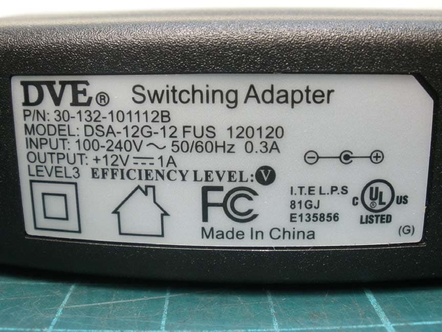
Click to zoom
Application Details
- Equipment Class
- DTS - Digital Transmission System
- Date of Grant
- Jan 16, 2012
- Application Purpose
- Original Equipment
- Date of Application
- Dec 18, 2011
- Equipment Note
- Wireless N-lite Managed Router
- Frequency Range
- 2422.00000000 - 2452.00000000
- Country
- Taiwan
Documents & Files
Document Text
Text extracted from the exhibit documents filed with the FCC. Open a document above to read the original.
Users Manual
www.zyxel.com www.zyxel.com NBG4104 Wireless N-lite Managed Router Copyright © 2011 ZyXEL Communications Corporation Firmware Version 1.0 Edition 1, 11/2011 Default Login Details IP Addresshttp://192.168.1.1 User Nameadmin Password1234 About This User's Guide NBG4104 User’s Guide 3 About This User's Guide Intended Audience This manual is intended for people who want to configure the NBG4104 using the Web Configurator. Tips for Reading User’s Guides On-Screen When reading a ZyXEL User’s Guide On-Screen, keep the following in mind: • If you don’t already have the latest version of Adobe Reader, you can download it from http:// www.adobe.com. • Use the PDF’s bookmarks to quickly navigate to the areas that interest you. Adobe Reader’s bookmarks pane opens by default in all ZyXEL User’s Guide PDFs. • If you know the page number or know vaguely which page-range you want to view, you can enter a number in the toolbar in Reader, then press [ENTER] to jump directly to that page. • Type [CTRL]+[F] to open the Adobe Reader search utility and enter a word or phrase. This can help you quickly pinpoint the information you require. You can also enter text directly into the toolbar in Reader. • To quickly move around within a page, press the [SPACE] bar. This turns your cursor into a “hand” with which you can grab the page and move it around freely on your screen. • Embedded hyperlinks are actually cross-references to related text. Click them to jump to the corresponding section of the User’s Guide PDF. Related Documentation •Quick Start Guide The Quick Start Guide is designed to help you get your NBG4104 up and running right away. It contains information on setting up your network and configuring for Internet access. •Support Disc Refer to the included CD for support documents. Document Conventions NBG4104 User’s Guide 4 Document Conventions Warnings and Notes These are how warnings and notes are shown in this User’s Guide. Warnings tell you about things that could harm you or your device. Note: Notes tell you other important information (for example, other things you may need to configure or helpful tips) or recommendations. Syntax Conventions • The NBG4104 may be referred to as the “NBG4104”, the “device”, the “product” or the “system” in this User’s Guide. • Product labels, screen names, field labels and field choices are all in bold font. • A key stroke is denoted by square brackets and uppercase text, for example, [ENTER] means the “enter” or “return” key on your keyboard. • “Enter” means for you to type one or more characters and then press the [ENTER] key. “Select” or “choose” means for you to use one of the predefined choices. • A right angle bracket ( > ) within a screen name denotes a mouse click. For example, Maintenance > Log > Log Setting means you first click Maintenance in the navigation panel, then the Log sub menu and finally the Log Setting tab to get to that screen. • Units of measurement may denote the “metric” value or the “scientific” value. For example, “k” for kilo may denote “1000” or “1024”, “M” for mega may denote “1000000” or “1048576” and so on. • “e.g.,” is a shorthand for “for instance”, and “i.e.,” means “that is” or “in other words”. Document Conventions NBG4104 User’s Guide 5 Icons Used in Figures Figures in this User’s Guide may use the following generic icons. The NBG4104 icon is not an exact representation of your device. NBG4104ComputerNotebook computer ServerDSLAMFirewall Tel ep ho n eSwitchRouter Modem Safety Warnings NBG4104 User’s Guide 6 Safety Warnings • Do NOT use this product near water, for example, in a wet basement or near a swimming pool. • Do NOT expose your device to dampness, dust or corrosive liquids. • Do NOT store things on the device. • Do NOT install, use, or service this device during a thunderstorm. There is a remote risk of electric shock from lightning. • Connect ONLY suitable accessories to the device. • Do NOT open the device or unit. Opening or removing covers can expose you to dangerous high voltage points or other risks. ONLY qualified service personnel should service or disassemble this device. Please contact your vendor for further information. • Make sure to connect the cables to the correct ports. • Place connecting cables carefully so that no one will step on them or stumble over them. • Always disconnect all cables from this device before servicing or disassembling. • Use ONLY an appropriate power adaptor or cord for your device. • Connect the power adaptor or cord to the right supply voltage (for example, 110V AC in North America or 230V AC in Europe). • Do NOT allow anything to rest on the power adaptor or cord and do NOT place the product where anyone can walk on the power adaptor or cord. • Do NOT use the device if the power adaptor or cord is damaged as it might cause electrocution. • If the power adaptor or cord is damaged, remove it from the power outlet. • Do NOT attempt to repair the power adaptor or cord. Contact your local vendor to order a new one. • Do not use the device outside, and make sure all the connections are indoors. There is a remote risk of electric shock from lightning. • Do NOT obstruct the device ventilation slots, as insufficient airflow may harm your device. • Antenna Warning! This device meets ETSI and FCC certification requirements when using the included antenna(s). Only use the included antenna(s). • If you wall mount your device, make sure that no electrical lines, gas or water pipes will be damaged. Your product is marked with this symbol, which is known as the WEEE mark. WEEE stands for Waste Electronics and Electrical Equipment. It means that used electrical and electronic products should not be mixed with general waste. Used electrical and electronic equipment should be treated separately. Contents Overview NBG4104 User’s Guide 7 Contents Overview User’s Guide ........................................................................................................................... 15 Introduc…
Text truncated - open the document above for the full version.
Cover Letter(s)
Attestation for FCC Declaration of Conformity FCC ID: I88NBG4104 Data: 2011/11/15 Please be notified that we, the undersigned, ZyXEL Communications Corporation declares that the product which bears the above FCC ID is also compliant with the FCC requirements for DoC. The test report number supporting the DoC is TS11040101-EME& TS11040101-EME(R1). Testing in regards to this report was done by Intertek Testing Service Taiwan Ltd., located at No. 11, Lane 275, Ko Nan 1st Street, Shiang-Shan District, Hsinchu Taiwan, which has been accredited in accordance to all of the requirements of 47CFR 2.948 (d) and (e) of the FCC rules and KDB349827.
External Photos
External photo of EUT Antenna External photo of EUT Antenna Antenna Connector External photo of EUT Model: MU05-N120050-A1 Model: MU05-N120050-A1 External photo of EUT Model: DSA-12G-12 FUS 120120 Model: DSA-12G-12 FUS 120120
ID Label/Location Info
Label FCC ID Label Location
Internal Photos
Internal photo of EUT Internal photo of EUT RF Part Internal photo of EUT RX Antenna
RF Exposure Info
FCC ID. : I88NBG4104 Report No.: TS11040103-EME Page 1 of 7 Maximum Permissible Exposure (MPE) Evaluation Report Report No. : TS11040103-EME Model No. : NBG4104, NBG-417N v2, HGW-500HNR-R, HGW-500HN-R Issued Date : Aug. 23, 2011 Applicant: ZyXEL Communications Corporation No. 6, Innovation Rd II, Science-Based Industrial Park, Hsin-Chu, Taiwan Test Method/ Standard: FCC 1.1310 Test By: Intertek Testing Services Taiwan Ltd. No. 11, Lane 275, Ko-Nan 1 Street, Chia-Tung Li, Shiang-Shan District, Hsinchu City, Taiwan It may be duplicated completely for legal use with the allowance of the applicant. It shall not be reproduced except in full, without the written approval of Intertek Laboratory. The test result(s) in this report only applies to the tested sample(s). The test report was prepared by: Sign on File Jill Chen / Assistant These measurements were taken by: Sign on File Terry Hsu / Engineer The test report was reviewed by: Name Jimmy Yang Title Engineer FCC ID. : I88NBG4104 Report No.: TS11040103-EME Page 2 of 7 Table of Contents Summary of Tests ............................................................................................................. 3 1. Introduction .................................................................................................................. 4 2. RF Exposure Limit ....................................................................................................... 4 3. RF Exposure calculations ............................................................................................. 5 4 Description of EUT ....................................................................................................... 6 5. Test results .................................................................................................................... 7 FCC ID. : I88NBG4104 Report No.: TS11040103-EME Page 3 of 7 Summary of Tests MPE Evaluation meet FCC OET No. 65: 1997, IEEE C95.1-2005 Wireless N-lite Managed Router - Model: NBG4104 FCC ID: I88NBG4104 Test Reference Results MPE Evaluation FCC Guidelines for Human Exposure IEEE C95.1 Complies FCC ID. : I88NBG4104 Report No.: TS11040103-EME Page 4 of 7 1. Introduction The EUT operates in the 2.4 GHz ISM band. Due to the EUT (include antenna) at its normal operation distance is at least 20 cm from the human body, the EUT was defined as a Mobile Device. The reason to do the MPE Evaluation is to avoid the RF hazard to human body. The maximum output power and gain of the antenna were used to calculate the limited Power density (S) at 20 cm distance away from the product. The limit for Maximum Permissible Exposure (MPE) specified in FCC 1.1310 and Safety Code 6 are followed. According to 1.1307 (b)(1), systems operating under the provisions of this section shall be operated in a manner that ensure that the public is not exposed to radio frequency energy level in excess of the Commission’s guideline. 2. RF Exposure Limit According to FCC 1.1310: The criteria listed in the following table shall be used to evaluate the environmental impact of human exposure to radio-frequency (RF) radiation as specified in 1.1307(b). Limits for Maximum Permissible Exposure (MPE) Frequency Range (MHz) Electric Field Strength (V/m) Magnetic Field Strength (A/m) Power Density (mW/cm 2 ) Average Time (minutes) (A) Limits for Occupational / Control Exposures 30-300 61.4 0.163 1.0 6 300-1500 - - F/300 6 1500-100,000 - - 5 6 (B) Limits for General Population / Uncontrolled Exposure 30-300 27.5 0.073 0.2 30 300-1500 - - F/1500 30 1500-100,000 - - 1.0 30 F= Frequency in MHz FCC ID. : I88NBG4104 Report No.: TS11040103-EME Page 5 of 7 3. RF Exposure calculations From §FCC 1.1310 table 1, the maximum permissible RF exposure for an uncontrolled environment is 1 mW/(cm 2 ) (or 10 W/m 2 )* Power density (S) is calculated by the following formula: S = (P * G)/4πR 2 where, S = Power density (mW/cm 2 ) P = Output power to antenna (mW) R = Distance between radiating structure and observation point (cm) G = Gain of antenna in numeric π = 3.1416 Example: Assume a mobile device operates at 2412MHz and its maximum output power is 50mW, and the maximum gain of antenna is 1 (numeric) /0dBi. then the power density (S) = (50 * 1)/4*π*20 2 = 0.00995 (mW/cm 2 ) (or = 0.0995 W/m 2 ) FCC ID. : I88NBG4104 Report No.: TS11040103-EME Page 6 of 7 4 Description of EUT The EUT is Wireless N-lite Managed Router, and was defined as information technology equipment. For more detail features, please refer to User's manual as file name “Installation guide.pdf” The customer confirmed NBG-417N v2, HGW-500HNR-R and HGW-500HN-R are series model to NBG4104 (EUT), the different model numbers are served as marketing strategy. 4.1 Antenna description Antenna The antenna is affixed to the EUT using a unique connector, which allows for replacement of a broken antenna, but DOES NOT use a standard antenna jack or electrical connector. Antenna Gain : 2 dBi Antenna Type : Dipole antenna Connector Type : SMA reverse 4.2 Adapter information The EUT will be supplied with a power supply from below list: No. BrandModel no. Specification Adapter 1 LEI MU05-N120050-A1 I/P: 100-240Vac, 50/60Hz, 0.5A O/P: 12Vdc, 0.5A Adapter 2 DVE DSA-12G-12 FUS 120120 I/P: 100-240Vac, 50/60Hz, 0.3A O/P: 12Vdc, 0.5A FCC ID. : I88NBG4104 Report No.: TS11040103-EME Page 7 of 7 5. Test results EUT : NBG4104 Mode Channel Frequency (MHz) Antenna gain (numeric) Output power to antenna (mW) Power density (mW/cm 2 ) Limit of power density (mW/cm 2 ) 2412 2.00 71.78 0.028560127 1.0 2437 2.00 69.34 0.027590536 1.0 802.11b 2462 2.00 74.47 0.029631944 1.0 2412 2.00 202.77 0.080678932 1.0 2437 2.00 194.09 0.077225395 1.0 802.11g 2462 2.00 190.11 0.075641501 1.0 2412 2.00 160.32 0.063791107 1.0 2437 2.00 153.82 0.061201229 1.0 802.11n HT20 2462 2.00 139.64 0.055559732 1.0 2422 2.00 167.11 0.066490583 1.0 2437 2.00 153.11 0.060920034 1.0 802.11n HT40 2452 2.00 146.22 0.058178181 1.0 The Notice in Installation Manual has …
Text truncated - open the document above for the full version.
Test Report
FCC ID. : I88NBG4104 Report No.: TS11040102-EME Page 1 of 78 EMC TEST REPORT Report No. : TS11040102-EME Model No. : NBG4104, NBG-417N v2, HGW-500HNR-R, HGW-500HN-R Issued Date : Aug. 23, 2011 Applicant: ZyXEL Communications Corporation No. 6, Innovation Rd II, Science-Based Industrial Park, Hsin-Chu, Taiwan Test Method/ Standard: CFR 47 FCC Part 15.247 & ANSI C63.4 2003 Test By: Intertek Testing Services Taiwan Ltd. No. 11, Lane 275, Ko-Nan 1 Street, Chia-Tung Li, Shiang-Shan District, Hsinchu City, Taiwan It may be duplicated completely for legal use with the allowance of the applicant. It shall not be reproduced except in full, without the written approval of Intertek Laboratory. The test result(s) in this report only applies to the tested sample(s). The test report was prepared by: Sign on File Jill Chen / Assistant These measurements were taken by: Sign on File Terry Hsu / Engineer The test report was reviewed by: Name Jimmy Yang Title Engineer FCC ID. : I88NBG4104 Report No.: TS11040102-EME Page 2 of 78 Table of Contents 1. Summary of Test Data................................................................................................. 3 2. General Information .................................................................................................... 4 3. Maximum 6 dB Bandwidth .......................................................................................... 7 4. 99 % Occupied Bandwidth ........................................................................................ 15 5. Maximum Output Power............................................................................................ 21 6. Power Spectral Density ............................................................................................. 21 7. RF Antenna conducted Spurious............................................................................... 21 8. Radiated Spurious Emission..................................................................................... 21 9. Emission on Band Edge............................................................................................ 21 10. AC power line conducted emission......................................................................... 21 Appendix A: Test Equipment List................................................................................... 21 FCC ID. : I88NBG4104 Report No.: TS11040102-EME Page 3 of 78 1. Summary of Test Data Test/Requirement Description Applicable Rule Result Minimum 6 dB Bandwidth 15.247(a)(2) Pass Maximum Output Power 15.247(b) Pass Power Spectral Density 15.247(e) Pass RF Antenna Conducted Spurious 15.247(d) Pass Radiated Spurious Emission 15.247(d), 15.205, 15.209 Pass Emission on the Band Edge 15.247(d) Pass AC Power Line Conducted Emission 15.207 Pass FCC ID. : I88NBG4104 Report No.: TS11040102-EME Page 4 of 78 2. General Information Identification of the EUT Product: Wireless N-lite Managed Router Model No.: NBG4104 FCC ID.: I88NBG4104 Frequency Range: 1. 2412 MHz ~ 2462 MHz for 802.11b, 802.11g, 802.11n HT20 2. 2422 MHz ~ 2452 MHz for 802.11n HT40 Channel Number: 1. 11 channels for 2412 MHz ~ 2462 MHz 2. 7 channels for 2422 MHz ~ 2452 MHz Rated Power: DC 12 V from Adapter Power Cord: N/A Data Cable: 1. RJ-45 UTP Cat.5 10 meter × 4 2. RJ-45 STP Cat.5 10 meter × 1 Sample Received: May 16, 2011 Test Date(s): May 17, 2011 ~ Aug. 16, 2011 Note 1: This report is for the exclusive use of Intertek's Client and is provided pursuant to the agreement between Intertek and its Client. Intertek's responsibility and liability are limited to the terms and conditions of the agreement. Intertek assumes no liability to any party, other than to the Client in accordance with the agreement, for any loss, expense or damage occasioned by the use of this report. Only the Client is authorized to permit copying or distribution of this report and then only in its entirety. Any use of the Intertek name or one of its marks for the sale or advertisement of the tested material, product or service must first be approved in writing by Intertek. The observations and test results in this report are relevant only to the sample tested. This report by itself does not imply that the material, product, or service is or has ever been under an Intertek certification program. Note 2: When determining the test conclusion, the Measurement Uncertainty of test has been considered. FCC ID. : I88NBG4104 Report No.: TS11040102-EME Page 5 of 78 Description of EUT The EUT is Wireless N-lite Managed Router, and was defined as information technology equipment. For more detail features, please refer to User's manual as file name “Installation guide.pdf” The customer confirmed NBG-417N v2, HGW-500HNR-R and HGW-500HN-R are series model to NBG4104 (EUT), the different model numbers are served as marketing strategy. Antenna description Antenna The antenna is affixed to the EUT using a unique connector, which allows for replacement of a broken antenna, but DOES NOT use a standard antenna jack or electrical connector. Antenna Gain : 2 dBi Antenna Type : Dipole antenna Connector Type : SMA reverse Adapter information The EUT will be supplied with a power supply from below list: No. Brand Model no. Specification Adapter 1 LEI MU05-N120050-A1 I/P: 100-240Vac, 50/60Hz, 0.5A O/P: 12Vdc, 0.5A Adapter 2 DVE DSA-12G-12 FUS 120120 I/P: 100-240Vac, 50/60Hz, 0.3A O/P: 12Vdc, 0.5A Peripherals equipment Peripherals Brand Model No. Serial No. Notebook PC DELL Latitude D610 2YWZK1S ZyWALL ZyXEL 1050 N/A Muti-mode converterVOLKTEK NXF-742 N/A FCC ID. : I88NBG4104 Report No.: TS11040102-EME Page 6 of 78 Operation mode The EUT was supplied with 12 Vdc from adapter (Test voltage: 120Vac, 60Hz) and it was run in TX mode that was controlled by “QA” program. The EUT was transmitted continuously during the test. With individual verifying, the maximum output power was found out 1 Mbps data rate for 802.11b mode, 6 Mbps data rate for 802.11g mode, 6.5 Mbps data rate for 802.1…
Text truncated - open the document above for the full version.
Test Setup Photos
Test Set-up photo of EUT
Test Setup Photos
Test Set-up photo of EUT
Contact Information
Applicant
Emma Bao(Section Manager)
Technical Contact
Intertek Testing Services Taiwan Ltd.Rico Deng
[email protected]886-3-5191411
11, Ln. 275 Ko Nan 1st Street Shiang-Shan District · Hsinchu · Taiwan
Test Firm
Intertek Testing Services Taiwan Ltd.Alpha Liu
Technical Specifications
| # | Rule Parts | Frequency Range | Power Output |
|---|---|---|---|
| 2 | 15C | 2.42 GHz - 2.45 GHz | 167.00 mW |
Other Applications from ZyXEL Communications Corporation
I88EE6601-00
Jul 18, 2024Tri-Band Wireless BE19000 10G Ethernet VoIP Gateway with SFP+ / Tri-Band Wireless BE19000 10G Ethernet VoIP Gateway / Tri-Band Wireless BE19000 10G Ethernet Gateway with SFP+ / Tri-Band Wireless BE19000 10G Ethernet Gateway
Equipment Class
6ID - 15E 6 GHz Low Power Indoor Access Point
I8803935
Oct 17, 2023802.11be (WiFi 7) Triple-Radio Unified Pro Access Point
Equipment Class
DTS - Digital Transmission System
I8803973
Aug 01, 2023802.11ax (WiFi 6) Dual-Radio Wall-Plate Unified Access Point
Equipment Class
NII - Unlicensed National Information Infrastructure TX
I88WX5610-B0
Apr 25, 2023AX7800 WiFi 6E Tri-Band Gigabit Wireless Extender
Equipment Class
DTS - Digital Transmission System
I88EX7710-B0
Apr 16, 2023AX11000 WiFi 6E 10G Ethernet Gateway
Equipment Class
NII - Unlicensed National Information Infrastructure TX