I88NBG418NWireless N Home Router Model No.: NBG-418N
ZyXEL Communications Corporation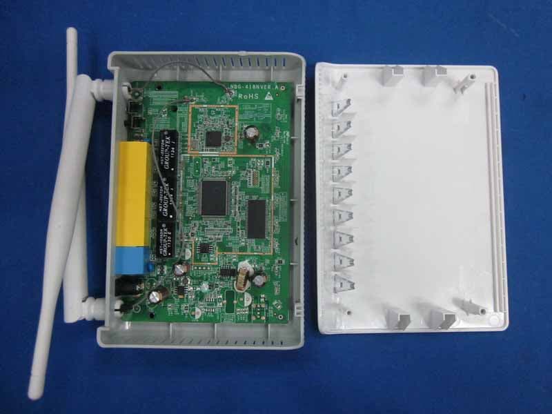
Click to zoom
Application Details
- Equipment Class
- DTS - Digital Transmission System
- Date of Grant
- May 28, 2012
- Application Purpose
- Original Equipment
- Date of Application
- May 26, 2012
- Equipment Note
- Wireless N Home Router Model No.: NBG-418N
- Frequency Range
- 2412.00000000 - 2462.00000000
- Country
- Taiwan
Documents & Files
Document Text
Text extracted from the exhibit documents filed with the FCC. Open a document above to read the original.
Users Manual
www.zyxel.com www.zyxel.com NBG-418N Wireless N Home Router IMPORTANT! READ CAREFULLY BEFORE USE. KEEP THIS GUIDE FOR FUTURE REFERENCE. IMPORTANT! Copyright © 2012 ZyXEL Communications Corporation Version 1.00 Edition 1, 4/2012 Default Login Details LAN IP Address http://192.168.1.1 User Nameadmin Password1234 NBG-418N User’s Guide2 IMPORTANT! READ CAREFULLY BEFORE USE. KEEP THIS GUIDE FOR FUTURE REFERENCE. Graphics in this book may differ slightly from the product due to differences in operating systems, operating system versions, or if you installed updated firmware/software for your device. Every effort has been made to ensure that the information in this manual is accurate. Related Documentation •Quick Start Guide The Quick Start Guide shows how to connect the NBG-418N and configure it using the Web Configurator wizard. Contents Overview NBG-418N User’s Guide 3 Contents Overview User’s Guide ....................................................................................................................................... 11 Introduction .............................................................................................................................................13 The Web Configurator .............................................................................................................................17 Connection Wizard ..................................................................................................................................21 Modes ....................................................................................................................................................35 Tutorials ..................................................................................................................................................57 Technical Reference .......................................................................................................................... 65 Wireless LAN ..........................................................................................................................................67 WAN ........................................................................................................................................................85 LAN .........................................................................................................................................................93 DHCP Server ..........................................................................................................................................97 Network Address Translation ................................................................................................................101 Dynamic DNS ........................................................................................................................................109 Firewall .................................................................................................................................................. 111 Remote Management ............................................................................................................................ 115 Universal Plug-and-Play (UPnP) ........................................................................................................... 119 System ..................................................................................................................................................125 Logs ......................................................................................................................................................129 Tools ......................................................................................................................................................131 Sys OP Mode ........................................................................................................................................137 Language ..............................................................................................................................................139 Troubleshooting ....................................................................................................................................141 Contents Overview NBG-418N User’s Guide 4 Table of Contents NBG-418N User’s Guide 5 Table of Contents Contents Overview .............................................................................................................................. 3 Table of Contents ................................................................................................................................. 5 Part I: User’s Guide ......................................................................................... 11 Chapter 1 Introduction ......................................................................................................................................... 13 1.1 Overview ...........................................................................................................................................13 1.2 Securing the NBG-418N ...................................................................................................................14 1.3 LEDs .................................................................................................................................................15 1.4 The WPS Button ...............................................................................................................................15 1.5 Wall Mounting ...................................................................................................................................16 Chapter 2 The Web Configurator ........................................................................................................................ 17 2.1 Overview ............................................................................................................................…
Text truncated - open the document above for the full version.
Users Manual
NBG-418N User’s Guide115 CHAPTER 13 Remote Management 13.1 Overview This chapter provides information on the Remote Management screens. Remote management allows you to determine which services/protocols can access which NBG- 418N interface (if any) from which computers. You may manage your NBG-418N from a remote location via: Note: When you configure remote management to allow management from the LAN and WAN in the options above, you still need to configure a firewall rule to allow access. See the firewall chapters for details on configuring firewall rules. •LAN only•LAN and WAN Chapter 13 Remote Management NBG-418N User’s Guide 116 13.1.1 Remote Management Limitations Remote management over LAN or WAN will not work when: 1You have disabled that service in one of the remote management screens. 2The IP address in the Secured Client WAN IP Address field does not match the client IP address. If it does not match, the NBG-418N will disconnect the session immediately. 3There is already another remote management session with an equal or higher priority running. You may only have one remote management session running at one time. 4There is a firewall rule that blocks it. 13.1.2 Remote Management and NAT When NAT is enabled: • Use the NBG-418N’s WAN IP address when configuring from the WAN. • Use the NBG-418N’s LAN IP address when configuring from the LAN. 13.1.3 System Timeout There is a default system management idle timeout of five minutes (three hundred seconds). The NBG-418N automatically logs you out if the management session remains idle for longer than this timeout period. The management session does not time out when a statistics screen is polling. You can change the timeout period in the System screen. 13.2 WWW Screen To change your NBG-418N’s World Wide Web settings, click Management > Remote MGMT to display the WWW screen. Figure 81 Management > Remote MGMT > WWW Chapter 13 Remote Management NBG-418N User’s Guide 117 The following table describes the labels in this screen. Table 51 Management > Remote MGMT > WWW LABELDESCRIPTION Server PortYou may change the server port number for a service if needed, however you must use the same port number in order to use that service for remote management. Server AccessSelect the interface(s) through which a computer may access the NBG-418N using this service. Secured Client WAN IP Address A secured client is a “trusted” computer that is allowed to communicate with the NBG-418N using this service. Select All to allow any computer to access the NBG-418N using this service. Choose Selected to just allow the computer with the IP address that you specify to access the NBG-418N using this service. Note: This only applies on WAN IP. ApplyClick Apply to save your customized settings and exit this screen. ResetClick Reset to begin configuring this screen afresh. Chapter 13 Remote Management NBG-418N User’s Guide 118 NBG-418N User’s Guide119 CHAPTER 14 Universal Plug-and-Play (UPnP) 14.1 Overview This chapter introduces the UPnP feature in the Web Configurator. Universal Plug and Play (UPnP) is a distributed, open networking standard that uses TCP/IP for simple peer-to-peer network connectivity between devices. A UPnP device can dynamically join a network, obtain an IP address, convey its capabilities and learn about other devices on the network. In turn, a device can leave a network smoothly and automatically when it is no longer in use. 14.2 What You Need to Know How do I know if I'm using UPnP? UPnP hardware is identified as an icon in the Network Connections folder (Windows XP). Each UPnP compatible device installed on your network will appear as a separate icon. Selecting the icon of a UPnP device will allow you to access the information and properties of that device. NAT Traversal UPnP NAT traversal automates the process of allowing an application to operate through NAT. UPnP network devices can automatically configure network addressing, announce their presence in the network to other UPnP devices and enable exchange of simple product and service descriptions. NAT traversal allows the following: • Dynamic port mapping • Learning public IP addresses • Assigning lease times to mappings Windows Messenger is an example of an application that supports NAT traversal and UPnP. See the NAT chapter for more information on NAT. Cautions with UPnP The automated nature of NAT traversal applications in establishing their own services and opening firewall ports may present network security issues. Network information and configuration may also be obtained and modified by users in some network environments. When a UPnP device joins a network, it announces its presence with a multicast message. For security reasons, the NBG-418N allows multicast messages on the LAN only. Chapter 14 Universal Plug-and-Play (UPnP) NBG-418N User’s Guide 120 All UPnP-enabled devices may communicate freely with each other without additional configuration. Disable UPnP if this is not your intention. 14.3 Configuring UPnP Use this screen to enable UPnP. Click the Management > UPnP to open the following screen. Figure 82 Management > UPnP > General The following table describes the labels in this screen. 14.3.1 Using UPnP in Windows XP Example This section shows you how to use the UPnP feature in Windows XP. You must already have UPnP installed in Windows XP and UPnP activated on the NBG-418N. Make sure the computer is connected to a LAN port of the NBG-418N. Turn on your computer and the NBG-418N. 14.3.1.1 Auto-discover Your UPnP-enabled Network Device 1Click start and Control Panel. Double-click Network Connections. An icon displays under Internet Gateway. Table 52 Management > UPnP > General LABELDESCRIPTION Enable the Universal Plug and Play (UPnP) Feature Select this check box to activate UPnP. Be aware that anyone could use a UPnP application to open the Web Configurator's login screen without entering the NBG-418N's IP address (although you must still enter the password to access t…
Text truncated - open the document above for the full version.
External Photos
R AUDIX Technology (Shenzhen) Co., Ltd. FCC ID:I88NBG418N page Audix Technology (Shenzhen) Co., Ltd. Report No. ACS-F12095 14-1 14. PHOTOS OF THE EUT Figure 1 General Appearance of the EUT Figure 2 General Appearance of the EUT R AUDIX Technology (Shenzhen) Co., Ltd. FCC ID:I88NBG418N page Audix Technology (Shenzhen) Co., Ltd. Report No. ACS-F12095 14-2 Figure 3 General Appearance of the EUT Figure 4 Inside of the EUT
ID Label/Location Info
NBG-418N I88NBG418N 0 铭牌 0 NBG-418N Wu fangqing 2012.03.20 Cheng hailing Mao zhigao 2012.03.20 2012.03.20 50#消银龙过哑胶 HQ170412031601 IP Address: 192.168.1.1(Router) Password: 1234 SSID: ZyXEL IP Address: 192.168.1.2( AP ) Password: 1234 SSID: ZyXEL Connect to broadband modem Connect to power adapter
Internal Photos
R AUDIX Technology (Shenzhen) Co., Ltd. FCC ID:I88NBG418N page Audix Technology (Shenzhen) Co., Ltd. Report No. ACS-F12095 14-2 Figure 3 General Appearance of the EUT Figure 4 Inside of the EUT R AUDIX Technology (Shenzhen) Co., Ltd. FCC ID:I88NBG418N page Audix Technology (Shenzhen) Co., Ltd. Report No. ACS-F12095 14-3 Figure 5 Inside of the EUT Figure 6 Components Side of the PCB R AUDIX Technology (Shenzhen) Co., Ltd. FCC ID:I88NBG418N page Audix Technology (Shenzhen) Co., Ltd. Report No. ACS-F12095 14-4 Figure 7 Components Side of the PCB Figure 8 Components Side of the PCB R AUDIX Technology (Shenzhen) Co., Ltd. FCC ID:I88NBG418N page Audix Technology (Shenzhen) Co., Ltd. Report No. ACS-F12095 14-5 Figure 9 Power Adapter Figure 10 Power Adapter
RF Exposure Info
R AUDIX Technology (Shenzhen) Co., Ltd. FCC ID:I88NBG418N page Audix Technology (Shenzhen) Co., Ltd. Report No. ACS-F12095 11-1 11. MPE ESTIMATION 11.1.Limit for General Population/ Uncontrolled Exposures Frequency Power density (mW/ cm 2 ) Averaging time(minutes) 300MHz----1.5GHz F/1500 30 1.5GHz---100GHz 1.0 30 Frequency(MHz) Power density (mW/ cm 2 ) Averaging time(minutes) 2412 1 30 2437 1 30 2462 1 30 Note: F= Frequency in MHz 11.2. Estimation Result EUT: Wireless N Home Router M/N: NBG-418N Test date: 2012-04-19 Pressure: 100.3 kpa Humidity: 52.9% Tested by: Leo-Li Test site: RF Site Temperature:25.4°C Cable loss: 1 dB Attenuator loss: 20 dB Antenna Gain: 5 dBi Test Mode CH Frequency (MHz) Peak Output Power (dBm) Output Power (mW) Antenna Gain (dBi) Antenna Gain (Linear) MPE CH1 2412 18.12 64.86 5 3.16 0.0408 CH6 2437 18.45 69.98 5 3.16 0.0441 11b CH11 2462 18.47 70.31 5 3.16 0.0443 CH1 2412 15.32 34.04 5 3.16 0.0214 CH6 2437 15.49 35.40 5 3.16 0.0223 11g CH11 2462 15.62 36.48 5 3.16 0.0230 CH1 2412 17.07 50.93 5 3.16 0.0321 CH6 2437 17.08 51.05 5 3.16 0.0321 11n HT20 CH11 2462 16.87 48.64 5 3.16 0.0306 CH1 2422 16.43 43.95 5 3.16 0.0277 CH4 2437 16.59 45.60 5 3.16 0.0287 11n HT40 CH7 2452 16.43 43.95 5 3.16 0.0277 Note: The estimation distance is 20cm
Test Report
R AUDIX Technology (Shenzhen) Co., Ltd. FCC ID:I88NBG418N page Audix Technology (Shenzhen) Co., Ltd. Report No. ACS-F12095 1-1 FCC PART 15C TEST REPORT FOR CERTIFICATION On Behalf of ZyXEL Communications Corporation Wireless N Home Router Model No.: NBG-418N FCC ID: I88NBG418N Prepared for : ZyXEL Communications Corporation No.6, Innovation Road II, Science Park, Hsinchu TAIWAN Prepared By : Audix Technology (Shenzhen) Co., Ltd. No. 6, Ke Feng Rd., 52 Block, Shenzhen Science & Industrial Park, Nantou, Shenzhen, Guangdong, China Tel: (0755) 26639496 Report Number Κ ACS-F12095 Date of Test Κ Apr.11~19, 2012 Date of Report Κ May.15, 2012 R AUDIX Technology (Shenzhen) Co., Ltd. FCC ID:I88NBG418N page Audix Technology (Shenzhen) Co., Ltd. Report No. ACS-F12095 1-2 TABLE OF CONTENTS Description Page 1.SUMMARY OF STANDARDS AND RESULTS ......................................................... 1-5 1.1.Description of Standards and Results...................................................................................1-5 2.GENERAL INFORMATION......................................................................................... 2-1 2.1.Description of Device (EUT) ...............................................................................................2-1 2.2.Test Information ...................................................................................................................2-2 2.3.Tested Supporting System Details .......................................................................................2-3 2.4.Block Diagram of Test Setup ...............................................................................................2-3 2.5.Test Facility..........................................................................................................................2-4 2.6.Measurement Uncertainty (95% confidence levels, k=2) ....................................................2-4 3.POWER LINE CONDUCTED EMISSION TEST ...................................................... 3-1 3.1.Test Equipments ...................................................................................................................3-1 3.2.Block Diagram of Test Setup ...............................................................................................3-1 3.3.Power Line Conducted Emission Test Limits ......................................................................3-1 3.4.Configuration of EUT on Test .............................................................................................3-2 3.5.Operating Condition of EUT................................................................................................3-2 3.6.Test Procedure......................................................................................................................3-2 3.7.Power Line Conducted Emission Test Results.....................................................................3-2 4.RADIATED EMISSION TEST...................................................................................... 4-1 4.1.Test Equipment ....................................................................................................................4-1 4.2.Block Diagram of Test Setup ...............................................................................................4-1 4.3.Radiated Emission Limit ......................................................................................................4-2 4.4.EUT Configuration on Test..................................................................................................4-3 4.5.Operating Condition of EUT................................................................................................4-3 4.6.Test Procedure......................................................................................................................4-3 4.7.Radiated Emission Test Results ...........................................................................................4-4 5.CONDUCTED SPURIOUS EMISSIONS ..................................................................... 5-1 5.1.Test Equipment ....................................................................................................................5-1 5.2.Limit .....................................................................................................................................5-1 5.3.Test Procedure......................................................................................................................5-1 5.4.Test result .............................................................................................................................5-1 6.BAND EDGE COMPLIANCE TEST............................................................................ 6-1 6.1.Test Equipment ....................................................................................................................6-1 6.2.Limit .....................................................................................................................................6-1 6.3.Test Produce .........................................................................................................................6-1 6.4.Test Results ..........................................................................................................................6-1 7.6dB Bandwidth Test ........................................................................................................ 7-1 7.1.Test Equipment ....................................................................................................................7-1 7.2.Limit .....................................................................................................................................7-1 7.3.Test Procedure......................................................................................................................7-1 7.4.Test Results .......................................................................................…
Text truncated - open the document above for the full version.
Test Setup Photos
R AUDIX Technology (Shenzhen) Co., Ltd. FCC ID:I88NBG418N page Audix Technology (Shenzhen) Co., Ltd. Report No. ACS-F12095 13-1 13. PHOTOGRAPH OF TEST 13.1.Photos of Power Line Conducted Emission Test R AUDIX Technology (Shenzhen) Co., Ltd. FCC ID:I88NBG418N page Audix Technology (Shenzhen) Co., Ltd. Report No. ACS-F12095 13-2 13.2.Photos of Radiated Emission Test R AUDIX Technology (Shenzhen) Co., Ltd. FCC ID:I88NBG418N page Audix Technology (Shenzhen) Co., Ltd. Report No. ACS-F12095 13-3 (Above 1000MHz)
Contact Information
Applicant
Emma Bao(Section Manager)
Technical Contact
AUDIX Technology (Shenzhen) Co., Ltd.
[email protected]86-755-26639497
52 Block Shenzhen Science&Industry · Shenzhen · China
Non-Technical Contact
AUDIX Technology (Shenzhen) Co., Ltd.
[email protected]86-755-26639497
Test Firm
Audix Technology (Shenzhen) Co., Ltd.Smart Tsai
Technical Specifications
| # | Rule Parts | Frequency Range | Power Output |
|---|---|---|---|
| 1 | 15C | 2.41 GHz - 2.46 GHz | 70.30 mW |
Other Applications from ZyXEL Communications Corporation
I88EE6601-00
Jul 18, 2024Tri-Band Wireless BE19000 10G Ethernet VoIP Gateway with SFP+ / Tri-Band Wireless BE19000 10G Ethernet VoIP Gateway / Tri-Band Wireless BE19000 10G Ethernet Gateway with SFP+ / Tri-Band Wireless BE19000 10G Ethernet Gateway
Equipment Class
6ID - 15E 6 GHz Low Power Indoor Access Point
I8803935
Oct 17, 2023802.11be (WiFi 7) Triple-Radio Unified Pro Access Point
Equipment Class
DTS - Digital Transmission System
I8803973
Aug 01, 2023802.11ax (WiFi 6) Dual-Radio Wall-Plate Unified Access Point
Equipment Class
NII - Unlicensed National Information Infrastructure TX
I88WX5610-B0
Apr 25, 2023AX7800 WiFi 6E Tri-Band Gigabit Wireless Extender
Equipment Class
DTS - Digital Transmission System
I88EX7710-B0
Apr 16, 2023AX11000 WiFi 6E 10G Ethernet Gateway
Equipment Class
NII - Unlicensed National Information Infrastructure TX