I88NBG6515AC750 Dual band Wireless Gigabit Router
ZyXEL Communications Corporation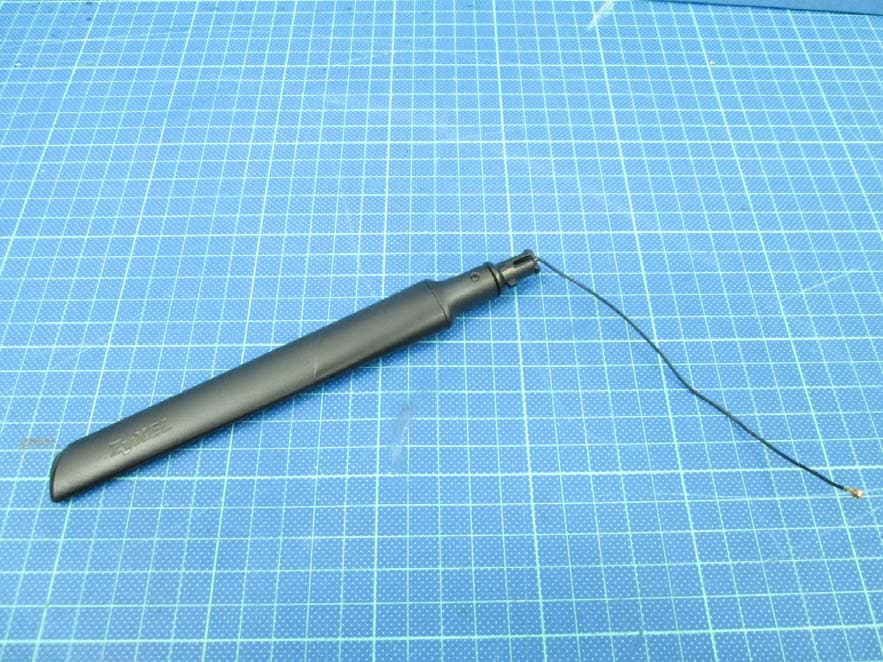
Click to zoom
Application Details
- Equipment Class
- NII - Unlicensed National Information Infrastructure TX
- Date of Grant
- Jul 27, 2015
- Application Purpose
- Original Equipment
- Date of Application
- Jul 27, 2015
- Equipment Note
- AC750 Dual band Wireless Gigabit Router
- Frequency Range
- 5745.00000000 - 5825.00000000
- Country
- Taiwan
Documents & Files
Document Text
Text extracted from the exhibit documents filed with the FCC. Open a document above to read the original.
Users Manual
Quick Start Guide www.zyxel.com NBG6515 AC750 Dual-Band Wireless Gigabit Router Version 1.00 Edition 1, 05/2015 User’s Guide Default Details LAN IP Address - Router Mode (Default mode) http://192.168.1.1 - AP/Repeater Mode http://192.168.1.2 User Nameadmin Password1234 2.4G SSIDZyXEL + Last 6 digits of the 2.4G MAC address (ZyXEL734916) 5G SSIDZyXEL+ Last 6 digits of the 5G MAC address + .speed (ZyXEL734917.speed) Pre-shared KeySerial number + Random key Copyright © 2015 ZyXEL Communications Corporation NBG6515 User’s Guide 2 IMPORTANT! READ CAREFULLY BEFORE USE. KEEP THIS GUIDE FOR FUTURE REFERENCE. Screenshots and graphics in this book may differ slightly from your product due to differences in your product firmware or your computer operating system. Every effort has been made to ensure that the information in this manual is accurate. Related Documentation •Quick Start Guide The Quick Start Guide shows how to connect the NBG and access the Web Configurator. Note: It is recommended you use the Web Configurator to configure the NBG. Contents Overview NBG6515 User’s Guide 3 Contents Overview User’s Guide ....................................................................................................................................... 11 Getting to Know Your NBG .....................................................................................................................12 Connection Wizard ..................................................................................................................................17 Introducing the Web Configurator ...........................................................................................................26 Monitor ....................................................................................................................................................31 NBG Modes .............................................................................................................................................36 Easy Mode ..............................................................................................................................................38 Router Mode ...........................................................................................................................................50 Access Point Mode .................................................................................................................................57 Universal Repeater Mode .......................................................................................................................63 Tutorials ..................................................................................................................................................72 Technical Reference .......................................................................................................................... 79 Wireless LAN ..........................................................................................................................................80 IPv6 .........................................................................................................................................................96 WAN ......................................................................................................................................................101 LAN ....................................................................................................................................................... 111 DHCP Server ........................................................................................................................................ 114 Network Address Translation (NAT) ...................................................................................................... 117 Dynamic DNS ........................................................................................................................................123 Static Route ...........................................................................................................................................125 Firewall ..................................................................................................................................................127 Content Filter .........................................................................................................................................134 Bandwidth Management .......................................................................................................................136 Remote Management ............................................................................................................................142 Universal Plug-and-Play (UPnP) ...........................................................................................................144 USB Media Sharing ...............................................................................................................................151 Maintenance ..........................................................................................................................................160 Troubleshooting ....................................................................................................................................167 Table of Contents NBG6515 User’s Guide 4 Table of Contents Contents Overview .............................................................................................................................. 3 Table of Contents ................................................................................................................................. 4 Part I: User’s Guide ......................................................................................... 11 Chapter 1 Getting to Know Your NBG ................................................................................................................ 12 1.1 Overview .......…
Text truncated - open the document above for the full version.
Users Manual
NBG6515 User’s Guide 174 APPENDIX A IP Addresses and Subnetting This appendix introduces IP addresses and subnet masks. IP addresses identify individual devices on a network. Every networking device (including computers, servers, routers, printers, etc.) needs an IP address to communicate across the network. These networking devices are also known as hosts. Subnet masks determine the maximum number of possible hosts on a network. You can also use subnet masks to divide one network into multiple sub-networks. Introduction to IP Addresses One part of the IP address is the network number, and the other part is the host ID. In the same way that houses on a street share a common street name, the hosts on a network share a common network number. Similarly, as each house has its own house number, each host on the network has its own unique identifying number - the host ID. Routers use the network number to send packets to the correct network, while the host ID determines to which host on the network the packets are delivered. Structure An IP address is made up of four parts, written in dotted decimal notation (for example, 192.168.1.1). Each of these four parts is known as an octet. An octet is an eight-digit binary number (for example 11000000, which is 192 in decimal notation). Therefore, each octet has a possible range of 00000000 to 11111111 in binary, or 0 to 255 in decimal. The following figure shows an example IP address in which the first three octets (192.168.1) are the network number, and the fourth octet (16) is the host ID. Appendix A IP Addresses and Subnetting NBG6515 User’s Guide 175 Figure 130 Network Number and Host ID How much of the IP address is the network number and how much is the host ID varies according to the subnet mask. Subnet Masks A subnet mask is used to determine which bits are part of the network number, and which bits are part of the host ID (using a logical AND operation). The term “subnet” is short for “sub-network”. A subnet mask has 32 bits. If a bit in the subnet mask is a “1” then the corresponding bit in the IP address is part of the network number. If a bit in the subnet mask is “0” then the corresponding bit in the IP address is part of the host ID. The following example shows a subnet mask identifying the network number (in bold text) and host ID of an IP address (192.168.1.2 in decimal). By convention, subnet masks always consist of a continuous sequence of ones beginning from the leftmost bit of the mask, followed by a continuous sequence of zeros, for a total number of 32 bits. Subnet masks can be referred to by the size of the network number part (the bits with a “1” value). For example, an “8-bit mask” means that the first 8 bits of the mask are ones and the remaining 24 bits are zeroes. Table 81 IP Address Network Number and Host ID Example 1ST OCTET: (192) 2ND OCTET: (168) 3RD OCTET: (1) 4TH OCTET (2) IP Address (Binary)11000000101010000000000100000010 Subnet Mask (Binary)11111111111111111111111100000000 Network Number110000001010100000000001 Host ID00000010 Appendix A IP Addresses and Subnetting NBG6515 User’s Guide 176 Subnet masks are expressed in dotted decimal notation just like IP addresses. The following examples show the binary and decimal notation for 8-bit, 16-bit, 24-bit and 29-bit subnet masks. Network Size The size of the network number determines the maximum number of possible hosts you can have on your network. The larger the number of network number bits, the smaller the number of remaining host ID bits. An IP address with host IDs of all zeros is the IP address of the network (192.168.1.0 with a 24-bit subnet mask, for example). An IP address with host IDs of all ones is the broadcast address for that network (192.168.1.255 with a 24-bit subnet mask, for example). As these two IP addresses cannot be used for individual hosts, calculate the maximum number of possible hosts in a network as follows: Notation Since the mask is always a continuous number of ones beginning from the left, followed by a continuous number of zeros for the remainder of the 32 bit mask, you can simply specify the number of ones instead of writing the value of each octet. This is usually specified by writing a “/” followed by the number of bits in the mask after the address. For example, 192.1.1.0 /25 is equivalent to saying 192.1.1.0 with subnet mask 255.255.255.128. The following table shows some possible subnet masks using both notations. Table 82 Subnet Masks BINARY DECIMAL 1ST OCTET 2ND OCTET 3RD OCTET 4TH OCTET 8-bit mask11111111000000000000000000000000255.0.0.0 16-bit mask11111111111111110000000000000000255.255.0.0 24-bit mask11111111111111111111111100000000255.255.255.0 29-bit mask11111111111111111111111111111000255.255.255.248 Table 83 Maximum Host Numbers SUBNET MASKHOST ID SIZE MAXIMUM NUMBER OF HOSTS 8 bits255.0.0.024 bits2 24 – 216777214 16 bits255.255.0.016 bits2 16 – 265534 24 bits255.255.255.08 bits2 8 – 2254 29 bits255.255.255.2483 bits2 3 – 26 Table 84 Alternative Subnet Mask Notation SUBNET MASK ALTERNATIVE NOTATION LAST OCTET (BINARY) LAST OCTET (DECIMAL) 255.255.255.0/240000 00000 255.255.255.128/251000 0000128 255.255.255.192/261100 0000192 Appendix A IP Addresses and Subnetting NBG6515 User’s Guide 177 Subnetting You can use subnetting to divide one network into multiple sub-networks. In the following example a network administrator creates two sub-networks to isolate a group of servers from the rest of the company network for security reasons. In this example, the company network address is 192.168.1.0. The first three octets of the address (192.168.1) are the network number, and the remaining octet is the host ID, allowing a maximum of 2 8 – 2 or 254 possible hosts. The following figure shows the company network before subnetting. Figure 131 Subnetting Example: Before Subnetting You can “borrow” one of the host ID bits to divide the network 192.168.1.0 into two separate sub- networks. The subnet mask is now 25 bits (255.255.255.128…
Text truncated - open the document above for the full version.
Cover Letter(s)
ZyXEL Communications Corporation No.2, Gongye E. 9 th Road, Hsinchu Science Park, Hsinchu, Taiwan Date: April 20, 2015 Subject: Ad Hoc Mode Function Declaration FCC ID: I88NBG6515 To whom it may concern, This device is acting as master and operating on 2.4GHz band. Ad Hoc function is available on client mode and not able to work on non-US frequencies. Please contact the one signed below or the authorized agent for this filing. Thank you. Regards, Signature FCC grantee contact person information. Name/Title: Emma Bao / Section Manager Company Name: ZyXEL Communications Corporation Address: No.2, Gongye E. 9 th Road, Hsinchu Science Park, Hsinchu, Taiwan TEL: 886-3-5783942 #88582 FAX: 886-3-5798870 Email: [email protected]
External Photos
External photo of EUT External photo of EUT I/O interfaces 2.4G Chain 0 + 5G Antenna 1 External photo of EUT 2.4G Chain 0 + 5G Antenna 2 2.4G Chain 1 Antenna 1 External photo of EUT 2.4G Chain 1 Antenna 2 External photo of EUT
ID Label/Location Info
Label Location
Internal Photos
Internal photo of EUT Internal photo of EUT Internal photo of EUT RF Module 1 Internal photo of EUT RF Module 2 RF Module 2 Internal photo of EUT Antenna 1 Antenna 2 2.4G chain 1 5G 2.4G chain 0 2.4G chain 1 5G 2.4G chain 0
RF Exposure Info
FCC ID: I88NBG6515 Report No.: 150400022TWN-001 Page 1 of 14 0597 Maximum Permissible Exposure (MPE) Evaluation Report Report No. : 150400022TWN-001 Model No. : NBG6515 Issued Date : Jun. 17, 2015 Applicant: ZyXEL Communications Corporation No.2, Gongye E. 9th Road, Hsinchu Science Park, Hsinchu, Taiwan Test Method/ Standard: FCC 1.1310 Test By: Intertek Testing Services Taiwan Ltd. No. 11, Lane 275, Ko-Nan 1 Street, Chia-Tung Li, Shiang-Shan District, Hsinchu City, Taiwan It may be duplicated completely for legal use with the allowance of the applicant. It shall not be reproduced except in full, without the written approval of Intertek Laboratory. The test result(s) in this report only applies to the tested sample(s). The test report was prepared by: Candy Liu/ Assistant These measurements were taken by: Ricky Lee/ Engineer The test report was reviewed by: Name Jimmy Yang Title Senior Engineer FCC ID: I88NBG6515 Report No.: 150400022TWN-001 Page 2 of 14 Revision History Report No. Issue Date Revision Summary 150400022TWN-001Jun. 17, 2015 Original report FCC ID: I88NBG6515 Report No.: 150400022TWN-001 Page 3 of 14 Table of Contents Summary of Tests ..............................................................................................................4 1. General information ......................................................................................................5 1.1 Identification of the EUT ........................................................................................5 1.2 Adapter information ................................................................................................6 1.3 Additional information about the EUT....................................................................6 1.4 Peripherals equipment .............................................................................................7 1.5 Antenna description.................................................................................................7 2. Test specifications .........................................................................................................8 2.1 Introduction .............................................................................................................8 2.2 RF Exposure Limit ..................................................................................................9 2.3 RF Exposure calculations......................................................................................11 2.4 Operation mode .....................................................................................................11 2.5 Test equipment ......................................................................................................12 2.6 Test Set-up .............................................................................................................12 3. Test results ...................................................................................................................13 FCC ID: I88NBG6515 Report No.: 150400022TWN-001 Page 4 of 14 Summary of Tests MPE Evaluation meet FCC OET No. 65: 1997, IEEE C95.1-2005 Test Reference Results MPE Evaluation FCC Guidelines for Human Exposure IEEE C95.1Complies FCC ID: I88NBG6515 Report No.: 150400022TWN-001 Page 5 of 14 1. General information 1.1 Identification of the EUT Product: AC750 Dual-Band Wireless Gigabit Router Model No: NBG6515 FCC ID: I88NBG6515 Manufacturer: ZyXEL Communications Corporation Address: No.2, Gongye E. 9th Road, Hsinchu Science Park, Hsinchu, Taiwan Frequency Range: 1. 2412 MHz ~ 2462 MHz for 802.11b, 802.11g, 802.11n HT20 2. 2422 MHz ~ 2452 MHz for 802.11n HT40 3. 5180 MHz ~ 5240 MHz for 802.11a, 802.11n(HT20), 802.11ac(VHT20) 4. 5190 MHz ~ 5230 MHz for 802.11n (HT40) , 802.11ac(VHT40) 5. 5745 MHz ~ 5825 MHz for 802.11a, 802.11n (HT20) , 802.11ac(VHT20) 6. 5755 MHz ~ 5795 MHz for 802.11n (HT40) 802.11ac(VHT40) 7. 5210 MHz, 5775 MHz for 802.11ac (VHT80) Channel Number: 1. 11 channels for 2412 MHz ~ 2462 MHz 2. 7 channels for 2422 MHz ~ 2452 MHz 3. 4 channels for 5180 MHz ~ 5240 MHz for 802.11a, 802.11n (HT20), 802.11ac(VHT20) 4. 2 channels for 5190 MHz ~ 5230 MHz for 802.11n (HT40), 802.11ac(VHT40) 5. 5 channels for 5745 MHz ~ 5825 MHz for 802.11a, 802.11n (HT20), 802.11ac(VHT20) 6. 2 channels for 5755 MHz ~ 5795 MHz for 802.11n (HT40) , 802.11ac(VHT40) 7. 1 channels for 5210 MHz, 5775 MHz for 802.11ac (VHT80) Type of Modulation: DSSS, OFDM Rated Power: DC 12 V from adapter Power Cord: N/A Sample Received: Mar. 23, 2015 Test Date(s): Apr. 02, 2015 ~ Jun.16, 2015 Note 1: This report is for the exclusive use of Intertek's Client and is provided pursuant to the agreement between Intertek and its Client. Intertek's responsibility and liability are limited to the terms and conditions of the agreement. Intertek assumes no liability to any party, other than to the Client in accordance with the agreement, for any loss, expense or damage occasioned by the use of this report. Only the Client is authorized to permit copying or distribution of this report and then only in its entirety. Any use of the Intertek name or one of its marks for the sale or advertisement of the tested material, product or service must first be approved in writing by Intertek. The observations and test results in this report are relevant only to the sample tested. This report by itself does not imply that the material, product, or service is or has ever been under an Intertek certification program. Note 2: When determining the test conclusion, the Measurement Uncertainty of test has been considered. FCC ID: I88NBG6515 Report No.: 150400022TWN-001 Page 6 of 14 1.2 Adapter information The EUT will be supplied with a power supply from below list No. Brand Model no. Specification Adapter APD WA-12M12FU I/P: 100-240Vac, 50-60Hz, 0.5A O/P: 12Vdc, 1A 1.3 Additional information about the EUT For 2.4 GHz Transmit path Modulation mode Chain 0 / Main Chain 1 / AUX 802.11b V X 802.11g V X 802.11 n…
Text truncated - open the document above for the full version.
Test Report
FCC ID: I88NBG6515 Report No.: 150400018TWN-001 Page 1 of 61 EMC TEST REPORT Applicant: ZyXEL Communications Corporation No.2, Gongye E. 9th Road, Hsinchu Science Park, Hsinchu, Taiwan Test Method/ Standard: 47 CFR FCC Part 15.407 KDB 789033 D02 v01 KDB 644545 D03 v01 ANSI C63.10 2013. Test By: Intertek Testing Services Taiwan Ltd. No. 11, Lane 275, Ko-Nan 1 Street, Chia-Tung Li, Shiang-Shan District, Hsinchu City, Taiwan It may be duplicated completely for legal use with the allowance of the applicant. It shall not be reproduced except in full, without the written approval of Intertek Laboratory. The test result(s) in this report only applies to the tested sample(s). The test report was prepared by: Candy Liu/ Assistant These measurements were taken by: Ricky Lee / Engineer The test report was reviewed by: Name Jimmy Yang Title Senior Engineer Report No. : 150400018TWN-001 Model No. : NBG6515 Issued Date : Jun. 17, 2015 FCC ID: I88NBG6515 Report No.: 150400018TWN-001 Page 2 of 61 Revision History Report No. Issue Date Revision Summary 150400018TWN-001Jun. 17, 2015 Original report FCC ID: I88NBG6515 Report No.: 150400018TWN-001 Page 3 of 61 Table of Contents 1. Summary of Test Data ........................................................................................................... 5 2. General information .............................................................................................................. 6 2.1 Identification of the EUT ................................................................................................ 6 2.2 Description of EUT .........................................................................................................7 2.3 Additional information of EUT ....................................................................................... 7 2.4 Antenna description.........................................................................................................7 2.5 Adapter information ........................................................................................................7 2.6 Peripherals equipment ..................................................................................................... 8 2.7 Operation mode ............................................................................................................... 8 2.8 Applied test modes and channels .................................................................................... 9 2.9 Power setting of test software ....................................................................................... 10 3. Maximum Conducted Output Power................................................................................... 13 3.1 Operating environment.................................................................................................. 13 3.2 Limit for maximum output power ................................................................................. 13 3.3 Measuring instrument setting ........................................................................................ 13 3.4 Test procedure ............................................................................................................... 14 3.5 Test diagram .................................................................................................................. 14 3.6 Test results ..................................................................................................................... 14 4. Power Spectrum Density ..................................................................................................... 16 4.1 Operating environment.................................................................................................. 16 4.2 Limit for power spectrum density ................................................................................. 16 4.3 Measuring instrument setting ........................................................................................ 16 4.4 Test procedure ............................................................................................................... 17 4.5 Test diagram .................................................................................................................. 17 4.6 Test results ..................................................................................................................... 18 5. Minimum Bandwidth .......................................................................................................... 28 5.1 Operating environment.................................................................................................. 28 5.2 Limit for minimum emission bandwidth....................................................................... 28 5.3 Measuring instrument setting ........................................................................................ 28 5.4 Test procedure ............................................................................................................... 29 5.5 Test diagram .................................................................................................................. 29 5.6 Test results ..................................................................................................................... 29 6. Emissions in Restricted Frequency Bands (Radiated emission measurements) ................. 44 6.1 Operating environment.................................................................................................. 44 6.2 Limit for emission in restricted frequency bands (Radiated emission measurement) .. 44 6.3 Measuring instrument setting ........................................................................................ 45 6.4 Test procedure ............................................................................................................... 46 6.5 Test configuration......................................................................................…
Text truncated - open the document above for the full version.
Test Setup Photos
Conducted Emission Test set-up photo
Test Setup Photos
Radiated Emission Test set-up photo Radiated Emission Test set-up photo
Contact Information
Applicant
Emma Bao(Section Manager)
Test Firm
Intertek Testing Services Taiwan Ltd.Alpha Liu
Technical Specifications
| # | Rule Parts | Frequency Range | Power Output |
|---|---|---|---|
| 2 | 15E | 5.75 GHz - 5.83 GHz | 545.00 mW |
Other Applications from ZyXEL Communications Corporation
I88EE6601-00
Jul 18, 2024Tri-Band Wireless BE19000 10G Ethernet VoIP Gateway with SFP+ / Tri-Band Wireless BE19000 10G Ethernet VoIP Gateway / Tri-Band Wireless BE19000 10G Ethernet Gateway with SFP+ / Tri-Band Wireless BE19000 10G Ethernet Gateway
Equipment Class
6ID - 15E 6 GHz Low Power Indoor Access Point
I8803935
Oct 17, 2023802.11be (WiFi 7) Triple-Radio Unified Pro Access Point
Equipment Class
DTS - Digital Transmission System
I8803973
Aug 01, 2023802.11ax (WiFi 6) Dual-Radio Wall-Plate Unified Access Point
Equipment Class
NII - Unlicensed National Information Infrastructure TX
I88WX5610-B0
Apr 25, 2023AX7800 WiFi 6E Tri-Band Gigabit Wireless Extender
Equipment Class
DTS - Digital Transmission System
I88EX7710-B0
Apr 16, 2023AX11000 WiFi 6E 10G Ethernet Gateway
Equipment Class
NII - Unlicensed National Information Infrastructure TX