I88NVG2053Wireless N Gigabit VoIP Gateway
ZyXEL Communications Corporation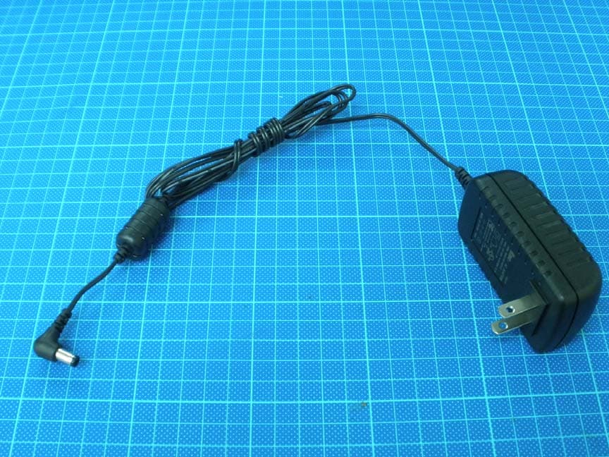
Click to zoom
Application Details
- Equipment Class
- DTS - Digital Transmission System
- Date of Grant
- Mar 30, 2011
- Application Purpose
- Original Equipment
- Date of Application
- Mar 28, 2011
- Equipment Note
- Wireless N Gigabit VoIP Gateway
- Frequency Range
- 2422.00000000 - 2452.00000000
- Country
- Taiwan
Documents & Files
Document Text
Text extracted from the exhibit documents filed with the FCC. Open a document above to read the original.
Users Manual
www.zyxel.com www.zyxel.com NVG2053 Wireless N Gigabit VoIP Gateway Copyright © 2011 ZyXEL Communications Corporation Firmware Version 1.0 Edition 1, 02/2011 Default Login Details IP Addresshttp://192.168.1.1 Password1234 About This User's Guide NVG2053 User’s Guide 3 About This User's Guide Intended Audience This manual is intended for people who want to configure the NVG2053 using the Web Configurator. Related Documentation •Quick Start Guide The Quick Start Guide is designed to help you get up and running right away. It contains information on setting up your network and configuring for Internet access. • Support Disc Refer to the included CD for support documents. Documentation Feedback Send your comments, questions or suggestions to: [email protected] Thank you! The Technical Writing Team, ZyXEL Communications Corp., 6 Innovation Road II, Science-Based Industrial Park, Hsinchu, 30099, Taiwan. Need More Help? More help is available at www.zyxel.com. • Download Library Search for the latest product updates and documentation from this link. Read the Tech Doc Overview to find out how to efficiently use the documentation in order to better understand how to use your product. About This User's Guide NVG2053 User’s Guide 4 • Knowledge Base If you have a specific question about your product, the answer may be here. This is a collection of answers to previously asked questions about ZyXEL products. •Forum This contains discussions on ZyXEL products. Learn from others who use ZyXEL products and share your experiences as well. Customer Support Should problems arise that cannot be solved by the methods listed above, you should contact your vendor. If you cannot contact your vendor, then contact a ZyXEL office for the region in which you bought the device. See http://www.zyxel.com/web/contact_us.php for contact information. Please have the following information ready when you contact an office. • Product model and serial number. •Warranty Information. • Date that you received your device. • Brief description of the problem and the steps you took to solve it. Document Conventions NVG2053 User’s Guide 5 Document Conventions Warnings and Notes These are how warnings and notes are shown in this User’s Guide. Warnings tell you about things that could harm you or your device. Note: Notes tell you other important information (for example, other things you may need to configure or helpful tips) or recommendations. Syntax Conventions • The NVG2053 may be referred to as the “NVG2053”, the “device”, the “product” or the “system” in this User’s Guide. • Product labels, screen names, field labels and field choices are all in bold font. • A key stroke is denoted by square brackets and uppercase text, for example, [ENTER] means the “enter” or “return” key on your keyboard. • “Enter” means for you to type one or more characters and then press the [ENTER] key. “Select” or “choose” means for you to use one of the predefined choices. • A right angle bracket ( > ) within a screen name denotes a mouse click. For example, Maintenance > Log > Log Setting means you first click Maintenance in the navigation panel, then the Log sub menu and finally the Log Setting tab to get to that screen. • Units of measurement may denote the “metric” value or the “scientific” value. For example, “k” for kilo may denote “1000” or “1024”, “M” for mega may denote “1000000” or “1048576” and so on. • “e.g.,” is a shorthand for “for instance”, and “i.e.,” means “that is” or “in other words”. Icons Used in Figures Figures in this User’s Guide use the following generic icons. The NVG2053 icon is not an exact representation of your NVG2053. Graphics in this book may differ slightly from the product due to differences in operating systems, operating system versions, or if you installed updated Document Conventions NVG2053 User’s Guide 6 firmware/software for your device. Every effort has been made to ensure that the information in this manual is accurate. NVG2053ComputerNotebook computer ServerModemFirewall Te l e p h o n eSwitchRouter Safety Warnings NVG2053 User’s Guide 7 Safety Warnings • Do NOT use this product near water, for example, in a wet basement or near a swimming pool. • Do NOT expose your device to dampness, dust or corrosive liquids. • Do NOT store things on the device. • Do NOT install, use, or service this device during a thunderstorm. There is a remote risk of electric shock from lightning. • Connect ONLY suitable accessories to the device. • Do NOT open the device or unit. Opening or removing covers can expose you to dangerous high voltage points or other risks. ONLY qualified service personnel should service or disassemble this device. Please contact your vendor for further information. • Make sure to connect the cables to the correct ports. • Place connecting cables carefully so that no one will step on them or stumble over them. • Always disconnect all cables from this device before servicing or disassembling. • Use ONLY an appropriate power adaptor or cord for your device. • Connect the power adaptor or cord to the right supply voltage (for example, 110V AC in North America or 230V AC in Europe). • Do NOT allow anything to rest on the power adaptor or cord and do NOT place the product where anyone can walk on the power adaptor or cord. • Do NOT use the device if the power adaptor or cord is damaged as it might cause electrocution. • If the power adaptor or cord is damaged, remove it from the power outlet. • Do NOT attempt to repair the power adaptor or cord. Contact your local vendor to order a new one. • Do not use the device outside, and make sure all the connections are indoors. There is a remote risk of electric shock from lightning. • Do NOT obstruct the device ventilation slots, as insufficient airflow may harm your device. • Antenna Warning! This device meets ETSI and FCC certification requirements when using the included antenna(s). Only use the included antenna(s). • If you wall mount your device, make sur…
Text truncated - open the document above for the full version.
Users Manual
NVG2053 User’s Guide 201 CHAPTER19 Management 19.1 Overview This chapter explains how to configure TR-069 and remote management on the NVG2053. 19.1.1 What You Can Do in this Chapter •Use the TR-069 screen (Section 19.5 on page 204) to configure the NVG2053’s TR-069 auto-configuration settings. •Use the WWW screen (Section 19.5 on page 204) to configure the NVG2053’s HTTP management settings. •Use the Telnet screen (Section 19.5 on page 204) to specify which interfaces allow Telnet access and from which IP address the access can come. •Use the ICMP screen (Section 19.6 on page 205) to specify which of the NVG2053’s interfaces will respond to Ping requests. 19.2 What You Need To Know Firewall Rules When you configure remote management to allow management from any network except the LAN, you still need to configure a firewall rule to allow access. See Chapter 13 on page 251 for details on configuring firewall rules. You can also disable a service on the NVG2053 by not allowing access for the service/protocol through any of the NVG2053 interfaces. Remote Management Sessions You may only have one remote management session running at a time. The NVG2053 automatically disconnects a remote management session of lower priority when another remote management session of higher priority starts. The priorities for the different types of remote management sessions are as follows. Chapter 19 Management NVG2053 User’s Guide 202 1Tel net 2HTTP Remote Management Limitations Remote management does not work when: 1You have not enabled that service on the interface in the corresponding remote management screen. 2You have disabled that service in one of the remote management screens. 3The IP address in the Secured Client IP Address field does not match the client IP address. If it does not match, the NVG2053 will disconnect the session immediately. 4There is already another remote management session with an equal or higher priority running. You may only have one remote management session running at one time. 5There is a firewall rule that blocks it. System Timeout There is a default system management idle timeout of five minutes (three hundred seconds). The NVG2053 automatically logs you out if the management session remains idle for longer than this timeout period. The management session does not time out when a statistics screen is polling. You can change the timeout period in the Maintenance > Generalscreen. 19.3 The TR-069 Screen TR-069 defines how Customer Premise Equipment (CPE), for example your NVG2053, can be managed over the WAN by an Auto Configuration Server (ACS). TR-069 is based on sending Remote Procedure Calls (RPCs) between an ACS and a client device. RPCs are sent in Extensible Markup Language (XML) format over HTTP or HTTPS. An administrator can use an ACS to remotely set up the NVG2053, modify settings, perform firmware upgrades as well as monitor and diagnose the NVG2053. You have to enable the device to be managed by the ACS and specify the ACS IP address or domain name and username and password. Chapter 19 Management NVG2053 User’s Guide 203 ClickConfiguration > Management > TR-069 to open the following screen. Use this screen to configure your NVG2053 to be managed by an ACS. Figure 87 Management > TR-069 The following table describes the fields in this screen. Table 69 Management > TR-069 LABELDESCRIPTION TR069Select Enableto activate remote management via TR-069 on the WAN. Otherwise, select Disable. ACS URLEnter the URL or IP address of the auto-configuration server. ACS UsernameEnter the TR-069 user name for authentication with the auto- configuration server. ACS PasswordEnter the TR-069 password for authentication with the auto- configuration server. Connection Request Username Enter the connection request user name. When the ACS makes a connection request to the NVG2053, this user name is used to authenticate the ACS. Connection Request Password Enter the connection request password. When the ACS makes a connection request to the NVG2053, this password is used to authenticate the ACS. Periodic Inform Interval The NVG2053 can initiate a connection to the ACS using the pre- configured address at any time. Enter the time interval (in seconds) at which the NVG2053 sends information to the auto-configuration server. “0” means the NVG2053 will not establish periodic communication with the ACS. ApplyClickApply to save your changes back to the NVG2053. CancelClickCancel to begin configuring this screen afresh. Chapter 19 Management NVG2053 User’s Guide 204 19.4 The WWW Screen Use this screen to configure the NVG2053’s HTTP management settings. Note: If you disable the HTTP service in the WWWscreen, then the NVG2053 blocks all HTTP connection attempts. ClickManagement > Remote MGMT > WWW to open the following screen. Figure 88 Remote MGMT > WWW The following table describes the fields in this screen. 19.5 The Telnet Screen Use this screen to specify which interfaces allow Telnet access and from which IP address the access can come. Table 70 Remote MGMT > WWW LABELDESCRIPTION PortYou may change the server port number for a service if needed, however you must use the same port number in order to use that service for remote management. Access StatusSelect the interface(s) through which a computer may access the NVG2053 using this service. Secured Client IP Address A secure client is a “trusted” computer that is allowed to communicate with the NVG2053 using this service. Select All to allow any computer to access the NVG2053 using this service. Choose Selected to just allow the computer with the IP address that you specify to access the NVG2053 using this service. Apply Click this to save your changes and to apply them to the NVG2053. Cancel Click this to set every field in this screen to its last-saved value. Chapter 19 Management NVG2053 User’s Guide 205 ClickManagement > Remote MGMT > Telnet to open the following screen. Figure 89 Remote MGMT > Telnet The following table describes the fie…
Text truncated - open the document above for the full version.
External Photos
External photo of EUT Antenna 1 Antenna 2 External photo of EUT Antenna Antenna External photo of EUT Antenna Connect External photo of EUT Adapter: SYS1308-2412-W2 Adapter: SYS1308-2412-W2 External photo of EUT Adapter: KSAD1200150W1US Adapter: KSAD1200150W1US
ID Label/Location Info
FCC ID Label Location
Internal Photos
Internal photo of EUT Internal photo of EUT Internal photo of EUT
RF Exposure Info
FCC ID. : I88NVG2053 Report No.: TS11020088-EME Page 1 of 8 Maximum Permissible Exposure (MPE) Evaluation Report Report No. : TS11020088-EME Model No. : NVG2053 Issued Date : Mar. 11, 2011 Applicant: ZyXEL Communications Corporation No. 6, Innovation Rd II, Science-Based Industrial Park, Hsin-Chu, Taiwan Test Method/ Standard: FCC 1.1310 Test By: Intertek Testing Services Taiwan Ltd. No. 11, Lane 275, Ko-Nan 1 Street, Chia-Tung Li, Shiang-Shan District, Hsinchu City, Taiwan It may be duplicated completely for legal use with the allowance of the applicant. It shall not be reproduced except in full, without the written approval of Intertek Laboratory. The test result(s) in this report only applies to the tested sample(s). The test report was prepared by: Sign on File Jill Chen / Assistant These measurements were taken by: Sign on File Terry Hsu / Engineer The test report was reviewed by: Name Jimmy Yang Title Engineer FCC ID. : I88NVG2053 Report No.: TS11020088-EME Page 2 of 8 Table of Contents Summary of Tests ............................................................................................................. 3 1. Introduction .................................................................................................................. 4 2. RF Exposure Limit ....................................................................................................... 4 3. RF Exposure calculations ............................................................................................. 5 4 Description of EUT ....................................................................................................... 6 5. Test results .................................................................................................................... 7 6. Set-up Photo .................................................................................................................8 FCC ID. : I88NVG2053 Report No.: TS11020088-EME Page 3 of 8 Summary of Tests MPE Evaluation meet FCC OET No. 65: 1997, IEEE C95.1-2005 Wireless N Gigabit VoIP Gateway -Model: NVG2053 FCC ID: I88NVG2053 Test Reference Results MPE Evaluation FCC Guidelines for Human Exposure IEEE C95.1 Complies FCC ID. : I88NVG2053 Report No.: TS11020088-EME Page 4 of 8 1. Introduction The EUT operates in the 2.4 GHz ISM band. Due to the EUT (include antenna) at its normal operation distance is at least 20 cm from the human body, the EUT was defined as a Mobile Device. The reason to do the MPE Evaluation is to avoid the RF hazard to human body. The maximum output power and gain of the antenna were used to calculate the limited Power density (S) at 20 cm distance away from the product. The limit for Maximum Permissible Exposure (MPE) specified in FCC 1.1310 and Safety Code 6 are followed. According to 1.1307 (b)(1), systems operating under the provisions of this section shall be operated in a manner that ensure that the public is not exposed to radio frequency energy level in excess of the Commission’s guideline. 2. RF Exposure Limit According to FCC 1.1310: The criteria listed in the following table shall be used to evaluate the environmental impact of human exposure to radio-frequency (RF) radiation as specified in 1.1307(b). Limits for Maximum Permissible Exposure (MPE) Frequency Range (MHz) Electric Field Strength (V/m) Magnetic Field Strength (A/m) Power Density (mW/cm 2 ) Average Time (minutes) (A) Limits for Occupational / Control Exposures 30-300 61.4 0.163 1.0 6 300-1500 - - F/300 6 1500-100,000 - - 5 6 (B) Limits for General Population / Uncontrolled Exposure 30-300 27.5 0.073 0.2 30 300-1500 - - F/1500 30 1500-100,000 - - 1.0 30 F= Frequency in MHz FCC ID. : I88NVG2053 Report No.: TS11020088-EME Page 5 of 8 3. RF Exposure calculations From §FCC 1.1310 table 1, the maximum permissible RF exposure for an uncontrolled environment is 1 mW/(cm 2 ) (or 10 W/m 2 )* Power density (S) is calculated by the following formula: S = (P * G)/4πR 2 where, S = Power density (mW/cm 2 ) P = Output power to antenna (mW) R = Distance between radiating structure and observation point (cm) G = Gain of antenna in numeric π = 3.1416 Example: Assume a mobile device operates at 2412MHz and its maximum output power is 50mW, and the maximum gain of antenna is 1 (numeric) /0dBi. Then the power density (S) = (50 * 1)/4*π*20 2 = 0.00995 (mW/cm 2 ) (or = 0.0995 W/m 2 ) FCC ID. : I88NVG2053 Report No.: TS11020088-EME Page 6 of 8 4 Description of EUT The EUT is a Wireless N Gigabit VoIP Gateway, and was defined as information technology equipment. For more detail features, please refer to User's manual as file name “Installation guide.pdf” 4.1 Antenna description (1) Antenna 1 The antenna is affixed to the EUT using a unique connector, which allows for replacement of a broken antenna, but DOES NOT use a standard antenna jack or electrical connector. Antenna Gain : 2 dBi Antenna Type : Dipole antenna Connector Type : SMA reverse (2) Antenna 2 The antenna is affixed to the EUT using a unique connector, which allows for replacement of a broken antenna, but DOES NOT use a standard antenna jack or electrical connector. Antenna Gain : 2 dBi Antenna Type : Dipole antenna Connector Type : SMA reverse FCC ID. : I88NVG2053 Report No.: TS11020088-EME Page 7 of 8 5. Test results Antenna No. Total1 2 3 4 5 6 Tx Status On On On Off Off Off Frequency MHz 850 2450245024502450 5800 MPE Limit mW/cm 2 0.57 1.00 1.00 0.00 0.00 0.00 Max % MPE % 83.8 77.8 4.5 4.1 0.0 0.0 0.0 Power (W) 2.0321.7600.1430.1290.0000.000 0.000 Antenna Gain dBi 1.00 2.00 2.00 5.00 5.00 1.00 EIRP (W) 2.65 2.2160.2260.2050.0000.000 0.000 X (cm) -3.0 -9.0 9.0 -6.0 6.0 8.0 Y (cm) 16.0 11.0 11.0 8.0 8.0 0.0 Sector FALSEFALSEFALSEFALSEFALSE FALSE Arc FALSEFALSEFALSEFALSEFALSE FALSE q 1 180 180 180 0.0010.001 0.001 q 2 input 179 179 179 0.0010.001 0.001 q 1 180 180 180 0 0 0 q 2 degs actual 179 179 179 -180 -180 -180 -45 -40 -35 -30 -25 -20 -15 -10 -5 05 10 15 20 25 30 35 40 45 45 39 33 27 21 15 9 3 -3 -9 …
Text truncated - open the document above for the full version.
Test Report
FCC ID. : I88NVG2053 Report No.: TS11020087-EME Page 1 of 91 EMC TEST REPORT Report No. : TS11020087-EME Model No. : NVG2053 Issued Date : Mar. 11, 2011 Applicant: ZyXEL Communications Corporation No. 6, Innovation Rd II, Science-Based Industrial Park, Hsin-Chu, Taiwan Test Method/ Standard: CFR 47 FCC Part 15.247 & ANSI C63.4 2003 Test By: Intertek Testing Services Taiwan Ltd. No. 11, Lane 275, Ko-Nan 1 Street, Chia-Tung Li, Shiang-Shan District, Hsinchu City, Taiwan It may be duplicated completely for legal use with the allowance of the applicant. It shall not be reproduced except in full, without the written approval of Intertek Laboratory. The test result(s) in this report only applies to the tested sample(s). The test report was prepared by: Sign on File Jill Chen / Assistant These measurements were taken by: Sign on File Terry Hsu / Engineer The test report was reviewed by: Name Jimmy Yang Title Engineer FCC ID. : I88NVG2053 Report No.: TS11020087-EME Page 2 of 91 Table of Contents 1. Summary of Test Data................................................................................................. 3 2. General Information .................................................................................................... 4 3. Maximum 6 dB Bandwidth .......................................................................................... 7 4. 99 % Occupied Bandwidth ........................................................................................ 20 5. Maximum Output Power............................................................................................ 33 6. Power Spectral Density ............................................................................................. 35 7. RF Antenna conducted Spurious............................................................................... 48 8. Radiated Spurious Emission..................................................................................... 60 9. Emission on Band Edge............................................................................................ 71 Appendix A: Test Equipment List................................................................................... 91 FCC ID. : I88NVG2053 Report No.: TS11020087-EME Page 3 of 91 1. Summary of Test Data Test/Requirement Description Applicable Rule Result Minimum 6 dB Bandwidth 15.247(a)(2) Pass Maximum Output Power 15.247(b) Pass Power Spectral Density 15.247(e) Pass RF Antenna Conducted Spurious 15.247(d) Pass Radiated Spurious Emission 15.247(d), 15.205, 15.209 Pass Emission on the Band Edge 15.247(d) Pass AC Power Line Conducted Emission 15.207 Pass FCC ID. : I88NVG2053 Report No.: TS11020087-EME Page 4 of 91 2. General Information Identification of the EUT Product: Wireless N Gigabit VoIP Gateway Model No.: NVG2053 FCC ID.: I88NVG2053 Frequency Range: 1. 2412 MHz ~ 2462 MHz for 802.11b, 802.11g, 802.11n HT20 2. 2422 MHz ~ 2452 MHz for 802.11n HT40 Channel Number: 1. 11 channels for 2412 MHz ~ 2462 MHz 2. 7 channels for 2422 MHz ~ 2452 MHz Rated Power: DC 12 V from Adapter Power Cord: N/A Data Cable: RJ-45 UTP Cat.5 10 meter × 1 Sample Received: Feb. 17, 2011 Test Date(s): Feb. 23, 2011 ~ Mar. 10, 2011 Note 1: This report is for the exclusive use of Intertek's Client and is provided pursuant to the agreement between Intertek and its Client. Intertek's responsibility and liability are limited to the terms and conditions of the agreement. Intertek assumes no liability to any party, other than to the Client in accordance with the agreement, for any loss, expense or damage occasioned by the use of this report. Only the Client is authorized to permit copying or distribution of this report and then only in its entirety. Any use of the Intertek name or one of its marks for the sale or advertisement of the tested material, product or service must first be approved in writing by Intertek. The observations and test results in this report are relevant only to the sample tested. This report by itself does not imply that the material, product, or service is or has ever been under an Intertek certification program. Note 2: When determining the test conclusion, the Measurement Uncertainty of test has been considered. FCC ID. : I88NVG2053 Report No.: TS11020087-EME Page 5 of 91 Description of EUT The EUT is a Wireless N Gigabit VoIP Gateway, and was defined as information technology equipment. For more detail features, please refer to User's manual as file name “Installation guide.pdf” Antenna description (1) Antenna 1 The antenna is affixed to the EUT using a unique connector, which allows for replacement of a broken antenna, but DOES NOT use a standard antenna jack or electrical connector. Antenna Gain : 2 dBi Antenna Type : Dipole antenna Connector Type : SMA reverse (2) Antenna 2 The antenna is affixed to the EUT using a unique connector, which allows for replacement of a broken antenna, but DOES NOT use a standard antenna jack or electrical connector. Antenna Gain : 2 dBi Antenna Type : Dipole antenna Connector Type : SMA reverse Adapter information The EUT will be supplied with a power supply from below list: No. Brand Model no. Specification Adapter 1 Sunny SYS1308-2412-W2 I/P: 100-240 Vac, 50-60 Hz, 1.0 A MAX O/P: +12 Vac, 1.5 A, 18 W MAX Adapter 2 Ktec KSAD1200150W1US I/P: 100-240 Vac, 50/60 Hz, 0.4 A O/P: 12 Vac, 1.5 A FCC ID. : I88NVG2053 Report No.: TS11020087-EME Page 6 of 91 Operation mode The EUT was supplied with 12 Vdc from adapter (Test voltage: 120Vac, 60Hz) and it was run in TX / RX mode that was controlled by “QA” program. The EUT was transmitted continuously during the test. All the antennas were verified, the worst case was antenna gain 2 dBi. With individual verifying, the maximum output power was found out 1 Mbps data rate for 802.11b mode and 6 Mbps data rate for 802.11g mode, 6.5 Mbps data rate for 802.11n HT 20 mode and 13 Mbps data rate for 802.11n HT 40 mode. The final tests were executed under these conditions recorded in thi…
Text truncated - open the document above for the full version.
Test Setup Photos
Photo 1: Conducted Emission Test Set-up photo Photo 2: Conducted Emission Test Set-up photo
Test Setup Photos
Photo 1: Radiated Emission Test set-up photo Photo 2: Radiated Emission Test set-up photo
Contact Information
Applicant
Emma Bao(Section Manager)
Technical Contact
Intertek Testing Services Taiwan Ltd.Rico Deng
[email protected]886-3-519-1411
11, Ln. 275, Ko Nan 1st Street Shiang-Shan Distri · Hsinchu · Taiwan
Test Firm
Intertek Testing Services Taiwan Ltd.Alpha Liu
Technical Specifications
| # | Rule Parts | Frequency Range | Power Output |
|---|---|---|---|
| 2 | 15C | 2.42 GHz - 2.45 GHz | 245.00 mW |
Other Applications from ZyXEL Communications Corporation
I88EE6601-00
Jul 18, 2024Tri-Band Wireless BE19000 10G Ethernet VoIP Gateway with SFP+ / Tri-Band Wireless BE19000 10G Ethernet VoIP Gateway / Tri-Band Wireless BE19000 10G Ethernet Gateway with SFP+ / Tri-Band Wireless BE19000 10G Ethernet Gateway
Equipment Class
6ID - 15E 6 GHz Low Power Indoor Access Point
I8803935
Oct 17, 2023802.11be (WiFi 7) Triple-Radio Unified Pro Access Point
Equipment Class
DTS - Digital Transmission System
I8803973
Aug 01, 2023802.11ax (WiFi 6) Dual-Radio Wall-Plate Unified Access Point
Equipment Class
NII - Unlicensed National Information Infrastructure TX
I88WX5610-B0
Apr 25, 2023AX7800 WiFi 6E Tri-Band Gigabit Wireless Extender
Equipment Class
DTS - Digital Transmission System
I88EX7710-B0
Apr 16, 2023AX11000 WiFi 6E 10G Ethernet Gateway
Equipment Class
NII - Unlicensed National Information Infrastructure TX