I88P3202HNBA802.11N GPON VoIP IAD
ZyXEL Communications Corporation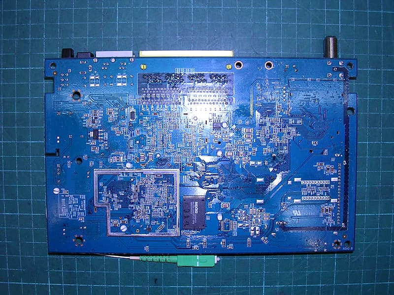
Click to zoom
Application Details
- Equipment Class
- NII - Unlicensed National Information Infrastructure TX
- Date of Grant
- Dec 29, 2009
- Application Purpose
- Original Equipment
- Date of Application
- Dec 28, 2009
- Equipment Note
- 802.11N GPON VoIP IAD
- Frequency Range
- 5180.00000000 - 5240.00000000
- Country
- Taiwan
Documents & Files
Document Text
Text extracted from the exhibit documents filed with the FCC. Open a document above to read the original.
Users Manual
www.zyxel.com www.zyxel.com P-3202HN-Ba 802.11N GPON VoIP IAD Copyright © 2009 ZyXEL Communications Corporation Version 1.0 Edition 1, 12/2009 Default Login Details IP Address192.168.1.1 User Nameadmin Password1234 About This User's Guide IAD User’s Guide 3 About This User's Guide Intended Audience This manual is intended for people who want to configure the IAD using the web configurator. . Related Documentation •Quick Start Guide The Quick Start Guide is designed to help you get your IAD up and running right away. It contains information on setting up your network and configuring for Internet access. • Web Configurator Online Help The embedded Web Help contains descriptions of individual screens and supplementary information. • Support Disc Refer to the included CD for support documents. Documentation Feedback Send your comments, questions or suggestions to: [email protected] Thank you! The Technical Writing Team, ZyXEL Communications Corp., 6 Innovation Road II, Science-Based Industrial Park, Hsinchu, 30099, Taiwan. Need More Help? More help is available at www.zyxel.com. About This User's Guide IAD User’s Guide 4 • Download Library Search for the latest product updates and documentation from this link. Read the Tech Doc Overview to find out how to efficiently use the documentation in order to better understand how to use your product. • Knowledge Base If you have a specific question about your product, the answer may be here. This is a collection of answers to previously asked questions about ZyXEL products. •Forum This contains discussions on ZyXEL products. Learn from others who use ZyXEL products and share your experiences as well. Customer Support Should problems arise that cannot be solved by the methods listed above, you should contact your vendor. If you cannot contact your vendor, then contact a ZyXEL office for the region in which you bought the device. See http://www.zyxel.com/web/contact_us.php for contact information. Please have the following information ready when you contact an office. • Product model and serial number. •Warranty Information. • Date that you received your device. • Brief description of the problem and the steps you took to solve it. Document Conventions IAD User’s Guide 5 Document Conventions Warnings and Notes These are how warnings and notes are shown in this User’s Guide. Warnings tell you about things that could harm you or your device. Note: Notes tell you other important information (for example, other things you may need to configure or helpful tips) or recommendations. Syntax Conventions • This product may be referred to as the “IAD”, the “device” or the “system” in this User’s Guide. • Product labels, screen names, field labels and field choices are all in bold font. • A key stroke is denoted by square brackets and uppercase text, for example, [ENTER] means the “enter” or “return” key on your keyboard. • “Enter” means for you to type one or more characters and then press the [ENTER] key. “Select” or “choose” means for you to use one of the predefined choices. • A right angle bracket ( > ) within a screen name denotes a mouse click. For example, Maintenance > Log > Log Setting means you first click Maintenance in the navigation panel, then the Log sub menu and finally the Log Setting tab to get to that screen. • Units of measurement may denote the “metric” value or the “scientific” value. For example, “k” for kilo may denote “1000” or “1024”, “M” for mega may denote “1000000” or “1048576” and so on. • “e.g.,” is a shorthand for “for instance”, and “i.e.,” means “that is” or “in other words”. Document Conventions IAD User’s Guide 6 Icons Used in Figures Figures in this User’s Guide may use the following generic icons. The IAD icon is not an exact representation of your device. IADComputerNotebook computer ServerDSLAMFirewall Te l e p h o n eSwitchRouter Safety Warnings IAD User’s Guide 7 Safety Warnings • Do NOT use this product near water, for example, in a wet basement or near a swimming pool. • Do NOT expose your device to dampness, dust or corrosive liquids. • Do NOT store things on the device. • Do NOT install, use, or service this device during a thunderstorm. There is a remote risk of electric shock from lightning. • Connect ONLY suitable accessories to the device. • Do NOT open the device or unit. Opening or removing covers can expose you to dangerous high voltage points or other risks. ONLY qualified service personnel should service or disassemble this device. Please contact your vendor for further information. • Make sure to connect the cables to the correct ports. • Place connecting cables carefully so that no one will step on them or stumble over them. • Always disconnect all cables from this device before servicing or disassembling. • Use ONLY an appropriate power adaptor or cord for your device. • Connect the power adaptor or cord to the right supply voltage (for example, 110V AC in North America or 230V AC in Europe). • Do NOT allow anything to rest on the power adaptor or cord and do NOT place the product where anyone can walk on the power adaptor or cord. • Do NOT use the device if the power adaptor or cord is damaged as it might cause electrocution. • If the power adaptor or cord is damaged, remove it from the device and the power source. • Do NOT attempt to repair the power adaptor or cord. Contact your local vendor to order a new one. • Do not use the device outside, and make sure all the connections are indoors. There is a remote risk of electric shock from lightning. • Do NOT obstruct the device ventilation slots, as insufficient airflow may harm your device. • Use only No. 26 AWG (American Wire Gauge) or larger telecommunication line cord. • Antenna Warning! This device meets ETSI and FCC certification requirements when using the included antenna(s). Only use the included antenna(s). • If you wall mount your device, make sure that no electrical lines, gas or water pipes will be damaged. Your product is marked with t…
Text truncated - open the document above for the full version.
Users Manual
Appendix B Setting Up Your Computer’s IP Address IAD User’s Guide 251 6Select Internet Protocol Version 4 (TCP/IPv4) and then select Properties. Figure 131 Windows Vista: Local Area Connection Properties Appendix B Setting Up Your Computer’s IP Address IAD User’s Guide 252 7The Internet Protocol Version 4 (TCP/IPv4) Properties window opens. Figure 132 Windows Vista: Internet Protocol Version 4 (TCP/IPv4) Properties 8Select Obtain an IP address automatically if your network administrator or ISP assigns your IP address dynamically. Select Use the following IP Address and fill in the IP address, Subnet mask, and Default gateway fields if you have a static IP address that was assigned to you by your network administrator or ISP. You may also have to enter a Preferred DNS server and an Alternate DNS server, if that information was provided.Click Advanced. 9Click OK to close the Internet Protocol (TCP/IP) Properties window. 10Click OK to close the Local Area Connection Properties window. Verifying Settings 1Click Start > All Programs > Accessories > Command Prompt. Appendix B Setting Up Your Computer’s IP Address IAD User’s Guide 253 2In the Command Prompt window, type "ipconfig" and then press [ENTER]. You can also go to Start > Control Panel > Network Connections, right-click a network connection, click Status and then click the Support tab to view your IP address and connection information. Windows 7 This section shows screens from Windows 7 Enterprise. 1Click Start > Control Panel. Figure 133 Windows 7: Start Menu 2In the Control Panel, click View network status and tasks under the Network and Internet category. Figure 134 Windows 7: Control Panel Appendix B Setting Up Your Computer’s IP Address IAD User’s Guide 254 3Click Change adapter settings. Figure 135 Windows 7: Network And Sharing Center 4Double click Local Area Connection and then select Properties. Figure 136 Windows 7: Local Area Connection Status Note: During this procedure, click Continue whenever Windows displays a screen saying that it needs your permission to continue. Appendix B Setting Up Your Computer’s IP Address IAD User’s Guide 255 5Select Internet Protocol Version 4 (TCP/IPv4) and then select Properties. Figure 137 Windows 7: Local Area Connection Properties Appendix B Setting Up Your Computer’s IP Address IAD User’s Guide 256 6The Internet Protocol Version 4 (TCP/IPv4) Properties window opens. Figure 138 Windows 7: Internet Protocol Version 4 (TCP/IPv4) Properties 7Select Obtain an IP address automatically if your network administrator or ISP assigns your IP address dynamically. Select Use the following IP Address and fill in the IP address, Subnet mask, and Default gateway fields if you have a static IP address that was assigned to you by your network administrator or ISP. You may also have to enter a Preferred DNS server and an Alternate DNS server, if that information was provided. Click Advanced if you want to configure advanced settings for IP, DNS and WINS. 8Click OK to close the Internet Protocol (TCP/IP) Properties window. 9Click OK to close the Local Area Connection Properties window. Verifying Settings 1Click Start > All Programs > Accessories > Command Prompt. 2In the Command Prompt window, type "ipconfig" and then press [ENTER]. Appendix B Setting Up Your Computer’s IP Address IAD User’s Guide 257 3The IP settings are displayed as follows. Figure 139 Windows 7: Internet Protocol Version 4 (TCP/IPv4) Properties Mac OS X: 10.3 and 10.4 The screens in this section are from Mac OS X 10.4 but can also apply to 10.3. 1Click Apple > System Preferences. Figure 140 Mac OS X 10.4: Apple Menu Appendix B Setting Up Your Computer’s IP Address IAD User’s Guide 258 2In the System Preferences window, click the Network icon. Figure 141 Mac OS X 10.4: System Preferences 3When the Network preferences pane opens, select Built-in Ethernet from the network connection type list, and then click Configure. Figure 142 Mac OS X 10.4: Network Preferences Appendix B Setting Up Your Computer’s IP Address IAD User’s Guide 259 4For dynamically assigned settings, select Using DHCP from the Configure IPv4 list in the TCP/IP tab. Figure 143 Mac OS X 10.4: Network Preferences > TCP/IP Tab. 5For statically assigned settings, do the following: •From the Configure IPv4 list, select Manually. •In the IP Address field, type your IP address. •In the Subnet Mask field, type your subnet mask. Appendix B Setting Up Your Computer’s IP Address IAD User’s Guide 260 •In the Router field, type the IP address of your device. Figure 144 Mac OS X 10.4: Network Preferences > Ethernet 6Click Apply Now and close the window. Verifying Settings Check your TCP/IP properties by clicking Applications > Utilities > Network Utilities, and then selecting the appropriate Network Interface from the Info tab. Figure 145 Mac OS X 10.4: Network Utility Appendix B Setting Up Your Computer’s IP Address IAD User’s Guide 261 Mac OS X: 10.5 and 10.6 The screens in this section are from Mac OS X 10.5 but can also apply to 10.6. 1Click Apple > System Preferences. Figure 146 Mac OS X 10.5: Apple Menu 2In System Preferences, click the Network icon. Figure 147 Mac OS X 10.5: Systems Preferences Appendix B Setting Up Your Computer’s IP Address IAD User’s Guide 262 3When the Network preferences pane opens, select Ethernet from the list of available connection types. Figure 148 Mac OS X 10.5: Network Preferences > Ethernet 4From the Configure list, select Using DHCP for dynamically assigned settings. 5For statically assigned settings, do the following: •From the Configure list, select Manually. •In the IP Address field, enter your IP address. •In the Subnet Mask field, enter your subnet mask. Appendix B Setting Up Your Computer’s IP Address IAD User’s Guide 263 •In the Router field, enter the IP address of your IAD. Figure 149 Mac OS X 10.5: Network Preferences > Ethernet 6Click Apply and close the window. Appendix B Setting Up Your Computer’s IP Address IAD User’s Guide 264 Verifying…
Text truncated - open the document above for the full version.
Cover Letter(s)
Letter of Agency "I, an officer of ZyXEL Communications Corporation do hereby authorize Rico Deng, who is Senior Engineer in Intertek Testing Services Taiwan Ltd. to act on our behalf in front of the Federal Communications Commission with respect to all matters relating to certification of equipment under Part 15 and Part 18 of the FCC Rules until further notice." I further certify that no party (as defined in §1.2002(b) of CFR 47, 1992) to this application, including myself, is subject to a denial of federal benefits, that includes FCC benefits, pursuant to Section 5301 of the Anti-Drug Abuse Act of 1988, 21 U.S.C.,853(a). By: Wang Yi Signature Printed Title: Section Manager Date: 2009-12-08
Cover Letter(s)
Attestation for FCC Declaration of Conformity FCC ID: I88P3202HNBA Date: 2009-12-08 Please be notified that we, the undersigned, ZyXEL Communications Corporation declares that the product which bears the above FCC ID is also compliant with the FCC requirements for DoC. The test report number supporting the DoC is TS09110039-EME. Testing in regards to this report was done by Intertek Testing Service Ltd., located at No. 11, Lane 275, Ko Nan 1st Street, Shiang-Shan District, Hsinchu Taiwan, which has been accredited in accordance to all of the requirements of 47CFR 2.948 (d) and (e) of the FCC rules and KDB349827. Sincerely, Printed name: Wang Yi Position: Section Manager ZyXEL Communications Corporation Tel: +886-3-5783942 Fax: +886-3-578-2439 Email: [email protected]
Cover Letter(s)
Confidential Letter (Permanent) Attention: Application Examiner Re: Request for confidentiality Applicant: ZyXEL Communications Corporation FCC ID: I88P3202HNBA To whom it may concern, Request is hereby submitted by ZyXEL Communications Corporation to withhold permanently from public review certain portions of the application for equipment certification for the referenced FCC identifiers. This request for confidentiality is made pursuant to 47 CFR 0.457(d) of the FCC Rules. In particular, the following sections of the application are to be kept permanently confidential: [Select one or more of items below, as appropriate] • Schematics • Detailed Block diagrams • Detailed Operational/Functional Description Rationale for request for confidentiality: ZyXEL Communications Corporation has invested considerable time and materials in research and development to produce the referenced product. Disclosure of the permanently confidential portions of this application to competitors would not only give them significant competitive advantages in developing similar products, but would also disclose successful implementation of unpublished, leading edge technology developed by us. If you have questions or need further information, please contact the undersigned. Sincerely, Title: Section Manager Company name: ZyXEL Communications Corporation Date: 2009-12-08
ID Label/Location Info
Please see the next page FCC ID Label Location
Internal Photos
Photo 1: Internal photo of EUT Photo 2: Internal photo of EUT Photo 3: Internal photo of EUT Photo 4: Internal photo of EUT Photo 5: Internal photo of EUT Photo 6: Internal photo of EUT Photo 7: Internal photo of EUT DAC0 DAC1
RF Exposure Info
FCC ID. : I88P3202HNBA Report No.: TS09110042-EME Page 1 of 8 Maximum Permissible Exposure (MPE) Evaluation Report Report No. : TS09110042-EME Model No. : P-3202HN-Ba, -3202HN-Bb Issued Date : Dec. 11, 2009 Applicant: ZyXEL Communications Corporation 6, Innovation Rd II, Science-Based Industrial Park, Hsin-Chu, Taiwan Te s t M e t h o d / Standard: FCC 1.1310 and Safety Code 6 Test By: Intertek Testing Services Taiwan Ltd. No. 11, Lane 275, Ko-Nan 1 Street, Chia-Tung Li, Shiang-Shan District, Hsinchu City, Taiwan It may be duplicated completely for legal use with the allowance of the applicant. It shall not be reproduced except in full, without the written approval of Intertek Laboratory. The test result(s) in this report only applies to the tested sample(s). The test report was prepared by: Sign on File Shirla Hsiao / Officer These measurements were taken by: Sign on File Rex Liao / Engineer The test report was reviewed by: Name Rico Deng Title Senior Engineer FCC ID. : I88P3202HNBA Report No.: TS09110042-EME Page 2 of 8 Table of Contents Summary of Tests ............................................................................................................. 3 1. Introduction .................................................................................................................. 4 1.1 Additional information about the EUT ................................................................... 4 2. RF Exposure Limit ....................................................................................................... 5 3. RF Exposure calculations ............................................................................................. 6 4. Test results .................................................................................................................... 7 FCC ID. : I88P3202HNBA Report No.: TS09110042-EME Page 3 of 8 Summary of Tests MPE Evaluation meet FCC OET No. 65: 1997, IEEE C95.1-2005 and IC Safety Code 6 GPON IAD - Model: P-3202HN-Ba FCC ID: I88P3202HNBA Test Reference Results MPE Evaluation FCC Guidelines for Human Exposure IEEE C95.1 and IC Safety Code 6 Complies FCC ID. : I88P3202HNBA Report No.: TS09110042-EME Page 4 of 8 1. Introduction The EUT operates in the 2.4 GHz ISM band and 5 GHz band. Due to the EUT (include antenna) at its normal operation distance is at least 20 cm from the human body, the EUT was defined as a Mobile Device. The reason to do the MPE Evaluation is to avoid the RF hazard to human body. The maximum output power and gain of the antenna were used to calculate the limited Power density (S) at 20 cm distance away from the product. The limit for Maximum Permissible Exposure (MPE) specified in FCC 1.1310 and Safety Code 6 are followed. According to 1.1307 (b)(1), systems operating under the provisions of this section shall be operated in a manner that ensure that the public is not exposed to radio frequency energy level in excess of the Commission’s guideline. 1.1 Additional information about the EUT The EUT is a GPON IAD which is a 802.11 a/b/g/n MIMO product with dual transmitters and dual receivers. The 802.11a/g/n function which can transmit independently and simultaneous transmit The customer confirmed the model listed below was a series model to model P-3202HN-Ba (EUT), the differences are listed below. Model Number Differences P-3202HN-Ba with CATV interface, with Fiber interface P-3202HN-Bb with Fiber interface, no CATV interface For more detail features, please refer to User's manual as file name “Installation guide.pdf”. FCC ID. : I88P3202HNBA Report No.: TS09110042-EME Page 5 of 8 2. RF Exposure Limit For FCC: According to FCC 1.1310: The criteria listed in the following table shall be used to evaluate the environmental impact of human exposure to radio-frequency (RF) radiation as specified in 1.1307(b). Limits for Maximum Permissible Exposure (MPE) Frequency Range (MHz) Electric Field Strength (V/m) Magnetic Field Strength (A/m) Power Density (mW/cm 2 ) Average Time (minutes) (A) Limits for Occupational / Control Exposures 30-300 61.4 0.163 1.0 6 300-1500 - - F/300 6 1500-100,000 - - 5 6 (B) Limits for General Population / Uncontrolled Exposure 30-300 27.5 0.073 0.2 30 300-1500 - - F/1500 30 1500-100,000 - - 1.0 30 F= Frequency in MHz FCC ID. : I88P3202HNBA Report No.: TS09110042-EME Page 6 of 8 For IC: Exposure Limits for Persons Not Classed As RF and Microwave Exposed Workers (Including the General Public) Frequency Range (MHz) Electric Field Strength; rms (V/m) Magnetic Field Strength; rms (A/m) Power Density (W/m 2 ) Average Time (minutes) 0.003-1 280 2.19 - 6 1-10 280/f 2.19/f - 6 10-30 28 2.19/f - 6 30-300 28 0.073 2 * 30 300-1500 1.585 f 0.5 0.0042 f 0.5 F/150 30 1500-15000 61.4 0.163 10 30 15000-150000 61.4 0.163 10 616000/f 1.2 150000-300000 0.158 f 0.5 4.21 × 10 -4 f 0.5 6.67 × 10 -5 f 616000/f 1.2 * Power density limit is applicable at frequencies greater than 100 MHz. Notes: 1. Frequency, f, is in MHz. 2. A power density of 10 W/m 2 is equivalent to 1 mW/cm 2 . 3. A magnetic field strength of 1 A/m corresponds to 1.257 microtesla (μT) or 12.57 milligauss (mG). 3. RF Exposure calculations From §FCC 1.1310 table 1 and §Safety Code 6 table 5, the maximum permissible RF exposure for an uncontrolled environment is 1 mW/(cm 2 ) (or 10 W/m 2 )* * 10 W/m 2 = 1 mW/ (cm 2 ) Power density (S) is calculated by the following formula: S = (P * G)/4πR 2 where, S = Power density (mW/cm 2 ) P = Output power to antenna (mW) R = Distance between radiating structure and observation point (cm) G = Gain of antenna in numeric π = 3.1416 Example: Assume a mobile device operates at 2412MHz and its maximum output power is 50mW, and the maximum gain of antenna is 1 (numeric) /0dBi. then the power density (S) = (50 * 1)/4*π*20 2 = 0.00995 (mW/cm 2 ) (or = 0.0995 W/m 2 ) FCC ID. : I88P3202HNBA Report No.: TS09110042-EME Page 7 of 8 4. Test results Single Tx Mode Channel Frequency (MHz) Antenna Gain (numeric) Output power to antenna (mW…
Text truncated - open the document above for the full version.
Test Report
FCC ID. : I88P3202HNBA Report No.: TS09110041-EME Page 1 of 58 EMC TEST REPORT Report No. : TS09110041-EME Model No. : P-3202HN-Ba, P-3202HN-Bb Issued Date : Dec. 11, 2009 Applicant: ZyXEL Communications Corporation 6, Innovation Rd II, Science-Based Industrial Park, Hsin-Chu, Taiwan Test Method/ Standard: FCC Part 15 Subpart E Section §15.207、§15.209 、§15.407 and ANSI C63.4/2003. Test By: Intertek Testing Services Taiwan Ltd. No. 11, Lane 275, Ko-Nan 1 Street, Chia-Tung Li, Shiang-Shan District, Hsinchu City, Taiwan It may be duplicated completely for legal use with the allowance of the applicant. It shall not be reproduced except in full, without the written approval of Intertek Laboratory. The test result(s) in this report only applies to the tested sample(s). The test report was prepared by: Sign on File Shirla Hsiao / Officer These measurements were taken by: Sign on File Rex Liao / Engineer The test report was reviewed by: Name Jacky Chen Title Engineer FCC ID. : I88P3202HNBA Report No.: TS09110041-EME Page 2 of 58 Table of Contents Summary of Tests ...................................................................................................................... 3 1. General information .............................................................................................................. 4 1.1 Identification of the EUT ................................................................................................ 4 1.2 Additional information about the EUT............................................................................ 5 1.3 Antenna description.........................................................................................................6 1.4 Peripherals equipment ..................................................................................................... 6 2. Test specifications ................................................................................................................. 7 2.1 Test standard.................................................................................................................... 7 2.2 Operation mode ............................................................................................................... 8 2.3 Test equipment ................................................................................................................ 9 3. Peak Output Power test (FCC 15.407) ................................................................................ 10 3.1 Operating environment.................................................................................................. 10 3.2 Test setup & procedure .................................................................................................. 10 3.3 Limit .............................................................................................................................. 10 3.4 Measured data of Maximum Output Power test results ................................................ 10 4. Power Spectrum Density test (FCC 15.407) ....................................................................... 19 4.1 Operating environment.................................................................................................. 19 4.2 Test setup & procedure .................................................................................................. 19 4.3 Limitation ...................................................................................................................... 19 4.4 Measured data of Power Spectrum Density test results ................................................ 19 5. Additional provisions test (FCC 15.215)............................................................................. 28 5.1 Operating environment.................................................................................................. 28 5.2 Procedure of test setup & limitation.............................................................................. 28 5.3 Measured data of test results ......................................................................................... 29 6. Peak excursion to average ratio test (FCC 15.407) ............................................................. 32 6.1 Operating environment.................................................................................................. 32 6.2 Test setup & procedure .................................................................................................. 32 6.3 Limitation ...................................................................................................................... 32 6.4 Measured data of Peak excursion to average ratio test results ...................................... 32 7. Radiated Emission test (FCC 15.407(b), 15.205 & 15.209) ............................................... 41 7.1 Operating environment.................................................................................................. 41 7.2 Test setup & procedure .................................................................................................. 41 7.3 Emission limits .............................................................................................................. 42 7.4 Radiated spurious emission test data............................................................................. 43 7.4.1 Measurement results: frequencies equal to or less than 1 GHz.................................. 43 7.4.2 Measurement results: frequency above 1GHz ........................................................... 44 8. Emission on the band edge §FCC 15.205 ........................................................................... 47 8.1 Operating environment.................................................................................................. 47 8.2 Test setup & procedure .................................................................................................. 47 8.3 Test Result ............................…
Text truncated - open the document above for the full version.
Test Setup Photos
Photo 1: Conducted Emission Test Set-up photo Photo 2: Conducted Emission Test Set-up photo
Test Setup Photos
Photo 1: Radiated Emission Test set-up photo Photo 2: Radiated Emission Test set-up photo
Contact Information
Applicant
Emma Bao(Section Manager)
Technical Contact
Intertek Testing Services Taiwan Ltd.Rico Deng
[email protected](+886)-3-519-1411
11, Ln. 275, Ko Nan 1st Street · Hsinchu · Taiwan
Non-Technical Contact
Intertek Testing Services Taiwan Ltd.Rico Deng
[email protected](+886)-3-519-1411
Test Firm
Intertek Testing Services Taiwan Ltd.Lily Shih
Technical Specifications
| # | Rule Parts | Frequency Range | Power Output |
|---|---|---|---|
| 1 | 15E | 5.18 GHz - 5.24 GHz | 44.00 mW |
Other Applications from ZyXEL Communications Corporation
I88EE6601-00
Jul 18, 2024Tri-Band Wireless BE19000 10G Ethernet VoIP Gateway with SFP+ / Tri-Band Wireless BE19000 10G Ethernet VoIP Gateway / Tri-Band Wireless BE19000 10G Ethernet Gateway with SFP+ / Tri-Band Wireless BE19000 10G Ethernet Gateway
Equipment Class
6ID - 15E 6 GHz Low Power Indoor Access Point
I8803935
Oct 17, 2023802.11be (WiFi 7) Triple-Radio Unified Pro Access Point
Equipment Class
DTS - Digital Transmission System
I8803973
Aug 01, 2023802.11ax (WiFi 6) Dual-Radio Wall-Plate Unified Access Point
Equipment Class
NII - Unlicensed National Information Infrastructure TX
I88WX5610-B0
Apr 25, 2023AX7800 WiFi 6E Tri-Band Gigabit Wireless Extender
Equipment Class
DTS - Digital Transmission System
I88EX7710-B0
Apr 16, 2023AX11000 WiFi 6E 10G Ethernet Gateway
Equipment Class
NII - Unlicensed National Information Infrastructure TX