I88PK5000Z802.11g Wireless ADSL 2+ 4-port Gateway
ZyXEL Communications Corporation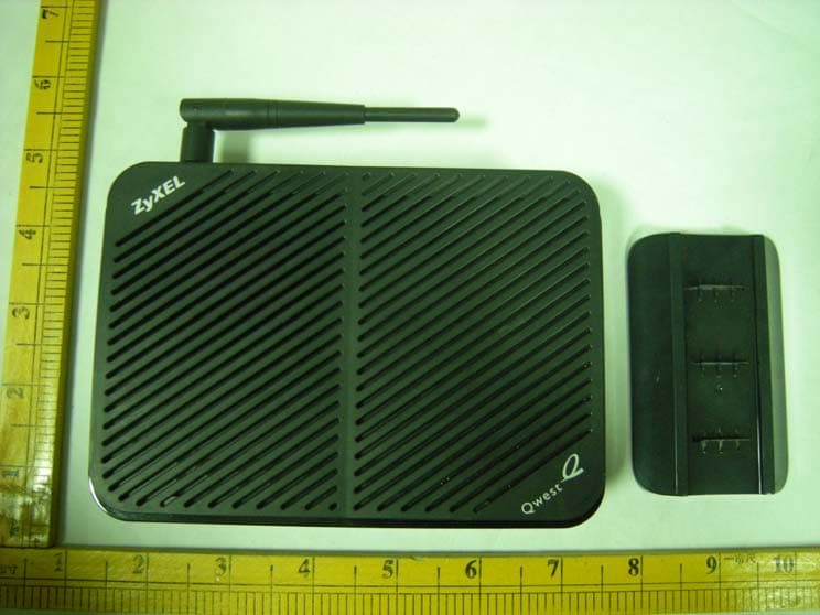
Click to zoom
Application Details
- Equipment Class
- DTS - Digital Transmission System
- Date of Grant
- Jan 11, 2010
- Application Purpose
- Original Equipment
- Date of Application
- Jan 11, 2010
- Equipment Note
- 802.11g Wireless ADSL 2+ 4-port Gateway
- Frequency Range
- 2412.00000000 - 2462.00000000
- Country
- Taiwan
Documents & Files
Document Text
Text extracted from the exhibit documents filed with the FCC. Open a document above to read the original.
Users Manual
PK5000Z 802.11g Wireless ADSL2+ 4-port Gateway Quick Start Guide Version 3.40 12/2009 Edition 1 PK5000Z Quick Start Guide 2 Overview The PK5000Z is a wireless ADSL router with a four-port built-in switch. This Quick Start Guide shows you how to use the PK5000Z to connect to the Internet and how to configure the device settings to connect wirelessly. See your User’s Guide for background information on all features. Quick Login Information LAN IP address http://192.168.0.1 default administrator password 1234 PK5000Z Quick Start Guide 3 1 Hardware Connections 1 DSL: Use the gray telephone wire to connect your PK5000Z’s DSL port to a telephone jack (or to the modem port on a splitter if you are using one). 2 ETHERNET: Use the yellow Ethernet cable to connect a computer to an ETHERNET port for initial configuration and/or Internet access. 3 POWER: Use the included power adaptor to connect an appropriate power source to the POWER socket. Make sure the power source is on. 4 Push in the POWER button. 5 Look at the lights on the front panel. • The POWER light blinks while your PK5000Z starts up and stays on once it is ready. • Each ETHERNET light stays on if the corresponding ETHERNET port is properly connected and blinks when there is traffic. • The DSL light is on when the PK5000Z has a DSL connection. • The INTERNET light is on when you are able to access the Internet and blinks when the PK5000Z is sending or receiving data. Wait a couple of minutes while your device checks the connection. If any of these lights are not on, check your connections and inspect your cables for damage. If the lights are still off, contact your local vendor. 2 Internet Connection Setup: Automatic Use this section to have your PK5000Z automatically detect and set up your Internet connection. 1 Open your web browser to a website. Wait while your PK5000Z tries to detect your DSL connection to your ISP. This may take a few minutes. 2 After it detects the connection, the DSL light shows green on your device and the Internet light comes on when the Internet is ready for you to use. If you have a PPPoE connection, you will have to enter your user name and password. 3 Go to section 3 if you wish to configure your wireless settings. 4 If you do not see the connection test screen, or the connection test is not successful, follow the instructions in the screen below, or check your connections and restart the PK5000Z. If you still cannot access the Internet, follow the steps in section 3. 3 Configuring your Wireless Settings To create a wireless network, the PK5000Z and your wireless computer must all use the same SSID (network name), channel and security settings. If you do not set wireless security then anyone within range could use your PK5000Z to access your network and the Internet. Choose WPA-PSK wireless security if your wireless device supports it as it is stronger than WEP. Otherwise choose WEP. PK5000Z Quick Start Guide 4 1 Select Active and click Next to continue. It is strongly recommended that Enable OTIST is NOT selected. See section 7 for more information. 2 Configure your wireless settings in the screen. Click Next. 3) If you select either WEP or WPA-PSK security (recommended), then follow the directions to enter the appropriate key. Click Next to continue and Apply to save your wireless LAN settings. 4 Check your configuration and write down your wireless LAN settings for later use. Click Finish to complete and save the wizard setup. 5 Your Internet is ready for you to use. Open your browser and navigate to your favorite website. 4 Internet Connection Setup Using Advanced Settings Use this section to set up your Internet connection manually if you do not see the ISP Parameters for Internet Access screen when you run the wizard (see section 4, step 4). 1 Login again. (Follow steps 1 to 5 in section 3.) 2 Select Go to Advanced setup. Then, click Apply. 3 The Status screen appears. Click Network > WAN in the navigation panel on the left of the screen. 4 Enter the information exactly as provided by your ISP. Click Apply. 5 If you still cannot access the Internet, see Troubleshooting and/or contact your Internet Service Provider (ISP) for assistance. PK5000Z Quick Start Guide 5 Troubleshooting 1 If you cannot access the web configurator, • Your computer may be set to use a static IP address in a different subnet from the ZyXEL device. See the appendix in the User’s Guide for information on setting up your IP address. • If you are using Internet Explorer in Windows XP or Windows Server 2003, make sure you allow pop-up windows, JavaScripts and Java permissions or set the Internet security level lower than High in Internet Explorer (in Internet Explorer, click Tools > Internet Options > Security > Custom Level...). See the appendix in the User’s Guide for more information. 2 If you cannot access the Internet when your computer is connected to the ETHERNET port, follow these steps. A) Check the lights on the front panel. If they are different from what is described in section 1, make sure the PK5000Z is correctly connected. (See section 1.) If the lights are still different, turn off the device, wait a few seconds, and turn it on again. B) Check you have correctly entered the informatinon your ISP gave you. For example, if your account has a user name and password, make sure you type it correctly. In addition, if you are not sure which encapsulation your ISP uses, contact your ISP. If your ISP did not give you Internet connection information, follow the steps in section 2. C) If you are using a new Internet account, contact your ISP to make sure it is active. D) If you still have problems, see Troubleshooting in the User’s Guide. If you cannot access the Internet after you take the steps above, either try the following or contact your ISP: E) Turn your PK5000Z off and on. Open your Internet browser if it is not already open. Let the PK5000Z complete the DSL connection test (this may take several minutes). See section 2…
Text truncated - open the document above for the full version.
Cover Letter(s)
Attestation for FCC Declaration of Conformity FCC ID: I88PK5000Z Date: Jan 05, 2010 Please be notified that we, the undersigned, Cerpass technology Coporation declares that the product which bears the above FCC ID is a;so compliant with the FCC requirements for DOC. The test report number supporting the DOC is SEFD0912034. Testing in regards to this report was done by Cerpass technology Coporation, located at No. 7-2, Moshihkeng, Fongtian Village, Shihding Township, Taipei County, Taiwan, R.O.C., which has been accredited in accordance to all of the requirements of 47 CFR 2.948(d) and(e)of the FCC rules and KDB349827. Sincerely, Anson Chou / Manager Tel: +886-2-26558100#5301 Fax: +886-2-26558200 Email: [email protected]
Cover Letter(s)
AHTHORIZATION LETTER FCC ID: I88PK5000Z Date: Jan 05, 2010 To whom it may concern: We, the undersigned, hereby authorize Cerpass Technology (Suzhou) Co., Ltd. of China to act on our behalf, as our agent, in the following matters related to the FCC approval of our products: report submittal, related correspondence, the signing of all documents relating to these matters, and any other lawful activity necessary to obtain such certification. Any act carried out by Cerpass Technology (Suzhou) Co., Ltd. within the scope of this authorization shall have the same effects as our own. This authorization shall expire 2 weeks from original data. If you have any questions regarding the authorization, please don’t hesitate to contact me. Thank you. Yours Sincerely, Engineer ZyXEL Communications Corporation
Cover Letter(s)
ZyXEL Communications Corporation Date: Jan 05, 2010 Federal Communications Commission Authorization and Evaluation Division FCC ID: I88PK5000Z Confidentiality Request Pursuant to Sections 0.457 and 0.459 of the Commission’s Rules, the Applicant hereby requests confidential treatment of information accompanying this Application as outlined below: 1 Schematics 2 Operational Description 3 Block Diagram. The above materials contain trade secrets and proprietary information not customarily released to the public. The public disclosure of these matters might be harmful to the Applicant and provide unjustified benefits to its competitors. The Applicant understands that pursuant to Rule 0.457, disclosure of this Application and all accompanying documentation will not be made before the date of the Grant for this application. Sincerely, Wang Yi , engineer ZyXEL Communications Corporation
External Photos
802.11g Wireless ADSL 2+ 4-port Gateway (Model name: PK5000Z) Exterior Photograph: 1) 2) 3) 4) 5) 5) 6) 7) 8)
ID Label/Location Info
802.11g Wireless ADSL 2+ 4-port Gateway (Model name: PK5000Z) FCC ID Position: FCC ID Lable
Internal Photos
802.11g Wireless ADSL 2+ 4-port Gateway (Model name: PK5000Z) Inside photo: 1) 2) 3) 4)
RF Exposure Info
RF Exposure Evaluation Declaration Product: 802.11g Wireless ADSL 2+ 4-port Gateway Test Item: RF Exposure Evaluation Declaration 1. RF Exposure Evaluation 1.1. Limits According to FCC 1.1310: The criteria listed in the following table shall be used to evaluate the environment impact of human exposure to radio frequency (RF) radiation as specified in 1.1307(b) LIMITS FOR MAXIMUM PERMISSIBLE EXPOSURE (MPE) Frequency Range (MHz) Electric Field Strength (V/m) Magnetic Field Strength (A/m) Power Density (mW/cm2) Average Time (Minutes) (A) Limits for Occupational/ Control Exposures 300-1500 -- -- F/300 6 1500-100,000 -- -- 5 6 (B) Limits for General Population/ Uncontrolled Exposures 300-1500 -- -- F/1500 6 1500-100,000 -- -- 1 30 F= Frequency in MHz Friis Formula Friis transmission formula: Pd = (Pout*G)/(4*pi*r2) Where Pd = power density in mW/cm2 Pout = output power to antenna in mW G = gain of antenna in linear scale Pi = 3.1416 R = distance between observation point and center of the radiator in cm Pd id the limit of MPE, 1 mW/cm2 . If we know the maximum gain of the antenna and the total power input to the antenna, through the calculation, we will know the distance r where the MPE limit is reached. Report No: 0903042-RF-US-W Page: 2 of 2 1.2. Test Procedure Software provided by client enabled the EUT to transmit and receive data at lowest, middle and highest channel individually. The temperature and related humidity: 18°Cand 78% RH. 1.3. EUT Operation condition Software provided by client enabled the EUT to transmit and receive data at lowest, middle and highest channel individually. 1.4. Test Result of RF Exposure Evaluation Antenna Gain: Antenna Gain: The maximum Gain is 2.79 dBi. Output Power Into Antenna & RF Exposure Evaluation Distance: 1) 802.11b Test date: Channel Channel Frequency (MHz) Output Power to Antenna (mW) Power Density at R = 20 cm (mW/cm2) 01 2412.00 66.2217 0.0250454 06 2437.00 108.3927 0.0409947 11 2462.00 74.4732 0.0281661 2) 802.11g Test date: Channel Channel Frequency (MHz) Output Power to Antenna (mW) Power Density at R = 20 cm (mW/cm2) 01 2412.00 77.8037 0.0294257 06 2437.00 143.5489 0.0542909 11 2462.00 86.2979 0.0326383 Note: The power density Pd (4th column) at a distance of 20 cm calculated from the Friis transmission formula is far below the limit of 1 mW/cm2.
Test Report
CERPASS TECHNOLOGY CORP. Report No.: SEFI0912034 Cerpass Technology Corp. Issued Date : Dec 31.2009 Tel:86-512-6917-5888 Fax: 86-512-6917-5666 Page No. : 1 of 82 FCC TEST REPORT According to FCC CFR Title 47 Part 15 Subpart C Applicant : ZyXEL Communications Corp. Address : 6 innovation RD II, science park, hsinchu 300, TaiWan Manufacturer(1) : ZyXEL Communications Corp. Address(1) : 6 innovation RD II, science park, hsinchu 300, TaiWan Manufacturer(2) : ZyXEL Communications(Wuxi) Co Ltd. Address(2) : 60 – E, Minshan RD, New District, Wuxi, Jiangsu, P.R. China Equipment : 802.11g Wireless ADSL 2+ 4-port Gateway Model No. : PK5000Z FCC ID : I88PK5000Z The test result refers exclusively to the test presented test model / sample. Without written approval of Cerpass Technology Corp. the test report shall not be reproduced except in full. The test report must not be used by the clients to claim product certification approval by NVLAP or any agency of the Government. CERPASS TECHNOLOGY CORP. Report No.: SEFI0912034 Cerpass Technology Corp. Issued Date : Dec 31.2009 Tel:86-512-6917-5888 Fax: 86-512-6917-5666 Page No. : 2 of 82 Table of Contents 1. Report of Measurements and Examinations.............................................................................................6 2. Test Configuration of Equipment under Test............................................................................................7 2.1. Feature of Equipment under Test .................................................................................................... 7 2.2. Carrier Frequency of Channels ....................................................................................................... 8 2.3. Carrier Frequency of Channels ....................................................................................................... 8 2.4. Test Manner ..................................................................................................................................... 9 2.5. Description of Test System .............................................................................................................. 9 2.6. Connection Diagram of Test System ............................................................................................. 10 2.7. General Information of Test ............................................................................................................11 2.8. Measurement Uncertainty ..............................................................................................................11 3. Test of Conducted Emission ....................................................................................................................12 3.1. Test Limit........................................................................................................................................ 12 3.2. Test Procedures............................................................................................................................. 12 3.3. Typical Test Setup.......................................................................................................................... 13 3.4. Measurement Equipment .............................................................................................................. 13 3.5. Test Result and Data ..................................................................................................................... 14 4. Test of Radiated Emission ........................................................................................................................16 4.1. Test Limit........................................................................................................................................ 16 4.2. Test Procedures............................................................................................................................. 16 4.3. Typical Test Setup.......................................................................................................................... 17 4.4. Measurement Equipment .............................................................................................................. 18 4.5. Test Result and Data ..................................................................................................................... 19 5. Occupied Bandwidth .................................................................................................................................55 5.1. Test Limit........................................................................................................................................ 55 5.2. Test Procedures............................................................................................................................. 55 5.3. Test Setup Layout .......................................................................................................................... 55 5.4. Measurement Equipment .............................................................................................................. 55 5.5. Test Result and Data ..................................................................................................................... 56 6. Maximum Peak Output Power ..................................................................................................................60 6.1. Test Limit........................................................................................................................................ 60 6.2. Test Procedure .............................................................................................................................. 60 6.3. Test Setup Layout .......................................................................................................................... 61 6.4. Measurement Equipment .............................................................................................................. 61 6…
Text truncated - open the document above for the full version.
Test Setup Photos
802.11g Wireless ADSL 2+ 4-port Gateway (Model name: PK5000Z) Test Photograph: Front View of Conducted Emission Test Back View of Conducted Emission Test Front View of Radiated Emission Test Back View of Radiated Emission Test
Contact Information
Applicant
Emma Bao(Section Manager)
Technical Contact
Cerpass Technology CorporationJohn. wang
[email protected]+86-512-69175888
No.66, Tangzhuang Road · JiangSu · China
Test Firm
Cerpass Technology (SuZhou) Co., Ltd.Alex Chiu
Technical Specifications
| # | Rule Parts | Frequency Range | Power Output |
|---|---|---|---|
| 1 | 15C | 2.41 GHz - 2.46 GHz | 144.00 mW |
Other Applications from ZyXEL Communications Corporation
I88EE6601-00
Jul 18, 2024Tri-Band Wireless BE19000 10G Ethernet VoIP Gateway with SFP+ / Tri-Band Wireless BE19000 10G Ethernet VoIP Gateway / Tri-Band Wireless BE19000 10G Ethernet Gateway with SFP+ / Tri-Band Wireless BE19000 10G Ethernet Gateway
Equipment Class
6ID - 15E 6 GHz Low Power Indoor Access Point
I8803935
Oct 17, 2023802.11be (WiFi 7) Triple-Radio Unified Pro Access Point
Equipment Class
DTS - Digital Transmission System
I8803973
Aug 01, 2023802.11ax (WiFi 6) Dual-Radio Wall-Plate Unified Access Point
Equipment Class
NII - Unlicensed National Information Infrastructure TX
I88WX5610-B0
Apr 25, 2023AX7800 WiFi 6E Tri-Band Gigabit Wireless Extender
Equipment Class
DTS - Digital Transmission System
I88EX7710-B0
Apr 16, 2023AX11000 WiFi 6E 10G Ethernet Gateway
Equipment Class
NII - Unlicensed National Information Infrastructure TX