IBQACMI005Speed SensorRadar
Applied Concepts Inc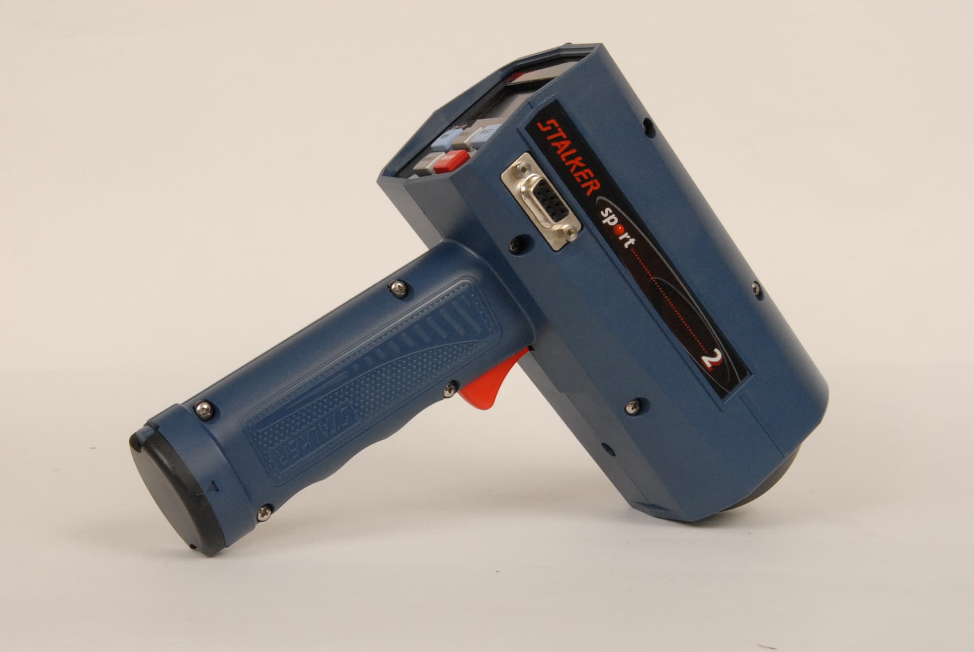
Click to zoom
Application Details
- Equipment Class
- FDS - Part 15 Field Disturbance Sensor
- Date of Grant
- Sep 27, 2007
- Application Purpose
- Original Equipment
- Date of Application
- Sep 27, 2007
- Equipment Note
- Speed SensorRadar
- Frequency Range
- 24125.00000000 - 24125.00000000
- Company
- Applied Concepts Inc
- Country
- United States
Documents & Files
Document Text
Text extracted from the exhibit documents filed with the FCC. Open a document above to read the original.
Users Manual
S Sport2 Digital Sports Radar Owner’s Manual Not intended for Law Enforcement use This device complies with Part 15 of the FCC Rules. Operation is subject to the following two conditions: (1) This device may not cause harmful interference, and (2) this device must accept any interference received, including interference that may cause undesired operation. Changes or modifications not expressly approved by the manufacturer may void the user's right to operate the equipment. TABLE OF CONTENTS SPORT2 Owner’s Manual Table of Contents............................................................................................................................ 1 Introduction...................................................................................................................................... 2 What IS Included............................................................................................................................. 3 Quick START Instructions............................................................................................................... 4 Controls and Indicators.................................................................................................................... 5 Detailed Instructions........................................................................................................................ 7 Providing Power to the Sport2.................................................................................................... 7 Turning the Transmitter ON and OFF......................................................................................... 7 Using the Trigger to Lock Speeds............................................................................................... 7 The RECALL Key Function......................................................................................................... 7 The Peak Function...................................................................................................................... 8 The Sport2 Operator Setup Menu............................................................................................... 8 The Sport 2 Option Setup Menu................................................................................................. 9 Target Speed Settings............................................................................................................... 11 Recommended Settings................................................................................................................ 12 Battery Information........................................................................................................................ 13 Angle Error..................................................................................................................................... 14 Interference Problems................................................................................................................... 15 Sport2 Accessories....................................................................................................................... 16 Service Information........................................................................................................................ 17 Specifications................................................................................................................................. 18 S RADAR 2609 Technology Drive Plano, TX 75074 1-888-STALKER (972) 398-3760 Sales (972) 398-3781 Fax www.stalkerradar.com S Sport2 Owner’s Manual INTRODUCTION Congratulations! You have purchased the finest sports radar system available. The Stalker Sport 2 K band sports radar is designed to measure the speed of a wide variety of objects such as baseballs, carnival balls, cars, tennis, and just about anything that moves. The Stalker Sport 2 radar sends out very high frequency radio waves and measures the change in the frequency after it bounces off a moving object. This is commonly referred to as “Doppler Radar.” This invisible radio wave is extremely low power (about 1/200th of a watt) and is completely safe for close and continuous operation. The Stalker Sport 2 is a true “digital” radar system. The Sport 2 converts the reflected microwave signals into a digital stream of data. The gun’s own computer then processes this data stream using sophisticated programming, to interpret, filter, and measure the speeds. This technology is closely related to the compact digital disc and modern personal computers. This type of radar system has the potential to provide substantially superior performance and accuracy over conventional radar systems. While the technology in the Stalker Sport 2 is extremely advanced, its operation is quite simple. Reading through this manual will help you to take full advantage of the many features and capabilities of the Stalker Sport 2 radar. Have Fun! 2 S Sport2 Owner’s Manual WHAT IS INCLUDED The components included with your radar are listed below. If you are missing any parts or if you would like to upgrade your package, contact Stalker Radar at 1-888-782-5537. SPORT2 PACKAGE - K-Band Radar Gun - Robust Battery Cover - 6-AA NiMH Batteries (rechargeable) - Wall Charger - Radar Manual - Hard Case 3 S Sport2 Owner’s Manual QUICK START INSTRUCTIONS The S Sport 2 (Sport 2) has several features that allow the gun to work well in a wide variety of applications. With some basic understanding, the gun is very simple to operate. Basic Operation 1. Power is supplied by 6 NiMH batteries located in the handle. 2. Turn the gun ON by pressing the ON/OFF button. 3. Squeeze the trigger to begin operating (transmitting). Important Settings There are four buttons that control the radar gun functions. The blue buttons and the silver buttons work together. MENU (Blue Button) - This feature sets the configuration for the radar to look for specific types of targets and certain speed ranges. SELECT (Blue Button) – When the Menu …
Text truncated - open the document above for the full version.
ID Label/Location Info
11 22 33 44 55 66 77 88 A A B B C C D D applied concepts, inc. SIZE DWG NO REV SCALE SHEET OF DRAWN BY DESIGNER/CHECK ENGINEERING DEPT DATES APPROVALS MFG ENG DEPT TITLE UNLESS OTHERWISE SPECIFIED ALL DIMS ARE IN INCHES. DIMS INCLUDE CHEM APPLIED OR PLATED SURFACE THICKNESS. REMOVE BURRS & SHARP EDGES. MATERIAL: SEE NOTE THIRD ANGLE PROJECTION .XX = ` .01 FRACT = 1/32 .XXX = ` .005 SURFACES 63 ANGLES = ` .5 TOLERANCES FINISH: SEE NOTE REVISIONS REV ZONE DESCRIPTION BY DATE LABEL, SERIAL NUMBER, SPORT 2 057-1313-00 1 1 B B 3/12/2007 ED RASMUSSEN 4:1 A B PROTOTYPE RELEASECHG FREQ FROM 24.15 GHZ ED R ED R 3-12-07 6-11-07 PLANO, TEXAS 75074 FCC ID: IBQACMI005 APPLIED CONCEPTS, INC. SPORT 2 RADAR 24.125 GHZ, S.N.: SKXXXXXX 2.000 .500 R.030 4X NOTE: 1. MATERIAL TO BE .002 THICK WHITE POLYESTER BONDED TO .007 CLEAR POLYESTER. 2. BACK SIDE TO HAVE PRESSURE SENSITIVE ADHESIVE WITH RELEASE LINER, 3M 9502 OR EQUIVALENT. 3. PART TO HAVE WHITE LETTERING ON BLACK BACKGROUND. ALL TEXT TO BE ARIAL. 4. VENDOR GENERATED ARTWORK TO BE APPROVED BY APPLIED CONCEPTS. 5. BARCODE TO BE 8 DIGIT CODE 39, WITH "SK" AS THE FIRST TWO DIGITS. S.N. TO CORRESPOND TO BARCODE. SERIAL NUMBER SEQUENCE TO BE SPECIFIED AT TIME OF ORDER. CODE 39 BARCODE OF SEQUENTIAL NUMBER. BLACK BARCODE LINESON WHITE RECTANGLE. REPLACE XXXXXX WITH SEQUENTIAL NUMBER SUPPLIED. BLACK BACKGROUND WHITE LINE 11 22 33 44 55 66 77 88 A A B B C C D D applied concepts, inc. SIZE DWG NO REV SCALE SHEET OF DRAWN BY DESIGNER/CHECK ENGINEERING DEPT DATES APPROVALS MFG ENG DEPT TITLE UNLESS OTHERWISE SPECIFIED ALL DIMS ARE IN INCHES. DIMS INCLUDE CHEM APPLIED OR PLATED SURFACE THICKNESS. REMOVE BURRS & SHARP EDGES. MATERIAL: SEE NOTE THIRD ANGLE PROJECTION .XX = ` .01 FRACT = 1/32 .XXX = ` .005 SURFACES 63 ANGLES = ` .5 TOLERANCES FINISH: SEE NOTE REVISIONS REV ZONE DESCRIPTION BY DATE LABEL, SERIAL NUMBER, SOLO 2 057-1314-00 1 1 B B 3/12/2007 ED RASMUSSEN 4:1 A B PROTOTYPE RELEASECHG FREQ FROM 24.15 GHZ ED R ED R 3-12-07 6-11-07 PLANO, TEXAS 75074 FCC ID: IBQACMI005 APPLIED CONCEPTS, INC. SOLO 2 RADAR 24.125 GHZ, S.N.: SLXXXXXX 2.000 .500 R.030 4X NOTE: 1. MATERIAL TO BE .002 THICK WHITE POLYESTER BONDED TO .007 CLEAR POLYESTER. 2. BACK SIDE TO HAVE PRESSURE SENSITIVE ADHESIVE WITH RELEASE LINER, 3M 9502 OR EQUIVALENT. 3. PART TO HAVE WHITE LETTERING ON BLACK BACKGROUND. ALL TEXT TO BE ARIAL. 4. VENDOR GENERATED ARTWORK TO BE APPROVED BY APPLIED CONCEPTS. 5. BARCODE TO BE 8 DIGIT CODE 39, WITH "SL" AS THE FIRST TWO DIGITS. S.N. TO CORRESPOND TO BARCODE. SERIAL NUMBER SEQUENCE TO BE SPECIFIED AT TIME OF ORDER. CODE 39 BARCODE OF SEQUENTIAL NUMBER. BLACK BARCODE LINESON WHITE RECTANGLE. REPLACE XXXXXX WITH SEQUENTIAL NUMBER SUPPLIED. BLACK BACKGROUND WHITE LINE Label location
Parts List/Tune Up Info
Tune-up Procedure for the Sport2 Microwave Assembly 1. Purpose Make adjustments to the Sport2 microwave assembly to insure that the Gunn oscillator output is 24.125GHz. 2. Equipment Power Supply and leads capable of 10VDC output. RF Frequency Counter Allen wrench, 0.050” 3. Equipment set-up Adjust power supply to 10VDC. Connect power supply leads to battery terminals of unit under test (UUT). Connect the minus and plus leads per figure. 4. Adjustment procedure. Aim the antenna at the RF frequency counter horn. Turn the adjustment screw (see figure) to obtain 24.125GHz on the frequency counter.
Test Report
This report and the information contained herein represent the results of testing test articles identified and selected by the client performed to specifications and/or procedures selected by the client. National Technical Systems (NTS) makes no representations, expressed or implied, that such testing is adequate (or inadequate) to demonstrate efficiency, performance, reliability, or any other characteristic of the articles being tested, or similar products. This report should not be relied upon as an endorsement or certification by NTS of the equipment tested, nor does it represent any statement whatsoever as to its merchantability or fitness of the test article, or similar products, for a particular purpose. This report shall not be reproduced except in full. NTS Plano, 1701 E. Plano Pkwy., Plano, TX 75074 Tel: (972) 509-2566, Fax: (972) 509-0073 Page 1 of 19 Certification Test Report CFR 47 FCC Part 15, Subpart C Section 15.245 Model: ACMI005 Sport II speed sensor FCC ID.: IBQACMI005 Report No.: W7194-1 Revision: 0 Prepared for: Applied Concepts 2609 Technology Drive Plano, TX 75074 Author: Tom Tidwell Issued: 31 May, 2007 1701 E. Plano Parkway, Suite 150 Plano, Texas 75074 Phone: (972) 509-2566 Fax: (972) 509-0073 National Technical Systems Model: ACMI005 Compliance Test Report FCC ID.: IBQACMI005 The test results contained in this report refer exclusively to the product(s) presented for testing. The test results do not cover models or products not referred herein. This test report should not be published or duplicated in whole or part without permission from the testing body and the customer. NTS Product Integrity Laboratory, 5151-47 th Street N.E. Tel: 403-568-6605, Fax: 403-568-6970 Confidential Page 2 of 19 Report Summary NTS Plano Accreditation Numbers: FCC: 101741 IC: 46405-4319 File # IC-4319 Applicant: Applied Concepts Customer Representative: Phil Wooldridge EUT Description: EUT Description Manufacturer Model Revision Serial Number The EUT is a K- band speed sensor radar gun used for sporting events Applied Concepts ACMI005 - 001 Model: ACMI005 Compliance Test Report FCC ID.: IBQACMI005 The test results contained in this report refer exclusively to the product(s) presented for testing. The test results do not cover models or products not referred herein. This test report should not be published or duplicated in whole or part without permission from the testing body and the customer. NTS Product Integrity Laboratory, 5151-47 th Street N.E. Tel: 403-568-6605, Fax: 403-568-6970 Confidential Page 3 of 19 Test Summary Deviations from: Appendix Test/Requirement Description Base Standard Test Basis NTS Procedure Pass / Fail Applicable Rule Parts A Field Strength of Fundamental Emission No No No PASS 15.245(b) B Field Strength of Harmonics No No No PASS 15.245(b) C Spurious Emissions in Restricted Bands No No No PASS 15.209 D AC Power line Conducted Emissions No No No Not Applicable 15.207 E Test Equipment List No No No PASS NA Test Result: The product presented for testing complied with test requirements as shown above. This is to certify that the preceding report is true and correct to the best of my knowledge. Robert Stevens, Tom Tidwell, Quality Assurance Manager Wireless Test Engineer Model: ACMI005 Compliance Test Report FCC ID.: IBQACMI005 The test results contained in this report refer exclusively to the product(s) presented for testing. The test results do not cover models or products not referred herein. This test report should not be published or duplicated in whole or part without permission from the testing body and the customer. NTS Product Integrity Laboratory, 5151-47 th Street N.E. Tel: 403-568-6605, Fax: 403-568-6970 Confidential Page 4 of 19 Table of Contents REPORT SUMMARY ........................................................................................................................................................2 TEST SUMMARY..............................................................................................................................................................3 REGISTER OF REVISIONS .............................................................................................................................................5 1.0 INTRODUCTION ................................................................................................................................................6 1.1 PURPOSE.................................................................................................................................................................................... 6 2.0 EUT DESCRIPTION ...........................................................................................................................................6 2.1 CONFIGURATION.......................................................................................................................................................................... 6 2.1.1 EUT POWER................................................................................................................................................................................. 6 2.2 EUT CABLES............................................................................................................................................................................... 6 2.3 MODE OF OPERATION DURING TESTS........................................................................................................................................... 7 3.0 SUPPORT EQUIPMENT ....................................................................................................................................7 3.1 CONFIGURATION.......................................................................................................................................................................... 7 3.2 TEST BED/PERIPHERAL CABLES...............................................................................................…
Text truncated - open the document above for the full version.
Contact Information
Applicant
Alan B Mead(CEO)
Technical Contact
National Technical SystemsTom Tidwell
[email protected]972-509-2566
1701 East Plano Parkway · Plano, Texas · United States
Test Firm
National Technical Systems (NTS)John Ngo
Technical Specifications
| # | Rule Parts | Frequency Range | Power Output |
|---|---|---|---|
| 1 | 15.245 | 24.13 GHz - 24.13 GHz | 10.00 mW |
Other Applications from Applied Concepts Inc
IBQACMI006
Jun 14, 2011STALKER PATROL
Equipment Class
FDS - Part 15 Field Disturbance SensorIBQACMI003
May 29, 1995TNB - Licensed Non-Broadcast Station Transmitter
Equipment Class
TNB - Licensed Non-Broadcast Station TransmitterIBQACMI004
May 29, 1995TNB - Licensed Non-Broadcast Station Transmitter
Equipment Class
TNB - Licensed Non-Broadcast Station Transmitter