IBQACMI006STALKER PATROL
Applied Concepts Inc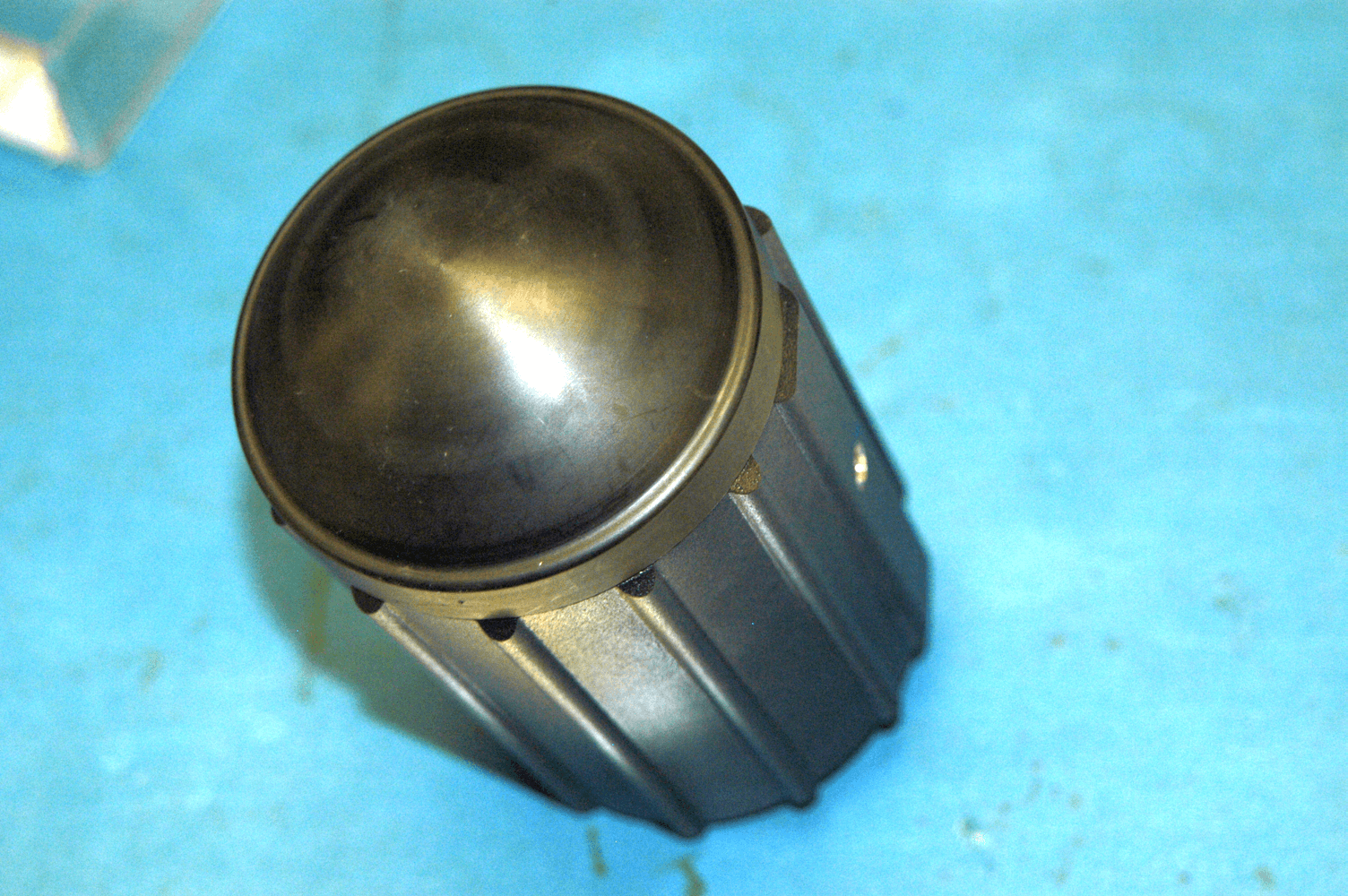
Click to zoom
Application Details
- Equipment Class
- FDS - Part 15 Field Disturbance Sensor
- Date of Grant
- Jun 14, 2011
- Application Purpose
- Original Equipment
- Date of Application
- Jun 14, 2011
- Equipment Note
- STALKER PATROL
- Frequency Range
- 24125.00000000 - 24125.00000000
- Company
- Applied Concepts Inc
- Country
- United States
Documents & Files
Document Text
Text extracted from the exhibit documents filed with the FCC. Open a document above to read the original.
Users Manual
S ® PATROL Moving Police Radar Operator 's Manual PROPRIETARY – COPYING AND REPRODUCING RESTRICTED applied concepts, inc. 2609 Technology Drive Plano, TX 75074 Phone (972) 398-3780 Fax (972) 398-3781 Toll Free Sales 1-800-STALKER Toll Free Service 1-877-STALKER [email protected] www.stalkerradar.com 011-0114-00 Rev A Regulatory Statement This device complies with Part 15 of the FCC rules. Operation is subject to the following two conditions: 1. This device may not cause harmful interference, and 2. This device must accept any interference received, including interference that may cause undesired operation. Changes or modifications not expressly approved by Applied Concepts, Inc. could void the user's authority to operate the equipment. Dear Valued Radar Customer: Thank you for choosing the S PATROL Radar System. We sincerely appreciate you purchasing the S PATROL and giving us the opportunity of serving you and your department. You will find the S PATROL to be an invaluable tool in controlling speed violators and making your streets and highways safer. Most importantly, we care about you, our customer, and want you to be completely satisfied. Our success as a company depends upon your satisfaction and experience with the S PATROL Radar. Applied Concepts, Inc. believes that the S PATROL offers more than superior performance and versatility. S PATROL is backed 100% with reliable, professional, and experienced sales and service support, ready to assist you at your request. We also offer the strongest warranty in the industry, with nationwide factory authorized repair centers to assure you of fast and efficient service. We wish you the greatest success in your speed enforcement program. Please do not hesitate to let us know if there is anything we may do to add to your product satisfaction. Thanks again! Sincerely, Applied Concepts, Inc. S PATROL is covered by one or more of the following United States Patents: 5,525,996 5,528,245 5,563,603 5,565,871 5,570,093 5,691,724 6,501,418 B1 7,411,544 In addition, other United States Patents are pending. ©2010-2011 Applied Concepts, Inc. STALKER is a registered trademark of Applied Concepts, Inc. Notice of Trade Secret. This Operator’s Manual contains trade secret and protected information that is exempted from public and/or unauthorized disclosure under various state laws, federal laws, and the definition of trade secret under the Restatement of Torts. Unauthorized or public disclosure of this Operator’s Manual may cause substantial competitive injury or harm to Applied Concepts, Inc. APPLIED CONCEPTS, INC. SPECIFICALLY ASSERTS ALL OF ITS APPLICABLE PRIVILEGES AND EXCEPTIONS TO PROTECT ITS TRADE SECRETS AND PREVENT UNAUTHORIZED PUBLICATION AND DISCLOSURE OF THE OPERATOR’S MANUAL. Standard of Care. You agree not to use this Operator’s Manual for any purpose other than in connection with police radar enforcement. You agree that the standard of care which you shall use in preventing disclosure of the Operator’s Manual to third parties shall be at least the same care that you would take in preserving the confidentiality of your own sensitive information and classified documents. You also agree to exercise reasonable care in overseeing those with access to the Operator’s Manual, and shall limit such access to only those of who have a need to know. TABLE OF CONTENTS INTRODUCTION .............................................................................................................................................................. 1 INSTALLATION ............................................................................................................................................................... 1 THEORY OF OPERATION .............................................................................................................................................. 1 DISPLAY OPERATION.................................................................................................................................................... 3 Display Front Panel ........................................................................................................................................................ 3 Display Unit Functions ................................................................................................................................................... 3 Audible Indicators .......................................................................................................................................................... 4 ERGONOMIC REMOTE CONTROL FUNCTIONS ....................................................................................................... 5 OPERATING THE STALKER PATROL ......................................................................................................................... 8 Stationary Mode Speed Measurement ............................................................................................................................ 8 Opposite Lane Moving Mode Speed Measurement ........................................................................................................ 8 Same Lane Moving Mode Speed Measurement ............................................................................................................. 9 Patrol Speed Shadowing Effect ...................................................................................................................................... 9 Low-End Patrol Speed Selection .................................................................................................................................. 10 Range (Sensitivity) Adjustment .................................................................................................................................... 10 Doppler Audio .............................................................................................................................................................. 1…
Text truncated - open the document above for the full version.
Block Diagram
HORN 2½” L E N S MIXER GUNN 24.125 GHZ PREAMP SIGNAL CONDITIONING VOLTAGE REGULATOR CIRCUIT POWER CODEC USB MICRO CLOCKS 12.288 MHZ 12.000 MHZ POWER DATA D A T A POWER CONTROL STALKER PATROL ANTENNA USB CONNECTOR FRONT ANTENNA USB 4-PIN CONN REAR ANTENNA SWITCH USB MICRO (HOST) DATA CONTROL DSP DATA SERIAL EEPROM DACAMP SPEAKER POWER/ REGULATION 570 KHZ +1.0V +3.3V POWER CONNECTOR 10~16 volts POWER SWITCH P_USB* CLOCK 16 MHZ +5.0V 188188188 XMITFRONTREARSAME REMOTE 4-PIN CONN 9-PIN CONN USB 4-PIN CONN 90 mA (typ), 280mA Max 50 mA (typ) *P_USB: switchable: 5V@100mA 7.75V @ 250mA STALKER PATROL COUNTING UNIT/DISPLAY CONTROL DATA +5.0V +5.0V +3.3V DATA 150 mA (typ), 300mA Max VSS SPI +3.3V TEMP 5~8V (VBUS)
Cover Letter(s)
• aCI applied concepts, Inc. April 26, 2011 Timco Engineering 849 N.w. State Road 45 PO Box 370 Newberry, FL 32669 Attn: Director of Certification Authority to Act as Agent FCC On our behalf, I authorize Una Kwee-Nguyen of Nemko USA, Inc., 802 N. Kealy, Lewisville, TX 75057, to act as our agent in the preparation of this application for equipment certification. I certify that submitted documents properly describe the device or system for which equipment certification is sought. I also certify that each unit manufactured, imported or marketed, as defined in Federal Communications Commission regulations will have affixed to it a label identical to that submitted for approval with this application. In signing this letter, Applicant certifies that neither the applicant nor any party to the application is not subject to a denial of Federal benefits, that include FCC benefits, pursuant to Section 5301 of the Anti-Drug Abuse Act of 1988, 21 U.S.C. § 862 because of a conviction for possession or distribution of a controlled substance. See 47 CFR 1.2002(b) for the definition of a "party" for these purposes. For instances where our authorized agent signs the application for certification on our behalf, I acknowledge that all responsibility for complying with the terms and conditions for certification, as specified by Timco Engineering still resides with Applied Concepts, Inc., 2609 Technology Drive, Plano, TX 75074. Dated this 10th Dayof~M~aYL-________ __ 20 11 Agency agreement expiration date: By: ~4t6(}/ Signature Title: Chairman March 31,2012 Alan Mead Printed On behalf of : Applied Concepts, Inc. Telephone: 972-398-3750 2609 Technology Drive Plano, Texas 75074 (972) 398-3750 FAX (972) 398-3751
ID Label/Location Info
D A B C B A DC 86 5 43 7 21 1 2 3 4 5 6 7 8 applied conc epts, inc. SIZE DWG NO REV SCALE SHEET OF TITLE LABEL, S/N PATROL COUNTING UNIT 057-1389-00 1 1 B B 2 : 1 STALKER PATROL S.N. ECXXXXXX APPLIED CONCEPTS, INC. PLANO, TX 75074 5,525,996 5,528,245 5,563,603 5,565,871 5,570,093 5,691,724 6,501,418 B1 7,218,271 7,411,544 COVERED BY THE FOLLOWING U.S. PATENTS: FCC ID: IBQACMI006 D R A W N APPROVALS / DATES THIRD ANGLE PROJECTION C H E C K .XXX = ± .005 SURFACES 63 ANGLES = ± 5° .XX = ± .01 FRACT = 1 32 TOLERANCES DIMS INCLUDE PAINTED OR PLATED SURFACE THICKNESS. ALL DIMS ARE IN INCHES. UNLESS OTHERWISE SPECIFIED A P P ' D REVISIONS REV DESCRIPTION DATE B ADD FCC ID NO., MO VE PATENT NOS. 6-6-2011 .375 .480 1.230 - .010.000 + .302 .493 1.220 R.030 4X NOTE: 1. MATERIAL TO BE .020 THICK ALUMINUM. 2. PRINT DATA AS SHOWN ON VIEW ABOVE. ALL TEXT IS AR IAL BOLD. LARGEST TEXT FOR FCC ID NUMBER IS TO BE .050 TALL. TEXT FOR COMPANY NAME AND CITY IS .045 TALL. CO MPANY NAME AND PATENT NUMBERS TO BE .035 TALL. ALL OF THIS TEXT IS TO BE SILVER (CLEAR TO SHOW ALUMINUM BASE MATERIAL) ON BLACK BACKGROUND. 3. BARCODE/SERIAL NUMBER BOX TO BE BLACK BARS/LETTE RS ON SILVER BACKGROUND (CLEAR TO SHOW ALUMINUM BASE MATERIAL). BARCODE TO BE 8 DIGIT CODE 39 WITH "EC" AS FIRST TWO DIGITS. "STALKER PATROL" AND S.N. TO BE .050 ARIAL NARROW BOLD CHARACTERS AN D CORRESPOND TO BARCODE. SERIAL NUMBER SEQUENCE TO BE SPECIFIED AT TIME OF ORDER. 4. ARTWORK TO BE APPROVED BY APPLIED CONCEPTS. BLACK BACKGROUND SILVER BACKGROUND (CLEAR TO SHOW ALUMINUM) OPENING .078 4X THRU 1.090 1.090
Operational Description
S ® PATROL SPECIFICATIONS General Specifications Type: Dual Antenna Moving/Stationary Doppler Radar Operating Frequency: 24.150 GHz (K-Band) Stability: ±100 Mhz (K-band) Power Requirements: (With 2 Antenna) 9.0 to 16.0 VDC. (currents are typical at 12VDC) XMIT ON: with maximum display brightness: 0.39A XMIT ON: with minimum display brightness: 0.29A XMIT OFF: with maximum display brightness 0.24A XMIT OFF: with minimum display brightness 0.13A Environmental: -30 to +70 C, 90% Relative Humidity Operating -40 to +85 C, non-operating Display: Sunlight viewable WHITE on BLACK Liquid Crystal Display (LCD) panel with seven icons and triple 3-digit windows for target, lock/fast and patrol windows. LCD has HEA film and 9:00 polarization. Mechanical: Counting unit Wt. – 1.1 lbs (0.498 kg) 1.68" Height, 3.59" Depth, and 5.52" Width (4.26 cm Height, 10.0 cm Depth, and 14.0 cm Width) Antenna Wt. -1.2 lbs. (0.544 kg) 2.89" Dia. X 5.26" (includes connector) (7.3 cn Dia. X 13.3 cm) Remote Weight - 0.4 lb. (0.181 kg) 1.25" Height, 6.50" Length, and 2.25" Width ((2.0 cm Height, 16.5 cm length and 6.8 cm Width) Accuracy: ±1 mph (or kph) stationary ±1mph (or kph) moving, when using Vehicle Speed Sensor ±2mph (or kph) moving, when Vehicle Speed Sensor is not used Automatic Self-Test: Performed every 15 minutes while transmitting Stationary Speed Range: 10 mph to 210 mph Standard (16 to 337 Km/h) 2 mph to 210 mph (3 to 337 Km/h(set-up menu selectable) Moving Speed Range: Patrol speed - Selectable with P.S. 5/20 key: 5 in patrol window for acquisition of 5 to 90 mph (8 to 144 Km/h) 10 in patrol window for acquisition of 10 to 90 mph(16 to 144 Km/h) 20 in patrol window for acquisition of 20 to 90 mph (32 to 144 Km/h) Patrol speed, once acquired, will track to 150 mph (241 Km/h) Same lane patrol speed must be greater than 19 mph (30 Km/h) Opposite lane target speed - 210 mph (337 Km/h)Max closing For 5 mph (8 Km/h)patrol speed: 20 mph to 205 mph (32 to 329 Km/h) For 70 mph (112 Km/h)patrol speed: 35 mph to 140 mph(56 to 225 Km/h). Same lane target speed - Related to patrol speed: ±80% of patrol speed to within 5 mph (8 Km/h) of patrol speed i.e. For 50 mph (89 Km/h): 15 → 44 mph (24→ 70 Km/h)and 55 → 85 mph (88→ 136 Km/h) Faster Speed - Same speed range as opposite lane speed Microwave Specifications Antenna: Conical horn with corrective lens Polarization: Circular 3 db Beam width: 13° nominal, 15° maximum Microwave Source: Gunn-Effect diode Receiver Type: Direct Conversion Homodyne using low-noise Schottky barrier mixer diode Power Output: 8 mw min (K-band) 12 mw nom (K-band) 20 mw max (K-band) Power Density: 1 mw/cm 2 maximum at 5 cm from lens Display Messages PASS: PASS spelled out in display with a 4-beep “happy” tone indicates the unit has just passed self-test. FAIL: FAIL spelled out in display with a 15-beep tone indicates a circuit malfunction has been detected, in which case speed readings are inhibited. Remove the unit from service and repair. FAIL will remain on the display until reset by being powered off. SEn 1, SEn 2, SEn 3 or SEn 4: SEn 1 thru SEn 4 is used to indicate the current range (sensitivity) setting . SEn 1 is minimum; SEn 4 is maximum. Opposite lane sensitivity is independent of same lane sensitivity. They are separately set. 5, 10 or 20: 5, 10 or 20 spelled out in the patrol window indicates the low-end patrol speed is set to either 5, 10 or 20 mph (8,16 or 32 Km/h) Aud 0 .. Aud 9: Aud 0 thru Aud 9 spelled out on the display unit indicates the current speaker volume setting. Aud 0 is off; Aud 9 is loudest. bri 1, bri 2 bri 3, bri 4, bri 5, or bri 6: Used to indicate display brightness. bri 1 is the dimmest; bri 6 is the brightest. Hot: The display flashes Hot and powers down when the internal temperature exceeds specifications.Automatically resumes operating when the temperature drops. Lo V: A Lo V message indicates the input voltage is too low. Operation is inhibited while the Lo V message is displayed but normal operation will resume automatically when the input voltage is restored. All other speed windows will be blanked. Remote Control Functions SAME/OPPOSITE: The SAME/OPPOSITE key is used to alternate between same lane moving mode and opposite lane moving mode. The SAME icon toggles on and off to indicate same lane mode. LOCK/RELEASE: The LOCK/RELEASE key is a dual function key. This key alternates between the lock and the release functions. LOCK is used to transfer the contents of the target window to the lock window. RELEASE clears the locked contents of the lock window and the patrol window. During lock, the patrol window will lock the present patrol speed and the LOCK icon will light. The target window and Doppler audio remain active after locking. ANT: Used to switch between the front and rear antenna. The FRONT or REAR icon will light. A 1-beep tone corresponds to the front antenna while a 2-beep tone corresponds to the rear antenna. The counting unit can sense the presence or absence of either antenna. XMIT/HOLD: Toggles between xmit and hold (standby). The XMIT icon will light. MOVING/STATIONARY: Toggles between moving and stationary modes. FASTEST: Used to select fastest mode. A high pitched tone indicates that fastest mode is selected. Any power off event will reset the fastest mode to OFF. SLOWER: The SLOWER key is used to toggle between fast target same lane mode and slow target same lane mode. The SLOW icon is on for a slower target. SEn : Used to adjust the range (sensitivity) at any time. Maximum sensitivity is SEn 4; minimum sensitivity is SEn 1. Opposite lane sensitivity is independent of same lane sensitivity. They are separately set. SQL: Toggles the squelch override off and on. In the normal (off) position, audio will only be heard when a target is being tracked. P.S. 5/20: Used to select a low-end patrol speed of either 5 mph, 10 mph or 20 mph. For example: 5 in patrol window for speed of 5 (8 Km/h) 20 in patrol window for speed of 20 (32 Km/h) TEST: Performs …
Text truncated - open the document above for the full version.
Operational Description
Technical Description and Theory of Operation for Applied Concepts’ Stalker Patrol Police Radar Pg. 1 This equipment consists of the following modules: 1. Counting Unit/Display 2. One or two Antennas 3. Infrared Remote Control 4. Power Cable 5. One or two Antenna Cables Counting Unit/Display The Counting Unit/Display contains two circuit boards. Please see schematics 002-5311-00 for the main board and 002-5316-00 for the display board. Main Board Twelve volt automotive electrical power is supplied to the unit through the cigarette plug Power Cable to pin 1 of J1 on the main circuit board, and pin 2 of J1 is the ground return. EMI filtering is provided by C33, C34 and FB1 and over current protection is provided by thermal fuse F1. Q11 provides reverse polarity protection while maintaining a low voltage drop in normal operation and Z1 is a transient suppressor that prevents high voltage “spikes” on the automotive power from reaching the electronics. This filtered and conditioned power is supplied to the rest of the unit as signal +12USW. The main board provides three switch-mode power supplies developing 3.3 volts and 5 volts for operation of the main board and display, and a voltage that switches between 5 volts and 8 volts for operation of the antennas. The 3.3 volt regulator is U6 on the main board. This is a buck-mode regulator operating at 570 KHz. The output of this regulator is supplied to linear regulator U7 on the main board that supplies 1 volt to operate the DSP U12 core. This 1 volt regulator provides regulated output whenever 3.3 volts is present. The 5 volt regulator is U3 on the main board. This is a buck-mode regulator operating at 570 KHz. The antenna regulator is U5 on the main board. This is a buck-mode regulator operating at 570 KHz, and switching between 5 volts and 8 volts is accomplished by transistor Q4 under control of the auxiliary processor U15. All three voltage regulators share a common enable signal provided by power control circuitry Q5, Q6, Q8 and Q10 on the main circuit board. The front-panel POWER switch switches signal PWDN to ground when the switch is pressed. When this signal is switched to ground, transistors Q6 and Q8 are turned on. The drain of Q6 pulls the enable signal for the three regulators high and starts up the system. The drain of Q8 provides signal PDWN_RQST to the auxiliary processor U15 to signal that the POWER switch has been pressed. The auxiliary processor U15 provides signal PSET to control transistor Q10 which also pulls the enable signal for the three Technical Description and Theory of Operation for Applied Concepts’ Stalker Patrol Police Radar Pg. 2 regulators high so that once started up, the auxiliary processor can keep the regulators operating until a power off command is received from the POWER switch. The auxiliary processor U15 provides overall power control for the system, handles USB communication and power control for the antenna(s) and provides analog to digital converters to allow monitoring of input power voltage through voltage divider R10 and R11 and clamp diodes D16 and D17, and internal temperature sensed by sensor U1. This processor and the Digital Signal Processor (DSP) are both clocked by a crystal oscillator X1 at 16 MHz. This signal is internally multiplied by 20 in the auxiliary processor to obtain a clock at 320 MHz, and then divided down to 80 MHz for the processor clock and 48 MHz for the USB clock. On initial power up, the auxiliary processor sets the antenna power voltage to 5 volts in compliance with USB standards. This provides sufficient power for the USB interface in the antenna to operate. The processor then attempts to establish a USB link with the antenna, and once the presence of a Stalker Patrol antenna is confirmed the antenna power is switched to 8 volts to provide a higher voltage needed to operate the transmitter. This scheme prevents applying excessive voltage in the event a USB device other than a Stalker Patrol antenna is plugged into the USB connector(s). At any point in time, only one antenna is powered on. Antenna power switching is handled by transistors Q2, Q3, Q7 and Q8 under control of the auxiliary processor by signals ANT_FRONT and ANT_REAR. The USB data path is also switched between antennas by U8 and U26 under control of the auxiliary processor by signal ANT_FRONT. D9 and D10 are transient suppressors to prevent electrostatic damage to the USB drivers and receivers. In normal operation, the active antenna will sample data at a rate of 32 KHz. At 2 millisecond intervals, the antenna will transmit the last 64 samples collected along with system information in one packet containing 100 sixteen bit words (1600 total data bits) to the counting unit at the USB bit rate of 48 MHz. The auxiliary processor receives this data and passes it along to the DSP U12 over a Serial Peripheral Interface (SPI) using signals ANT_BCLK, ANT_SDATAI and ANT_FS. Clocking for this data is such that the 1600 bits of data plus analog-to-digital converter data is transmitted in a little less than 2 ms to provide dead time for synchronization. Control information is also sent from the DSP to the auxiliary processor during each 2 ms interval using signal ANT_SDATAO and the ANT_BCLK and ANT_FS signals shared with the receive channel. This data is then transmitted over the bidirectional USB interface to the antenna by the auxiliary processor. Connector J30 provides an interface to the auxiliary processor to permit programming the internal flash memory of the processor. This connector is not used in normal operation of the radar. The DSP U12 is clocked by the same 16 MHz clock as the auxiliary processor. This clock is internally multiplied by 25 to obtain 400 MHz and then divided by two to obtain a main processor clock at 200 MHz. The DSP receives the antenna data transmitted over the SPI interface and performs the primary signal processing functions of the radar. The DSP also drives the LCD display, receives and…
Text truncated - open the document above for the full version.
Test Report
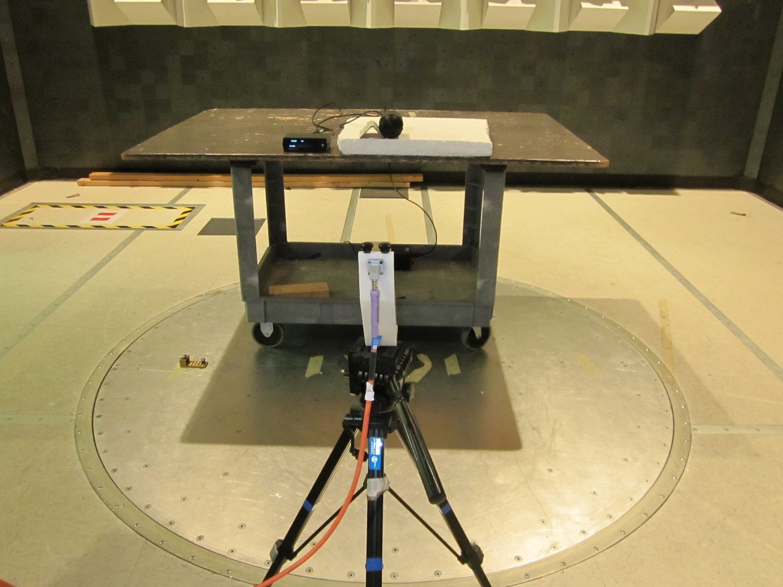
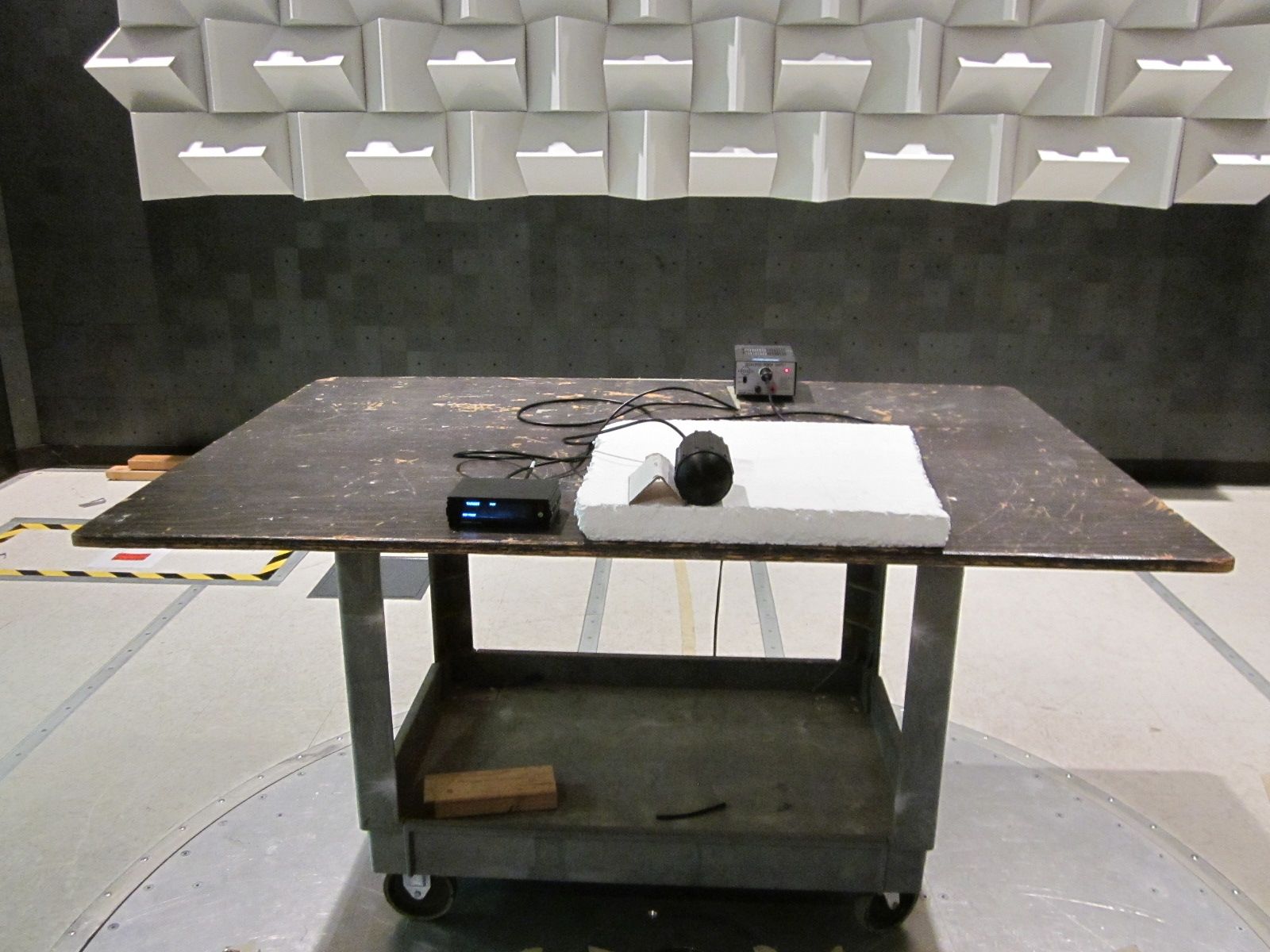
Nemko Test Report: 1023276RUS1 Applicant: Applied Concepts, Inc. 2609 Technology Drive Plano, Texas 75074 USA Equipment Under Test: Stalker Patrol (E.U.T.) FCC ID: IBQACMI006 In Accordance With: FCC Part 15, Subpart C For Operation Within The Bands 902-928 MHz, 2435-2465 MHz, 5785-5815 MHz, 10500-10550 MHz, 24075-24175 MHz Intentional Radiators Used As Field Disturbance Sensors Excluding Perimeter Protection Systems Tested By: Nemko USA, Inc. 802 N. Kealy Lewisville, Texas 75057-3136 TESTED BY: DATE: 13 April 2011 David Light, Senior Wireless Engineer APPROVED BY: DATE: 2 May 2011 Number of Pages: 15 Nemko USA, Inc. FCC PART 15, SUBPART C Field Disturbance Sensors EQUIPMENT: Stalker Patrol Test Report No.: 1023276RUS1 Page 2 of 15 Table of Contents SECTION 1. SUMMARY OF TEST RESULTS 3 SECTION 2. EQUIPMENT UNDER TEST (E.U.T.) 5 SECTION 3. FIELD STRENGTH OF EMISSIONS 7 SECTION 4. BLOCK DIAGRAMS 9 SECTION 5. TEST EQUIPMENT LIST 10 ANNEX A - RESTRICTED BANDS 11 ANNEX B - RADIATED EMISSION LIMITS 13 Nemko USA, Inc. FCC PART 15, SUBPART C Field Disturbance Sensors EQUIPMENT: Stalker Patrol Test Report No.: 1023276RUS1 Page 3 of 15 Section 1. Summary of Test Results Manufacturer: Applied Concepts, Inc. Model No.: Stalker Patrol Serial No.: EC001000 General: All measurements are traceable to national standards. These tests were conducted on a sample of the equipment for the purpose of demonstrating compliance with Part 15, Subpart C, Paragraph 15.245 for Field Disturbance Sensors. Radiated tests were conducted is accordance with ANSI C63.4- 2003. Radiated emissions are made on an open area test site. A description of the test facility is on file with the FCC. New Submission Production Unit Class II Permissive Change Pre-Production Unit THIS TEST REPORT RELATES ONLY TO THE ITEM(S) TESTED. THE FOLLOWING DEVIATIONS FROM, ADDITIONS TO, OR EXCLUSIONS FROM THE TEST SPECIFICATIONS HAVE BEEN MADE. See “ Summary of Test Data”. Nemko USA, Inc. authorizes the above named company to reproduce this report provided it is reproduced in its entirety, for use by the company’s employees only. This report must not be used to claim product certification, approval, or endorsement by NVLAP, NIST, or any agency of the Federal Government. Nemko USA, Inc. is a NVLAP accredited laboratory. Any use which a third party makes of this report, or any reliance on or decisions to be made based on it, are the responsibility of such third parties. Nemko USA, Inc. accepts no responsibility for damages, if any, suffered by any third party as a result of decisions made or actions based on this report. This report applies only to the items tested. Nemko USA, Inc. FCC PART 15, SUBPART C Field Disturbance Sensors EQUIPMENT: Stalker Patrol Test Report No.: 1023276RUS1 Page 4 of 15 Summary Of Test Data NAME OF TEST PARA. NO. RESULT Powerline Conducted Emissions 15.207(a) NA Field Strength of Emissions 15.245(b) Complies Footnotes: 1) This device is battery powered. Nemko USA, Inc. FCC PART 15, SUBPART C Field Disturbance Sensors EQUIPMENT: Stalker Patrol Test Report No.: 1023276RUS1 Page 5 of 15 Section 2. Equipment Under Test (E.U.T.) General Equipment Information Frequency Band (MHz): 24075 to 24175 Operating Frequency of Test Sample: 24125 MHz Channel Spacing: NA User Frequency Adjustment: None Modulation: None(the rf signal is not modulated or pulsed) Nemko USA, Inc. FCC PART 15, SUBPART C Field Disturbance Sensors EQUIPMENT: Stalker Patrol Test Report No.: 1023276RUS1 Page 6 of 15 Description of E.U.T. Law enforcement radar for speed detection. Modifications Incorporated in E.U.T. The EUT has not been modified from what is described by the brand name and unique type identification stated above. Nemko USA, Inc. FCC PART 15, SUBPART C Field Disturbance Sensors EQUIPMENT: Stalker Patrol Test Report No.: 1023276RUS1 Page 7 of 15 Section 3. Field Strength of Emissions NAME OF TEST: Field Strength of Emissions PARA. NO.: 15.245(b) TESTED BY: David Light DATE: 12 April 2011 Minimum Standard: The field strength of emissions from intentional radiators operated within these frequency bands shall comply with the following: Fundamental frequency (MHz) Field strength of fundamental (millivolts/meter) Field strength of harmonics (millivolts/meter) 902–928 500 1.6 2435–2465 500 1.6 5785–5815 500 1.6 10500–10550 2500 25.0 24075–24175 2500 25.0 Test Results: Complies. The worst-case emission level is 134.3 dBV/m @ 1m at 24.1 GHz. This is 3.2 dB below the specification limit. Test Data: See attached table. Above 1 GHz a spectrum analyzer and low noise amplifier are used to measure emission levels. The spectrum analyzer resolution bandwidth was set to 1 MHz and video bandwidth was 3 MHz. In the case of handheld equipment, the E.U.T. is rotated in three planes to obtain worst- case results. Nemko USA, Inc. FCC PART 15, SUBPART C Field Disturbance Sensors EQUIPMENT: Stalker Patrol Test Report No.: 1023276RUS1 Page 8 of 15 Test Data - Radiated Emissions The spectrum was searched from 30 MHz to 100 GHz. All emissions within 20 dB of the specification limit are reported. The device is battery powered (automotive). In lieu of testing with a new battery, it was tested using a 12 Vdc regulated power supply. Meas.AntAtten.MeterAntennaPatRCorrectedSpecCR/SPas FreqPolReadinFacto rLosGaiReadinlimitDiffFai (GHz)(H/V(dB(dBuV(dB(dB(dB(dBuV/m (dBuV/m(dB)Unc.Commen 24.1 V090.740.43.20.0134.3137.5-3.2Pass1 meter 24.1 H090.540.43.20.0134.1137.5-3.4Pass1 meter 48.2 V05140.50.00.091.597.5-6.0Pass1 meter 48.2 H04640.50.00.086.598.5-12.0Pass1 meter 72.3 V05543.70.00.098.7111.5-12.8Pass20 cm 72.3 H05543.70.00.098.7112.5-13.8Pass20 cm 96.4 V05746.40.00.0103.4111.5-8.1Pass20 cm 96.4 H05746.40.00.0103.4112.5-9.1Pass20 cm Nemko USA, Inc. FCC PART 15, SUBPART C Field Disturbance Sensors EQUIPMENT: Stalker Patrol Test Report No.: 1023276RUS1 Page 9 of 15 Section 4. Block Diagrams Outdoor Test Site For Radiated Emissions Indoor Measurement Setup for Emissions Above 10 GHz E.U.T. S…
Text truncated - open the document above for the full version.
Contact Information
Applicant
Alan B Mead(CEO)
Test Firm
Nemko Dallas, Inc.Mike Cantwell
Technical Specifications
| # | Rule Parts | Frequency Range | Power Output |
|---|---|---|---|
| 1 | 15.245 | 24.13 GHz - 24.13 GHz | - |
Other Applications from Applied Concepts Inc
IBQACMI005
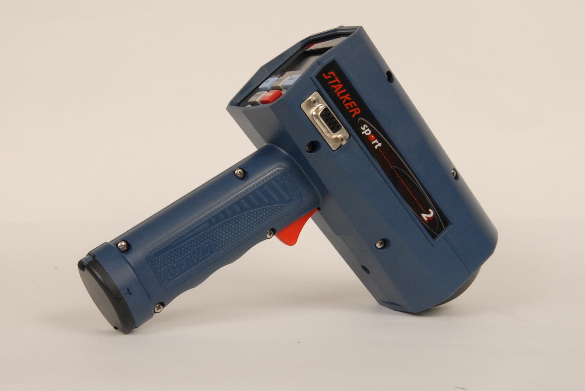
Sep 27, 2007Speed SensorRadar
Equipment Class
FDS - Part 15 Field Disturbance SensorIBQACMI003
May 29, 1995TNB - Licensed Non-Broadcast Station Transmitter
Equipment Class
TNB - Licensed Non-Broadcast Station TransmitterIBQACMI004
May 29, 1995TNB - Licensed Non-Broadcast Station Transmitter
Equipment Class
TNB - Licensed Non-Broadcast Station Transmitter