IHDT56FV1Mobile Cellular/ PCS GSM Transceiver Module
Motorola Mobility LLC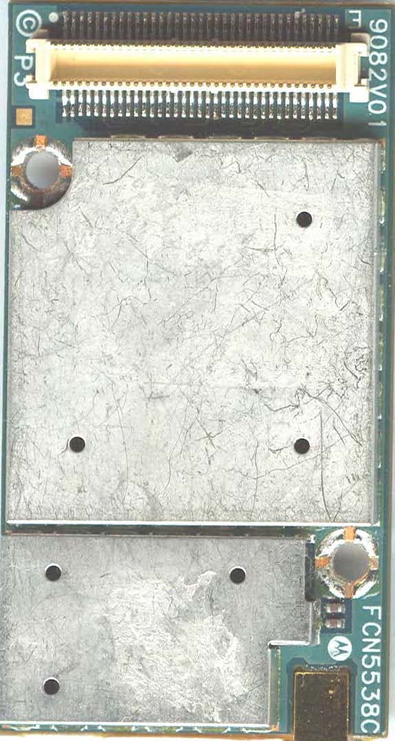
Click to zoom
Application Details
- Equipment Class
- PCB - PCS Licensed Transmitter
- Date of Grant
- Dec 20, 2005
- Application Purpose
- Original Equipment
- Date of Application
- Dec 20, 2005
- Equipment Note
- Mobile Cellular/ PCS GSM Transceiver Module
- Frequency Range
- 1850.20000000 - 1909.80000000
- Company
- Motorola Mobility LLC
- Country
- United States
Documents & Files
Document Text
Text extracted from the exhibit documents filed with the FCC. Open a document above to read the original.
Users Manual
Applicant: Motorola Inc. FCC ID:IHDT56FV1 Exhibit 8 Page 1 of 8 G24 Developer Guide Table of Contents GENERAL.........................................................................................................................2 GENERAL DESCRIPTION ............................................................................................ 3 GETTING STARTED ...................................................................................................... 5 GENERAL PURPOSE SWITCHES............................................................................... 6 EMU BUS – UID PIN........................................................................................................ 6 A/D OPERATION............................................................................................................... 6 GPIO ............................................................................................................................... 7 AUDIO.............................................................................................................................. 7 SPI................................................................................................................................... 7 GENERAL POSITIONS........................................................................................................ 8 Applicant: Motorola Inc. FCC ID:IHDT56FV1 Exhibit 8 Page 2 of 8 General This document content describes the operation of the G24 Evaluation board (EVB) P1. The G24 EVB supports two G24 versions: OEM, and fixed mobile. For the fixed mobile a secondary board is mounted on EVB (“Piggy Board”, using connector P50). The follow PDF file contains EVB schematic and layout (all References are searchable) 8899_schem_place_s earch.pdf Applicant: Motorola Inc. FCC ID:IHDT56FV1 Exhibit 8 Page 3 of 8 General Description 1) P210 - Battery socket connector for a Lithium-ion battery. Note: set P203 jumper to battery, line 9. 2) J200, J201 – Lab Power Supply jacks. Note: set P203 jumper to P.S, line 9. 3) J230 – Wall Adapter connector. Note: set P203 jumper to adapter, line 9. 4) S200, D200 – Main power switch, and led indicator. 5) J380- EMU (Mini-USB) socket. 6) J300 – RS232-1, G24 UART 1. 7) J330 – RS232-2, G24 UART 2. 8) J350 – RS232-SPI, G24 SPI bus debugger (enabled with line 14). 9) P203 – Selecting power supply Source. Connect jumper to select 1 of 3 options (Wall Adapter, lab power supply, or battery). Note: G24 EVB shall not work if not connecting this jumper. 10) P2 – G24EVB on board Antenna. 11) S110, D701 – G24 On/Off Switch and led indicator. 12) S160, S161, S171, S170 – General switches for testing. 10 22 G24 EVB – Top View (Without 2 nd Keypad board) 8 11 7 6 5 4 3 21 9 19 21 18 17 16 15 13 12 10 20 14 23 24 22 Applicant: Motorola Inc. FCC ID:IHDT56FV1 Exhibit 8 Page 4 of 8 13) J100 – SIM Card socket. 14) S140, S120, S121 - General switches for testing. 15) J430 – Speaker Jack connector. 16) J460 – Microphone Jack connector. 17) J440 – Headset Jack connector. 18) J480 – Alert speaker Jack connector. 19) P50- 40 pin header for 2 nd Keypad board (“Piggy Board”). 20) S100, S141 - General switches for testing. 21) P100 – 70-pin header. This header spreads G24 70 pin connector (P1) for signal measuring. 22) CLI Display. 23) P1 – 70-pin connector for G24. 24) P201, P200 – Secondary power jumpers. G24EVB main power is divided to 2 roots, 1 st to EVB, and 2 nd to G24 unit. Applicant: Motorola Inc. FCC ID:IHDT56FV1 Exhibit 8 Page 5 of 8 Getting Started - Select power supply source (Wall Adapter, lab power supply, or battery), and connect it to suitable jack (either line 1, 2, or 3). - Set P203 jumper (line 9) according to your main power source selection. - Make sure that P201, P200 jumpers are connected (line 24). - Mount G24 on G24EVB using P1 connector (line 23). - Connect G24 Antenna to P2 (line 10) - Optional - Turn On main power switch S200 (line 4), led indicator D200 is On. - Press S110 On/Off switch (line 11) for turning On G24 unit. Applicant: Motorola Inc. FCC ID:IHDT56FV1 Exhibit 8 Page 6 of 8 General Purpose Switches The G24 contains General Purpose Switches for simulating testing states. For detail schematics see PDF file in General Section (at the beginning of this doc). EMU Bus – UID pin S170, S171 and S160 1 st switch are used to simulate UID pin of the G24 EMU bus. The default position (as shown in figure) is that UID pin is not connected. - Switching On (left) S160 UID position shall enable S170, S171. - Select Only one position from S170, S171 according to EMU spec. A/D operation G24 has 3 General A/D. G24 can simulate analog voltages vary from 0.1V-1.7V. - Set S161 switch position to desired voltage level. - Enable desired ADC (S160). Line 12 Applicant: Motorola Inc. FCC ID:IHDT56FV1 Exhibit 8 Page 7 of 8 GPIO G24 has 8 General Purpose I/O. S120, S121 along with GPIO led indicators simulate GPIO state. G24 has internal pull-ups. - Switch left position – GPIO line is disconnected. - Switch right position – GPIO line is shorted to ground. Audio S140 Audio position selects the Audio path of G24. - Switch left position – Analog Audio path (Using G24 internal vocoder). - Switch right position – digital Audio path (Using G24EVB on board vocoder). SPI Enable SPI logger (line 8) Line 14 Applicant: Motorola Inc. FCC ID:IHDT56FV1 Exhibit 8 Page 8 of 8 General Positions - *, # - Simulating *, and # phone keys. - Option – connects between WKUPO_N & WKUPI_N (Pins 16 & 26) in G24 70 pin. - WAKEUP - connects WKUPI_N (pin 16) to ground - ADPTR – connects Wall Adapter voltage to USB VBUS. - CHRG – connects between USB VBUS to G24 Ignition. - IGN – connect G24 Ignition to G24EVB voltage. - DP-DN – connect between G24 USB DP & USB DN signals Line 20 G24 EVB – Top View (With Keypad board)
Attestation Statements
APPLICANT: MOTOROLA, INC. FCC ID: IHDT56FV1 SPECIFICATION COMPLIANCE STATEMENT Engineer-in-Charge Equipment Authorization Branch Federal Communications Commission The transceiver type IHDT56FV1 has been tested in accordance with the requirements contained in the appropriate Commission regulations. To the best of my knowledge, these tests were performed using measurement procedures consistent with industry or Commission standards and demonstrate that this equipment complies with the appropriate standards. Each unit manufactured imported or marketed, will conform to the sample tested within the variations that can be expected due to quantity production and testing on a statistical basis. I further certify that the necessary measurements were made at Hermon Laboratories Ltd. P.O. Box 23, Binyamina 30500, Israel. Menashe Cohen Engineering HW Manager OEM embedded modules Design Center Eli Zakuto Engineering Manager OEM embedded modules Design Center DATE: July 7 th , 2005 1 Exhibit 2A APPLICANT: MOTOROLA, INC. FCC ID: IHDT56FV1 STATEMENT OF CERTIFICATION The technical data supplied with this application, having been taken under my supervision is hereby duty certified. SIGNATURE: (signed) Menashe Cohen NAME: Menashe Cohen DATE: July 7 th , 2005 POSITION: Engineering HW Manager I hereby certify that the above application was prepared under my direction and that to the best of my knowledge and belief, the facts set forth in the application and accompanying technical data are true and correct: SIGNATURE: (signed) Eli Zakuto NAME: Eli Zakuto DATE: July 7 th , 2005 POSITION: Engineering Manager 2 Exhibit 2B
Cover Letter(s)
APPLICANT: MOTOROLA FCC ID: IHDT56FV1 September 12,2005 CONFIDENTIALITY REQUEST CONTAINED WITHIN Federal Communications Commission Authorization and Evaluation Division 7435 Oakland Mills Road Columbia, Maryland 21046 Re: Application for Cellular/PCS Transceiver Certification Gentlemen: Application: Motorola, Inc., Mobile Device Business, 600 N. U.S. Highway 45, Libertyville, Illinois 60048-1286 herein submits: Application for Equipment Authorization for Certification of a Cellular Transceiver, FCC ID: IHDT56FV1. Motorola is also the manufacturer of this equipment. Confidentiality: Pursuant to Section 0.459 of the Commission's rules (CFR 47), Motorola requests confidentiality for portions of the material contained in this application and that the identified material be withheld from public inspection following the grant of this authorization. This material contains Motorola's trade secrets and confidential information that Motorola does not customarily release to the public and which is otherwise not generally available to the public. Confidentiality is requested for the following exhibits: • Exhibit 4 Block Diagrams • Exhibit 5 Schematics • Exhibit 12 Operational Description Description: This equipment is an OEM module (similar to FCC ID: IHDT56DB1), and can transfer data or voice over cellular and PCS networks. It has the capability to operate in 850 MHz & 1900 MHz GSM Bands. Contact Information: Please contact me by telephone at (847) 523-6167, or by e-mail ([email protected]) , if there are questions or additional information needed concerning this filing. Regards, Andrew J. Bachler FCC Liaison Mobile Devices 600 N. U.S. Highway 45 Libertyville, IL 60048-5343 Exhibit 13
Cover Letter(s)
Date: December 19, 2005 Subject: Request for additional information regarding FCC ID: IHDT56FV1 (Portable PCS GSM transceiver) Reference: Application Received: 9/28/2005 Correspondence Reference Number: 150928A.IHD Confirmation Number: 1509280474 Date of Original Email: 12/19/05 Prepared by: Andrew Bachler, Principal Staff Engineer Motorola Mobile Device Business Libertyville, Illinois Questions and responses follow: 1. This application is missing the 20cm statement in the Users Manual. RESPONSE: The following statement will be added to the user’s manual. User Operation Do not operate your telephone when a person is within 8 inches (20 centimeters) of the antenna. A person or object within 8 inches (20 centimeters) of the antenna could impair call quality and may cause the phone to operate at a higher power level than necessary and expose that person to RF energy in excess of that established by the FCC RF Exposure Guidelines. IMPORTANT The telephone must be installed in a manner that provides a minimum separation distance of 20 cm or more between the antenna and persons to satisfy FCC RF exposure requirements for mobile transmitting devices. 2. FYI: There is a typo on page 6 of the EMC report stating that the device is portable RESPONSE: Please reference corrected EMC report Exhibit 6A submitted on 12-20-05. 3. FYI: There is a typo on page 18 of the EMC report, stating that the output power is 30.03dBm for the 850MHz band. RESPONSE: Please reference corrected EMC report Exhibit 6A submitted on 12-20-05. 1
External Photos
APPLICANT: MOTOROLA, INC. FCC ID: IHDT56FV1 Front View Rear View 1 EXHIBIT 3
ID Label/Location Info
APPLICANT: MOTOROLA INC. FCC ID: IHDT56FV1 FCC IDENTIFICATION (NAMEPLATE) INFORMATION FCC ID: IHDT56FV1 The FCC label shown is representative of the label that will appear on the radio when in production. It will be placed on the outside of the equipment as shown in Exhibit 3. Other information may also be included on this label. EXHIBIT 1
Internal Photos
APPLICANT: MOTOROLA INC. FCC ID: IHDT56FV1 Front View (Shields Removed) Rear View (Shields Removed) 1 EXHIBIT 9 APPLICANT: MOTOROLA INC. FCC ID: IHDT56FV1 Front View (With Shield) Rear View (With Shield) 2 EXHIBIT 9
RF Exposure Info
1 1 August 31, 2005 SAR Test Report for Motorola Mobile Cellular Phone FCC ID IHDT56FV1. Prepared by: Steven Hauswirth, Principal Staff Engineer Motorola Personal Communications Sector Product Safety & Compliance Laboratory Libertyville, Illinois The Motorola Personal Communications Sector Product Safety & Compliance Laboratory has evaluated the mobile cellular phone, FCC ID IHDT56FV1, for the need to conduct SAR evaluation. Due to the design and installation of this product, it is not possible to conduct SAR evaluation. This is because Motorola neither manufactures or supplies the antenna(s) that will be used in the installation of this product. Therefore, this product will be evaluated as a mobile device per 47 CFR §1.1310 titled “Radiofrequency radiation exposure limits”, generally referred to as MPE limits. In 47 CFR § 2.1091, paragraph (b) defines a mobile device as “a transmitting device designed to be used in other than fixed locations and to generally be used in such a way that a separation distance of at least 20 centimeters is normally maintained between the transmitter’s radiating structure(s) and the body of the user or nearby persons.” This product is intended to be installed into a vehicle such that the unit is physically secured at one location. In the installation guide supplied with the product, Motorola has made the following statement: “IMPORTANT: To meet the FCC’s RF Exposure Guidelines, the antenna should be installed so there is at least 20 cm of separation between the body of the user and nearby persons and the antenna”. Based on the installation of the transceiver and the antenna, the transmitters radiating structure is more than 20 centimeters from the user. Thus, this product is a “mobile device” as defined in section § 2.1091 paragraph (b). Table 1 (B) of 47 CFR §1.1310 lists the limits for MPE for the General Population. Since the mobile cellular phone operates in the 800MHz cellular band and 1900MHz PCS band, the listed limit of f/1500 applies. The lowest transmit frequency for this product is 824.04 MHz, resulting in a MPE limit of 0.549 mW/cm 2 . Since Motorola neither manufactures or supplies the antenna(s) that will be used in the installation of this product, it is not possible to measure the MPE of the actual device as it is installed per the installation manual. Therefore a calculation of MPE will be described in the next paragraph. The MPE of a radiating structure can be calculated by knowing the transmit EIRP and the distance at which MPE is being calculated. In this case MPE will be calculated at 20 cm, which is the minimum separation between the body of the user and nearby persons and the antenna. The maximum sourced based time-averaged transmit power for this product is 0.50 Watts in the GPRS 850 mode and 0.25 Watts in the GPRS 1900 mode. At 824.04MHz, when installed using a combined cable loss and antenna gain of a maximum of 6.9 dBi the maximum ERP will be less than 1.5 Watts. The model used for calculating power density in OET Bulletin 65, Edition 97-01, is the spherical model. Using this spherical model, 0.48mW/cm2 is achieved at a distance of 20cm from the antenna at 824.04MHz. This is below the limit of 0.55 mW/cm2. For GSM 1900, the power density is 0.24mW/cm2, which is below the limit of 1.00 mW/cm2. Therefore, by requiring the user and nearby persons to remain at least 20cm from the antenna, the MPE is not exceeded.
Test Report
Hermon Laboratories Ltd. P.O.Box 23, Binyamina 30500, Israel Tel. +972 4628 8001 Fax. +972 4628 8277 E-mail: [email protected] Page 1 of 153 Report ID: MOTRAD_FCC.16719_rev1.doc Date of Issue: November 2005 Electrical TEST REPORT ACCORDING TO: FCC parts 22, 24 and part 15 subpart B FOR: Motorola Communications Israel Ltd. QuadBand GSM module 850/1900 MHz Model:G24 FCC ID:IHDT56FV1 This report is in conformity with ISO/ IEC 17025. The A2LA logo endorsement applies only to the test methods and the standards that are listed in the scope of Hermon Laboratories accreditation. The test results relate only to the items tested. This test report shall not be reproduced in any form except in full with the written approval of Hermon Laboratories Ltd. Report ID: MOTRAD_FCC.16719_rev1.doc Date of Issue: November 2005 Page 2 of 153 Table of contents 1 Applicant information..................................................................................................................................................... 3 2 Equipment under test attributes .................................................................................................................................... 3 3 Manufacturer information .............................................................................................................................................. 3 4 Test details.................................................................................................................................................................... 3 5 Tests summary.............................................................................................................................................................. 4 6 EUT description............................................................................................................................................................. 5 6.1 General information....................................................................................................................................................... 5 6.2 Support and test equipment .......................................................................................................................................... 5 6.3 Operating frequencies ................................................................................................................................................... 5 6.4 Changes made in the EUT ............................................................................................................................................ 5 6.5 Transmitter characteristics ............................................................................................................................................ 6 7 Transmitter tests according to 47CFR part 22 requirements......................................................................................... 7 7.1 Peak output power ........................................................................................................................................................ 7 7.2 Occupied bandwidth test ............................................................................................................................................. 10 7.3 Spurious emissions at RF antenna connector test ...................................................................................................... 17 7.4 Field strength of spurious emissions ........................................................................................................................... 42 7.5 Frequency stability test................................................................................................................................................ 60 8 Transmitter tests according to 47CFR part 24 requirements....................................................................................... 63 8.1 Peak output power ...................................................................................................................................................... 63 8.2 Occupied bandwidth test ............................................................................................................................................. 66 8.3 Spurious emissions at RF antenna connector test ...................................................................................................... 73 8.4 Field strength of spurious emissions ......................................................................................................................... 101 8.5 Frequency stability test.............................................................................................................................................. 122 9 Unintentional radiation tests according to 47CFR part 15 subpart B requirements ................................................... 125 9.1 Conducted emissions ................................................................................................................................................ 125 9.2 Radiated emissions ................................................................................................................................................... 129 10 APPENDIX A Test equipment and ancillaries used for tests..................................................................................... 139 11 APPENDIX B Measurement uncertainties................................................................................................................. 141 12 APPENDIX C Test facility description ....................................................................................................................... 142 13 APPENDIX D Specification references ..................................................................................................................... 142 14 APPENDIX E Abbreviations and acronyms......................................................................…
Text truncated - open the document above for the full version.
Test Setup Photos
Applicant: Motorola Inc. FCC ID:IHDT56FV1 Exhibit 7 Page 1 of 7 EXHIBIT 7 SETUP PHOTOGRAPHS This document contains 6 photographs Applicant: Motorola Inc. FCC ID:IHDT56FV1 Exhibit 7 Page 2 of 7 Photograph No.1 Peak output power, occupied bandwidth, conducted spurious emissions test setup Applicant: Motorola Inc. FCC ID:IHDT56FV1 Exhibit 7 Page 3 of 7 Photograph No.2 Frequency stability test setup Applicant: Motorola Inc. FCC ID:IHDT56FV1 Exhibit 7 Page 4 of 7 Photograph No.3 Radiated emissions measurement setup in the anechoic chamber with biconilog antenna Applicant: Motorola Inc. FCC ID:IHDT56FV1 Exhibit 7 Page 5 of 7 Photograph No.4 Radiated emissions measurement setup in the anechoic chamber with double ridged guide antenna Applicant: Motorola Inc. FCC ID:IHDT56FV1 Exhibit 7 Page 6 of 7 Photograph No.5 Radiated emissions measurement setup in the anechoic chamber EUT close view Applicant: Motorola Inc. FCC ID:IHDT56FV1 Exhibit 7 Page 7 of 7 Photograph No.6 Conducted emission measurements setup
Contact Information
Applicant
Jeff Narducci(Director Product Compliance)
Technical Contact
PCTEST Engineering Laboratory, Inc.Randy Ortanez
[email protected]410-290-6652
6660-B Dobbin Road · Columbia, Maryland · United States
Test Firm
Motorola Inc.Albert Patapack
Technical Specifications
| # | Rule Parts | Frequency Range | Power Output | Emission | Tolerance |
|---|---|---|---|---|---|
| 2 | 24E | 1.85 GHz - 1.91 GHz | 1.04 W | 277KGXW | 2.5 ppm |
Other Applications from Motorola Mobility LLC
IHDT6AC8
Sep 15, 2026Qi2 wireless charger
Equipment Class
DCD - Part 15 Low Power Transmitter Below 1705 kHzIHDT6AC6
Sep 14, 2026Wireless Earphones
Equipment Class
JAB - Part 15 Class B Digital DeviceIHDT6AC7
Sep 11, 2026Smart Watch
Equipment Class
JAB - Part 15 Class B Digital DeviceIHDT56AX5
Aug 28, 2026Mobile Cellular Phone
Equipment Class
JBP - Part 15 Class B Computing Device PeripheralIHDT56AW9
May 12, 2026Smart Watch
Equipment Class
NII - Unlicensed National Information Infrastructure TX