IHDT6CC1PCS GSM Portable Transceiver
Motorola Mobility LLC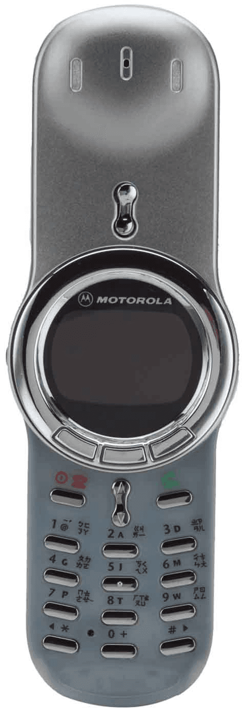
Click to zoom
Application Details
- Equipment Class
- PCE - PCS Licensed Transmitter held to ear
- Date of Grant
- Feb 24, 2002
- Application Purpose
- Original Equipment
- Date of Application
- Feb 24, 2002
- Equipment Note
- PCS GSM Portable Transceiver
- Frequency Range
- 1850.20000000 - 1909.80000000
- Company
- Motorola Mobility LLC
- Country
- United States
Documents & Files
Document Text
Text extracted from the exhibit documents filed with the FCC. Open a document above to read the original.
Users Manual
APPLICANT: MOTOROLA, INC.FCC ID: IHDT6CC1 EXHIBIT 8 INSTRUCTION MANUAL A preliminary draft copy of the Users Manual follows: 1 Welcome Welcome to the world of Motorola digital wireless communications! We are pleased that you have chosen the Motorola V70 wireless phone. Earpiece Headset Jack Insert headset accessory for hands-free use. Volume Key Adjust earpiece and ringer volume. Display Accessory Connector Port Insert charger and phone accessories. Right Soft Key Perform functions identified by right display prompt. Menu Key Power/End Key Press & hold to power phone on & off. Press & release to end phone calls,exit menu system. Send Key Send and answer calls, view recent dialed calls list. Navigation Keys Scroll through menus and lists, set feature values. Left Soft Key Perform functions identified by left display prompt. Microphone User.Guide.GSM.book Page 1 Wednesday, January 9, 2002 2:30 PM 2 Personal Communications Sector 600 North U.S. Highway 45 Libertyville, Illinois 60048 1-800-331-6456 (United States) 1-888-390-6456 (TTY/TDD United States) 1-800-461-4575 (Canada) www.motorola.com (United States) www.motorola.ca (Canada) MOTOROLA, the Stylized M Logo and all other trademarks indicated as such herein are trademarks of Motorola, Inc. ® Reg. U.S. Pat. & Tm. Off. TrueSync, Sidekick, Starfish and the Stylized Starfish Logo are registered trademarks of Starfish Software, Inc., a wholly owned independent subsidiary of Motorola, Inc. All other product or service names are the property of their respective owners. © 2001 Motorola, Inc. All rights reserved. Printed in the U.S.A. Software Copyright Notice The Motorola products described in this manual may include copyrighted Motorola and third party software stored in semiconductor memories or other media. Laws in the United States and other countries preserve for Motorola and third party software providers certain exclusive rights for copyrighted software, such as the exclusive rights to distribute or reproduce the copyrighted softw are. Accordingly, any copyrighted software contained in the Motorola products may not be modified, reverse-engineered, distributed, or reproduced in any manner to the extent allowed by law. Furthermore, the purchase of the Motorola products shall not be deemed to gr ant either directly or by implication, estoppel, or otherwise, any license under the copyrights, patents, or patent applications of Motorola or any third party softw are provider, except for the normal, non-exclusive, royalty-free license to use that arises by operation of law in the sale of a product. Manual number: Cover number: User.Guide.GSM.book Page 2 Wednesday, January 9, 2002 2:30 PM ✂ 3 Menu Map Main Menu • Recent Calls • Received Calls • Dialed Calls • Notepad • Call Times • Call Cost • Service Dial • Fixed Dial • Phonebook • Datebook • Quick Dial • Messages • Voicemail • Text Msgs • Browser Alerts • Info Services • Quick Notes • Outbox • Drafts • Shortcuts • Voice Dial • SIM Applications • Browser • Calculator • Games • Settings (see next page) Note: This is the standard phone menu layout. You or your service provider may have changed the menu layout or changed some feature names. Not all features may be available for all users. Shortcuts Change display zoom: Press M, then press and hold M Display my phone number: Press M # Go to dialed calls list: Press N Exit menu system: Press O User.Guide.GSM.book Page 3 Wednesday, January 9, 2002 2:30 PM ✂ 4 Settings Menu • Ring/Vibrate • Alert • Alert Detail • My Tones • Call Forward • Voice Calls • Fax Calls • Data Calls • Cancel All • Forward Status • Phone Status • My Tel. Numbers • Credit Info/Available • Active Line • Battery Meter • Other Information • Browser Setup • In-Call Setup • In-Call Timer • Call Cost Setup • My Caller ID • Talk and Fax • Answer Options • Call Waiting • Security • Phone Lock • Lock Application • Fixed Dial • Call Barring • SIM Pin • New Passwords • Other Settings • Personalize • Main Menu • Keys • Greeting • Quick Dial • Initial Setup • Time and Date • 1-Touch Dial • Backlight • Zoom • Scroll • Animation • Language • Battery Save • Contrast • DTMF • Master Reset • Master Clear • Network • Car Settings • Headset User.Guide.GSM.book Page 4 Wednesday, January 9, 2002 2:30 PM 5 Contents Menu Map . . . . . . . . . . . . . . . . . . . . . . . . . . . . . . . . . . . . . . 3 About This Guide . . . . . . . . . . . . . . . . . . . . . . . . . . . . . . . 10 Safety and General Information . . . . . . . . . . . . . . . . . . . 12 Getting Started . . . . . . . . . . . . . . . . . . . . . . . . . . . . . . . . 19 What’s in the Box? . . . . . . . . . . . . . . . . . . . . . . . . . . . . . 19 Installing the SIM Card and Battery . . . . . . . . . . . . . . . . . 19 Charging the Battery . . . . . . . . . . . . . . . . . . . . . . . . . . . . 22 Turning Your Phone On . . . . . . . . . . . . . . . . . . . . . . . . . . 23 Sending a Call . . . . . . . . . . . . . . . . . . . . . . . . . . . . . . . . . 25 Ending a Call . . . . . . . . . . . . . . . . . . . . . . . . . . . . . . . . . . 25 Receiving a Call . . . . . . . . . . . . . . . . . . . . . . . . . . . . . . . . 26 Displaying Your Phone Number . . . . . . . . . . . . . . . . . . . . 26 About Your Phone . . . . . . . . . . . . . . . . . . . . . . . . . . . . . . 27 Display . . . . . . . . . . . . . . . . . . . . . . . . . . . . . . . . . . . . . . 27 Changing the Zoom Setting . . . . . . . . . . . . . . . . . . . . . . . 30 Adjusting Volume . . . . . . . . . . . . . . . . . . . . . . . . . . . . . . 31 Battery Use . . . . . . . . . . . . . . . . . . . . . . . . . . . . . . . . . . . 33 Sending and Receiving Calls . . . . . . . . . . . . . . . . . . . . . . 35 Redialing a Number . . . . . . . . . . . . . . . . . . . . . . . . . . . . . 35 Using Automatic Redial . . . . . . . . . . . . . . . . . . . . . . . . . . 35 Caller ID . . . . . . . . . . . . . . . . . . . . . . . . . . . . . . . . . . . . . 36 Line Security . . . . . . . . . .…
Text truncated - open the document above for the full version.
Attestation Statements
APPLICANT MOTOROLA INC.FCC ID: IHDT6CC1 Exhibit 2A ATTESTATION STATEMENTS The transceiver type IHDT6CC1 has been tested in accordance with the requirements contained in the appropriate Commission regulations. To the best of my knowledge, these tests were performed using measurement procedures consistent with industry or Commission standards and demonstrate that this equipment complies with the appropriate standards. Each unit manufactured, imported, or marketed, will conform to the sample tested within the variations that can be expected due to quantity production and testing on a statistical basis. I further certify that the necessary measurements were made at Motorola, located at 600 North U.S. Highway 45, Libertyville, Illinois; or at Motorola, located at 1500 Gateway Boulevard, Boynton Beach, Florida; or at Motorola, located at 2001 N. Division Street, Harvard, Illinois. NAME: John Robin TITLE: Electrical Engineering Section Manager, PCS Development Signed: Date :2/8/2002 APPLICANT MOTOROLA INC.FCC ID: IHDT6CC1 Exhibit 2B The technical data supplied with this application was taken under my supervision and is hereby duly certified. I also certify that this transmit equipment (FCC ID: IHDT6CC1) complies with all applicable parts of the FCC Rules. The following is a statement of my qualifications: NAME: John Robin TITLE: Electrical Engineering Section Manager, PCS Development Signed: Date :2/8/2002 I hereby certify that the above application was prepared under my direction and that to the best of my knowledge and belief, the facts set forth in this application and accompanying technical data are true and correct. NAME: John Robin TITLE: Electrical Engineering Section Manager, PCS Development Signed: Date :2/8/2002
Cover Letter(s)
APPLICANT: MOTOROLAFCC ID: IHDT6CC1 Exhibit 13 February 5, 2002 CONFIDENTIALITY REQUEST CONTAINED WITHIN Federal Communications Commission Authorization and Evaluation Division 7435 Oakland Mills Road Columbia, Maryland 21046 Re: Application for Cellular/PCS Transceiver Certification Gentlemen: Application: Motorola, Inc., Personal Communications Sector, 600 N. U.S. Highway 45, Libertyville, Illinois 60048-1286 herein submits: Application for Equipment Authorization (FCC Form 731-October 1992 with integrated Fee Processing Form, Fee Codes EFT and EBC), application fee in the amount of $640, and Exhibits; for Certification of a PCS Transceiver, FCC ID: IHDT6CC1. Motorola is also the manufacturer of this equipment. Confidentiality: Pursuant to Section 0.459 of the Commission's rules (CFR 47), Motorola requests confidentiality for portions of the material contained in this application and that the identified material be withheld from public inspection following the grant of this authorization. This material contains Motorola's trade secrets and confidential information that Motorola does not customarily release to the public and which is otherwise not generally available to the public. Confidentiality is requested for the following exhibits: • Exhibit 4 Block Diagrams • Exhibit 5 Schematics • Exhibit 12 Operational Description Description: This equipment is a GSM portable transceiver, which operates in the 1900 MHz PCS band Contact Information: Please contact me by telephone at (847) 523-6167, or by e-mail ([email protected]), if there are questions or additional information needed concerning this filing. Regards, Andrew J. Bachler FCC Liaison Cellular Subscriber Sector 600 N. U.S. Highway 45 Libertyville, IL 60048-5343
External Photos
APPLICANT: MOTOROLA, INC. FCC ID: IHDT6CC1 EXHIBIT 3 Front View Rear View, with Battery Removed to Show Equipment ID Label
ID Label/Location Info
APPLICANT: MOTOROLA INC.FCC ID: IHDT6CC1 EXHIBIT 1 FCC IDENTIFICATION (NAMEPLATE) INFORMATION The FCC label shown is representative of the label that will appear on the radio when in production. It will be placed on the outside of the equipment as shown in Exhibit 3. Other information may also be included on this label. FCC ID: IHDT6CC1
Internal Photos
APPLICANT: MOTOROLA, INC. FCC ID: IHDT6CC1 EXHIBIT 9 Front View (Shields Removed) Rear View (Shields Removed)
Parts List/Tune Up Info
APPLICANT: MOTOROLA, INC.FCC ID: IHDT6CC1 EXHIBIT 10 TRANSCEIVER ADJUSTMENTS/TUNE-UP PROCEDURE There are no user accessible adjustments or tuning in this portable cellular transceiver. All necessary adjustments and tuning are performed during manufacture of the product. Any adjustments or tuning after service or repair are done as part of that process as special equipment is required to perform such adjustments.
RF Exposure Info
APPLICANT: MOTOROLA, INC. FCC ID: IHDT6CC1 E E x x h h i i b b i i t t 1 1 1 1 P P a a g g e e 1 1 Exhibit 11: SAR Test Report IHDT6CC1 Date of test: Date of Report: 02/07/02 – 02/11/02 02/11/02 Laboratory: Motorola Personal Communications Sector Product Safety & Compliance Laboratory 2001 N. Division Room: AS228 Harvard, Illinois 60033 Test Responsible: Firass Badaruzzaman SAR RF Engineer Accreditation: This laboratory is accredited to ISO/IEC 17025-1999 to perform the following electromagnetic exposure tests: System Validation & Interlaboratory Comparison Simulated Tissue Specifications and Procedure EME Cellular Phone Testing Procedure On the following types of products: Wireless Communications Devices (Examples): Two Way Radios; Portable Phones (including Cellular, Licensed Non-Broadcast and PCS); Low Frequency Readers; and Pagers A2LA certificate #1651-01 Statement of Compliance: Motorola declares under its sole responsibility that portable cellular telephone FCC ID IHDT6CC1 to which this declaration relates, is in conformity with the appropriate RF exposure standards, recommendations and guidelines (FCC 47 CFR §2.1093). It also declares that the product was tested in accordance with the appropriate measurement standards, guidelines and recommended practices. Any deviations from these standards, guidelines and recommended practices are noted below: (none) ©Motorola, Inc. 2001 This test report shall not be reproduced in full, without written approval of the laboratory. The results and statements contained herein relate only to the items tested. The names of individuals involved may be mentioned only in connection with the statements or results from this report. Motorola encourages all feedback, both positive and negative, on this test report. APPLICANT: MOTOROLA, INC. FCC ID: IHDT6CC1 E E x x h h i i b b i i t t 1 1 1 1 P P a a g g e e 2 2 Table of Contents 1) Introduction 3 2) Description of the Device Under Test 3 Antenna description 3 Device description 3 3) Test Equipment 3 3.1 Dosimetric system 3 3.2 Additional equipment used 4 4) Electrical parameters of the tissue simulating liquid 4 5) System Accuracy Verification 4 6) Test Results 5 6.1 Head Adjacent Test Results 5 6.2 Body-Worn Test Results 7 Reference Notes Appendix 1: SAR distribution comparison for the system accuracy verification 8 Appendix 2: SAR distribution plots for Phantom Head Adjacent Use 9 Appendix 3: SAR distribution plots for Body Worn Configuration 11 Appendix 4. Probe Calibration Certificate 13 Appendix 5: Photographs of the device under test 14 APPLICANT: MOTOROLA, INC. FCC ID: IHDT6CC1 E E x x h h i i b b i i t t 1 1 1 1 P P a a g g e e 3 3 1. Introduction The Motorola Personal Communications Sector Product Safety Laboratory has performed measurements of the maximum potential exposure to the user of portable cellular phone FCC ID IHDT6CC1. The Specific Absorption Rate (SAR) of this product was measured. The portable cellular phone was tested in accordance with the latest available test guidelines. 2. Description of the Device Under Test Antenna description Type Stubby Location Right Side Length 37mm Dimensions Width 6mm Configuration Helix Device description FCC ID Number IHDT6CC1 Serial number EGB0021 Mode(s) of Operation GSM 1900 Modulation Mode(s) GSM Maximum Output Power Setting 30.50 dBm Duty Cycle 1:8 Transmitting Frequency Rang(s) 1850.2 –1909.8 MHz 3. Test Equipment Used 3.1 Dosimetric System The Motorola Personal Communications Sector Product Safety Laboratory utilizes a Dosimetric Assessment System (Dasy3™ v3.1d) SAR measurement system manufactured by Schmid & Partner Engineering AG (SPEAG™), of Zurich Switzerland. The overall RSS uncertainty of the measurement system is ±12.0% (K=1). Description Serial Number Cal Due Date DASY3 DAE V1 SN367 30-Jul-02 E-Field Probe ETDV6 SN1397 23-Nov-02 Dipole Validation Kit, DV1900V2 SN280 4-Jan-03 Flat Phantom used for 1900MHz TP-1105 Description Serial Number Cal Due Date DASY3 DAE V1 SN398 26-Sep-02 E-Field Probe ETDV6 SN1398 31-Aug-02 Dipole Validation Kit, DV1900V2 SN280 4-Jan-03 Flat Phantom used for 1900MHz APPLICANT: MOTOROLA, INC. FCC ID: IHDT6CC1 E E x x h h i i b b i i t t 1 1 1 1 P P a a g g e e 4 4 3.2 Additional Equipment Description Serial Number Cal Due Date Signal Generator HP8648C 3847A04843 11/15/2002 Power Meter E4419B GB39511087 11/16/2002 Power Sensor 8481A US37296473 10/1/2002 Network Analyzer HP8753ES US39172529 7/5/2002 4. Electrical parameters of the tissue simulating liquid Prior to conducting SAR measurements, the relative permittivity, ε r , and the conductivity, σ, of the tissue simulating liquids were measured with HP85070 Dielectric Probe Kit These values are shown in the table below. Recommended limits for maximum permittivity and minimum conductivity are also shown. These come from the Federal Communication Commission, OET Bulletin 65 Supplement C 01-01. The recommended dielectric parameters of the tissue simulant for the exact center frequency of the transmitting band of this portable radio were calculated using linear interpolation from the data points given in Supplement C 01-01. It is seen that the measured parameters are satisfactory for compliance testing. The issue stimulant depth was verified to be 15.0cm ±0.5cm at the center of the ear. The stimulant temperature was measured at the beginning and end of each day. The values measured at the start of each day are shown in the table below. The ambient temperature was also measured throughout the day. The ambient temperature measurements and the tissue stimulant temperature measurements always found the temperature ±2.0 °C from the temperature measured in the morning. f Dielectric Parameters (MHz) Tissue type Limits / Measured ε r σ (S/m) Temp (°C) Measured, 02/07/02 38.10 1.44 20.00 Head Recommended Limits 40.00 1.40 N/A 1880 Measured, 02/10/02 50.90 1.60 22.00 Body Recommended Limits 53.30 1.52 N/A 5. System Accuracy Verification A system accuracy verification of the DASY…
Text truncated - open the document above for the full version.
RF Exposure Info
1 February 22, 2002 Supplement to SAR Test Report for Motorola portable cellular phone (FCC ID: IHDT6CC1) Prepared by: Firass Badaruzzaman, SAR RF Engineer Motorola Personal Communications Sector Product Safety Laboratory Harvard, Illinois 2 Summary of FCC request for additional information There was a request for additional information regarding Motorola’s SAR Test Report for Motorola portable cellular phone (FCC ID IHDT6CC1). The requested information is addressed below in the same numbering sequence received. 1.) Please verify that there is only one battery type used with this phone. There is only one type of battery used with this product. This is the battery that was used in the measurements reported. 2.) Please confirm your liquid depth with photo or provide a z-axis scan plot of the highest SAR. Please look at below figures: Figure 1. Location of Tissue Simulate Depth Measurement Location in Phantom Head 3 Figure 2. Location of Tissue Simulate Depth Measurement Location in Phantom Head 3.) Please specify composition of ingredients for the tissue liquids used. The ingredients for the liquid tissue are the same as the ones recommended by FCC OET Bulletin 65 Supplement C 01-01 (Appendix C : Tissue Dielectric Parameters – Page 38). The amounts of each were: Frequen cy (MHz) Ingredients of the Tissue Liquid Head Simulate (% by Weight) Body Simulate (% by Weight) DGBE47.0030.80 Water52.8068.91 1880 MHz Salt0.200.29 4.) Justification of the 15 degree/Tilt Position tested only at the mid channel, which deviates from the FCC/OET Supplement C recommendation. Please explain. The 15-degree/Tilt-position measurement was performed in accordance with FCC OET Bulletin 65 Supplement C 01-01 standard, which states: 4 “The device should be tested on the left and right side of the head phantom in the “Cheek/Touch” and “Ear/Tilt” positions. When applicable, each configuration should be tested with the antenna in its fully extended and fully retracted positions. These test configurations should be tested at the high, middle and low frequency channels of each operating mode; for example, AMPS, CDMA, and TDMA. If the SAR measured at the middle channel for each test configuration (left, right, Cheek/Touch, Tile/Ear, extended and retracted) is at least 2.0 dB lower than the SAR limit, testing at the high and low channels is optional for such test configuration(s).” (Appendix D: SAR Measurement Procedures – Page 42). The measured SAR was below this threshold and thus the additional tests were not required. 5.) The RF safety statement distance for body worn use in the manual on page 14 does not agree with Page 19 of the SAR Test report. Please clarify. Good point. A clarification follows: • The 2.5-cm distance, indicated on page 14 of the manual, addresses operating configurations which do not use a Motorola supplied body worn device. At this distance, the SAR value is lower than the body worn value reported in the SAR report. • The distances, on page 19 of the SAR report, specify the actual parameters when the supplied body worn device is used. Even though these distances are greater than the 2.5-cm specified in the manual, the measured SAR value is higher and is therefore reported. Note: The body worn device on Page 19 of the SAR Test report contains metal components (spring and clip). 6.) Please describe methods and reasons for extrapolated SAR data as shown in the tabulated SAR summary. The exact method of extrapolation is New SAR = Old SAR * 10^(drift/10). The SAR reported at the end of the measurement process by DASY can be scaled up by the measured drift to determine the SAR at the beginning of the measurement process (this is the worst case SAR when there are negative drifts).
RF Exposure Info
April 19, 2002 Supplement to SAR Test Report for Motorola portable cellular phone (FCC ID IHDT6CC1). Prepared by: Steven Hauswirth, Senior Staff Engineer Motorola Personal Communications Sector Product Safety Laboratory Harvard, Illinois Summary of request for additional information There was a request for additional information regarding Motorola’s SAR Test Report for Motorola portable cellular phone (FCC ID IHDT6CC1). The requested information is addressed below in the same numbering sequence received. 3) Please justify use of ConvF=5.47 for head. Exhibit "Addl. Conv. Fact." for probe sn. 1397 shows ConvF=5.2. Lower ConvF means higher SAR, means max SAR goes from 1.54 to 1.62. The SAR plots show that Probe S/N: 1397 used a Conversion Factor of 5.47 for 1800-1900MHz head. This value is shown on the “Calibration Certificate” on the 3 rd page, located under the heading of “Head 1700-1910MHz”. Please do not confuse the 1950MHz head and body tissue conversion factors shown in the “Additional Conversion Factors” for probe 1397 with the values used. The conversion factors for 1950MHz are intended to be used for products that have UMTS modulation (3G).
Test Report
APPLICANT: MOTOROLA INCFCC ID: IHDT6CC1 EXHIBIT 6 PERSONAL COMMUNICATIONS SECTOR PRODUCT SAFETY AND COMPLIANCE EMC LABORATORY EMC TEST REPORT Test Report Number – 6003-2 Report Date – February 11, 2002 The test results contained herein relate only to the model(s) identified. It is the manufacturer’s responsibility to assure that additional production units of this model are manufactured with identical electrical and mechanical characteristics. As the responsible EMC Engineer, I hereby declare that the equipment tested as specified in this report conforms to the requirements indicated. SignatureName: _Kirby Munroe__ Title: Compliance Engineer Date : _ 2/11/2002____ This report must not be reproduced, except in full, without written approval from this laboratory. THIS REPORT MUST NOT BE USED TO CLAIM PRODUCT ENDORSEMENT BY A2LA OR ANY AGENCY OF THE U.S. GOVERNMENT. A2LA Certificate Number: 1846-01 APPLICANT: MOTOROLA INCFCC ID: IHDT6CC1 Test Report Number: 6003-2EXHIBIT 6 2 Test Report Details Tests Performed By:Motorola Personal Communications Sector Product Safety and Compliance Group 1500 Gateway Boulevard Boynton Beach, FL 33426 PH (561) 739-2179 Fax (561) 739-2131 Tests Requested By:Motorola Inc. Personal Communications Sector 600 North US Hwy 45 Libertyville, IL 60048 Product Type:Cellular Phone Signaling Capability:GSM 1900 Model Number:SUG2378A Serial Numbers:EGB0035, EE30068, EGB0099 Received Date:February 7, 2002 Testing Start Date:February 7, 2002 Testing Complete Date:February 10, 2002 Measurement of Uncertainty:+/- 3.8 dB Applicable Standards All tests and measurements indicated in this document were performed in accordance with the Code of Federal Regulations Title 47 Part 2, Sub-part J as well as the following parts: Part 22 Subpart H - Public Mobile Services X Part 24 - Personal Communications Services Part 90 - Private Land Mobile Radio Service Applicable Standards: ANSI 63.4 2000 APPLICANT: MOTOROLA INCFCC ID: IHDT6CC1 Test Report Number: 6003-2EXHIBIT 6 3 Summary of Testing Test Test Name Comply Does Not # Comply 1RF Power OutputNA 2EIRPNA 3Occupied BandwidthNA 4Spurious Emissions at Antenna TerminalX 5Field Strength of Spurious EmissionsX 6Frequency StabilityX 7Field Strength of Radiated EmissionsX from Unintentional Radiators TestTest Name Margin with respect # to the Limit_________ 1RF Power Output NA 2EIRPNA 3Occupied Bandwidth NA 4Spurious Emissions at Antenna Terminal 17.6 dB 5Field Strength of Spurious Emissions 12.8 dB 6Frequency Stability 151.5 Hz 7Field Strength of Radiated Emissions 2.8 dB from Unintentional Radiators The margin with respect to the limit is the minimum margin for all modes and bands. General and Special Conditions The EUT was tested using a fully charged battery when applicable. Where a battery could not be used due to the need for a controlled variation of input voltage, an external power supply was utilized. All testing was done in an indoor controlled environment with an average temperature of 22º C and relative humidity of 50%. APPLICANT: MOTOROLA INCFCC ID: IHDT6CC1 Test Report Number: 6003-2EXHIBIT 6 4 Equipment and Cable Configurations The EUT was tested in a stand-alone configuration that is representative of typical use. Measuring Equipment and Calibration Information ManufacturerItemItem Version/Serial CALIBRATION NameNameModel #NumberDUE DATE Description Rohde & SchwarzEMI Test ReceiverESI26 100001 3/13/2002 Rohde & SchwarzEMI Test ReceiverESI26 838386/010 2/28/2002 Hewlett PackardRF Amplifier8347A3307A012257/30/2002 Hewlett PackardPre-Amplifier8449B3008A005357/2/2002 ETSDRG Horn Antenna311562229/23/2002 A.H. Systems Inc.DRG Horn AntennaSAS-200/5712658/21/2002 A.H. Systems Inc.DRG Horn AntennaSAS-200/57136511/14/2002 ETSLog-Periodic Antenna3148118812/6/2002 ETSBiconical Antenna3110B337010/16/2002 Compliance DesignBiconical AntennaB1003857/31/2002 Compliance DesignBiconical AntennaB2003129/15/2002 Compliance DesignBiconical AntennaB3003217/30/2002 AttenuatorWeinschel AS-6667510/10/2002 AttenuatorWeinschel AS-6667711/10/2002 EMCOLISN3810/221791/20/2002 Rohde & SchwarzMobile Test SetCMD 80DE2900810/18/2002 Hewlett Packard Signal Generator 83623B 3844A01195 1/16/2003 ThermotronEnvironmental ChamberS-43158012/20/2002 All equipment is on a one-year calibration cycle. APPLICANT: MOTOROLA INCFCC ID: IHDT6CC1 Test Report Number: 6003-2EXHIBIT 6 5 Measurement Procedures and Data RF POWER OUTPUT Measurement Procedure The RF output port of the equipment under test is directly coupled to the input of a HPE4406A Vector Signal Analyzer through a 10dB passive attenuator, adaptor (if needed), and specialized RF connector. The peak power output is measured for all channels. CFR Part 2.1046 Measurement Results * Data not supplied by EMC Lab GSM 1900 Frequency (MHz) Power (dBm) 1850.230.84 1880.030.73 1909.830.78 APPLICANT: MOTOROLA INCFCC ID: IHDT6CC1 Test Report Number: 6003-2EXHIBIT 6 6 RADIATED (EIRP) Measurement Procedure The phone was tested in Harvard Chamber 1, which is a 16' cubical anechoic chamber with a 2-axis positioner system that permits taking complete spherical scans of the AUT's radiation patterns. For all tests, the phone was supported in a free-space type environment, vertically oriented in the chamber. Tests were done for GSM 1900 three frequencies (1850.2, 1880.0 and 1909.8 MHz) with antenna stubby. GSM measurements were made with the phone placed in a call using the HP8922M mobile station test set. The phone was weakly coupled to the test set and configured to transmit in full data rate mode, with a nominal output power setting of 29.5 dBm for 1900. Radiated power was measured at every 15 degree step from theta=0 to 165 degrees and phi=0 to 360 degrees. The radiated power was measured using a Gigatronics 8542C power meter in "Burst Avg" mode. From these measurements, the software calculates the angle at which maximum radiated power occurs for each case, and the radiated power at this angle was extracted from the data. The max rad…
Text truncated - open the document above for the full version.
Contact Information
Applicant
Jeff Narducci(Director Product Compliance)
Test Firm
Motorola Inc.Jonathan Munroe
Technical Specifications
| # | Rule Parts | Frequency Range | Power Output | Emission | Tolerance |
|---|---|---|---|---|---|
| 1 | 24E | 1.85 GHz - 1.91 GHz | 1.16 W | 250KGXW | 0.1000000000 ppm |
Other Applications from Motorola Mobility LLC
IHDT6AC8
Sep 15, 2026Qi2 wireless charger
Equipment Class
DCD - Part 15 Low Power Transmitter Below 1705 kHzIHDT6AC6
Sep 14, 2026Wireless Earphones
Equipment Class
JAB - Part 15 Class B Digital DeviceIHDT6AC7
Sep 11, 2026Smart Watch
Equipment Class
JAB - Part 15 Class B Digital DeviceIHDT56AX5
Aug 28, 2026Mobile Cellular Phone
Equipment Class
JBP - Part 15 Class B Computing Device PeripheralIHDT56AW9
May 12, 2026Smart Watch
Equipment Class
NII - Unlicensed National Information Infrastructure TX