IHDT6FL1PCS GSM Transceiver PCMCIA Card
Motorola Mobility LLC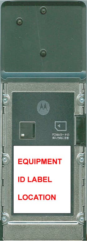
Click to zoom
Application Details
- Equipment Class
- PCB - PCS Licensed Transmitter
- Date of Grant
- Aug 30, 2006
- Application Purpose
- Original Equipment
- Date of Application
- Aug 30, 2006
- Equipment Note
- PCS GSM Transceiver PCMCIA Card
- Frequency Range
- 1850.20000000 - 1909.80000000
- Company
- Motorola Mobility LLC
- Country
- United States
Documents & Files
Document Text
Text extracted from the exhibit documents filed with the FCC. Open a document above to read the original.
Users Manual
APPLICANT: MOTOROLA, INC. FCC ID: IHDT6FL1 INSTRUCTION MANUAL • A preliminary draft copy of the User’s Manual follows this cover page. • The User’s Manual will have the following text added to it: "NOTE: This equipment has been tested and found to comply with the limits for a Class B digital device, pursuant to Part 15 of the FCC Rules. These limits are designed to provide reasonable protection against harmful interference in a residential installation. This equipment generates, uses and can radiate radio frequency energy and, if not installed and used in accordance with the instructions, may cause harmful interference to radio communications. However, there is no guarantee that interference will not occur in a particular installation. If this equipment does cause harmful interference to radio or television reception, which can be determined by turning the equipment off and on, the user is encouraged to try to correct the interference by one or more of the following measures: . Reorient or relocate the receiving antenna. . Increase the separation between the equipment and receiver. . Connect the equipment into an outlet on a circuit different from that to which the receiver is connected. . Consult the dealer or an experienced radio/TV technician for help." NOTE: Text from FCC Part 15.19(a) will be included in the production version of the user's manual. EXHIBIT 8 DoCoMo W-CDMA and GSM/GPRS Systems Thank You for Purchasing the “FOMA M2501 HIGH- SPEED”. Before or while using the FOMA M2501 HIGH-SPEED, be sure to thoroughly read this manual to ensure its correct use. For further information, contact the “DoCoMo Information Center” on the back page of this manual. Treated with care, your FOMA M2501 HIGH-SPEED will be your able partner. Before Using the FOMA M2501 HIGH-SPEED Because the FOMA terminal uses radio waves, it may not function in locations where it is difficult for radio waves to penetrate, such as tunnels, underground passages and some buildings; in areas where radio wave signals are weak; or out of the service area. Even when you are on a higher floor of a tall building or condominium and nothing blocks your view outside, the FOMA M2501 HIGH-SPEED may not be able to receive or transmit signals. Also, communication may be interrupted even when the signal reception level on the FOMA M2501 HIGH-SPEED is strong in a fixed location. Use the FOMA M2501 HIGH-SPEED in ways that do not disturb others in public places, crowded locations, or quiet. Because the FOMA M2501 HIGH-SPEED uses radio waves to communicate, there is a possibility that a third party intercepts communications. However, the W-CDMA and GSM/ GPRS systems automatically support encoding for all calls, so even if a third party intercepts a call, the third party hears only noise. The FOMA terminal encodes voice communication on to digital signals and communicates via wireless. When you use the FOMA M2501 HIGH-SPEED at a location with weak radio wave signals, the transmitted digital signals may not be correctly decoded and the decoded voice may sound different from the original one. It is recommended that you make separate notes of the information stored in your PC and keep such notes in a safe place. DoCoMo cannot be held responsible in any way for loss of data stored in your PC. The FOMA M2501 HIGH-SPEED supports FOMA Plus-Area. The FOMA terminal can be used only via the FOMA network provided by DoCoMo and DoCoMo’s roaming area. This FOMA terminal does not support i-mode functions (i-mode mail, connection to official i-mode sites or i-appli, etc.). This FOMA terminal cannot receive SMS (Short Message Service). Therefore, it is recommended that you set to reject receiving all SMS messages. For details on setting to reject all SMS, refer to “ (Network Service Operation Guide)”. For Those Who Use the FOMA Terminal for the First Time If this is the first time for you to use the FOMA terminal, it is recommended that you read this manual in the following order to learn basic operations. 1. Learning names of parts and functions of the FOMA terminal ........................................... P16 2. Connecting the FOMA terminal and a PC ........................................................................... P21 3. Having the FOMA terminal recognized by your PC............................................................. P24 4. Setting up the FOMA terminal for communication...................................................... P24, P29 The latest version of this manual can be downloaded from the DoCoMo Web site. Download the “Instruction Manual (PDF File)” (http://www.nttdocomo.co.jp/english/support/manual/index.html) * The URL and the information contained in the manual are subject to change without prior notice. 1 How to Read/Refer to This Manual In this manual, illustrations and symbols are used in the explanations so that you can easily understand how to use the FOMA terminal correctly. • This manual describes operations mainly using a mouse to click on an item. How to Refer to This Manual By the following search methods, you can find pages where functions and services are described: Overseas Use See “Overseas Use” when using the terminal overseas. P77 • This manual refers to the “FOMA M2501 HIGH-SPEED” as the “FOMA terminal”. • Reprinting all or parts of this manual without approval of NTT DoCoMo is prohibited. • Information contained in this manual is subject to change without prior notice. From the Index Search from the index when you know the names of functions or services. From the Tabs on the Front Cover Search from the tabs printed on the front cover. From the ContentsP4 Search from the contents that categorize functions. From FeaturesP5 Search from the features when you want to use specific functions. See the next page for details. 2 From the IndexP95 Search for a function name or a service name as shown below. From the Tabs on the Front CoverFront cover Search for the function you want to set in the order of “Front c…
Text truncated - open the document above for the full version.
Users Manual
48 Setting Up Values displayed after n=4 is entered using AT commands : Controllable : Uncontrollable ATZReset the settings on the FOMA terminal with the non-volatile memory content. If performed during a communication, the line is disconnected. (On-line command mode) ATZ NO CARRIER (Off-line) ATZ OK Controllable function Values displayed after command entry 0123456789101112131415 64K data communication Video calls PPP packet communication Voice calls AT CommandOverviewParameters/DescriptionCommand Examples AT Command List 49 Setting Up Supplementary Explanation of AT Commands Command name : +CGDCONT • Overview Set APN when sending packet connection. •Form +CGDCONT=[<cid>[,“<PDP type>” [ ,“<APN>”] ] ] • Parameter descriptions Set APN when sending Packet communication. See examples in command operation lists <cid>*: X to X <PDP type>* : PPP or IP <APN>*: Optional *: <cid> is the number used to control the destination (APN) for the Packet communication to be registered in FOMA terminal. X to X can be registered. <PDP type> is a protocol for packet communication. <APN> is optional connection name that indicates each destination. • Operation without parameter AT+CGDCONT=<cid> : Set specified <cid> as default AT+CGDCONT=? : Display list of values that can be configured AT+CGDCONT=? : Display list of values that can be configured • Command examples Registered APN named abc (When PDP type is “PPP” and cid=3) AT+CGDCONT=3,“PPP”,“abc” OK * This command, which is a setting command, is not stored in the nonvolatile memory written by [&W] and is not reset by [&F] and [Z], either. Command name : +CGEQMIN=[Parameter] • Overview Register criteria value to determine if QoS sent from network when Packet communication established is permitted. •Form +CGEQMIN=[<cid>[,,<Maximum bit rate UL>[, <Maximum bit rate DL>] ] ] • Parameter description <cid>* : X to X <Maximum bit rate UL>* : None (default) or 64 <Maximum bit rate DL>* : Non (default) or 384 *: <cid> is the number used to control the destination (APN) for the Packet communication to be registered in FOMA terminal. X to X can be registered. In <Maximum bit rate UL> and <Maximum bit rate DL>, the minimum connection speed [Kbps] is set for both upload and download traffic between FOMA terminal download traffic between FOMA terminal and the base station. If the parameter is set to None (default), all speeds are permissible. If 64 and 384 are set, any communication at a speed except the above limit is not permitted, and the Packet communication will not be connected. • Operation without parameter AT+CGEQMIN= : Set all <cid> as default value AT+CGEQMIN=<cid> : Set specified <cid> as default value • Command examples (1) Command used to permit all speed both upload and download both upload and download (when<cid>=2) AT+CGEQMIN=2 OK (2) Command used to permit only 64Kbps upload and 384Kbps download (when<cid>=2) AT+CGEQMIN=2,,64,384 OK (3) Command used to permit 64Kbps upload and all speed download (when<cid>=3) AT+CGEQMIN=3,,64 OK (4) Command used to permit all speed upload and only 384Kbps download (when<cid>=3) AT+CGEQMIN=3,,,384 OK * This command, which is a setting command, is not stored in the nonvolatile memory written by [&W], and is not reset by [&F] and [Z], either. Command name : +CGEQREQ=[Parameter] • Overview Sets up QoS request to the network when Packet communication is established. •Form +CGEQREQ=[<cid>[,,<Maximum bit rate UL> [ ,<Maximum bit rate DL>] ] ] • Parameter Description <cid>* : X to X <Maximum bit rate UL>* : None (default) or 64 <Maximum bit rate DL>* : None (default) or 384 *: <cid> is the number used to control the destination (APN) for the Packet communication to be registered in FOMA terminal. 1 to 3 can be registered to FOMA terminal. In <Maximum bit rate UL> and <Maximum bit rate DL>, the minimum connection speed [in Kbps] is set for both upload and download traffic between FOMA terminal and the base station. If the parameter is set to None (default), all speeds are permissible. If 64 and 384 are set, any connection at a speed except the above limit is not permitted, and the Packet communication will not be connected. • Operation without parameter AT+CGEQREQ=<cid> : Set all <cid> as default. AT+CGEQREQ=<cid> : Set specified <cid> as default. • Command examples Command used to require 64Kbps upload and 384Kbps download (when<cid>=3) AT+CGEQREQ=3,,64,384 OK AT Command List Continued on the next page 50 Setting Up * This command, which is a setting command, is not stored in the nonvolatile memory written by [&W], and is not reset by [&F] and [Z], either. List of Reasons of Disconnection (Checking the specification) Result Codes List of Result Code Extended Result Codes When &E0 Show the connection speed between the FOMA terminal and the base. When &E1 Communication Protocol Result Codes Examples of Displayed Result Codes When ATX0 is set Regardless of the AT Commands (P46) settings, only CONNECT is displayed after connection is established. Example of text display: ATD991# CONNECT Example of numeric display : ATD991# 1 When ATX1 is set • When ATX1, ATV0 is set (default) Display in the format of CONNECT <Speed between FOMA and PC> after the connection is established. Example of text display :ATD991# CONNECT 460800 Example of numeric display :ATD991# 121 • When ATX1, ATV1 is set Display in the following format after the connection is established. CONNECT <Speed between FOMA and PC> PACKET <Destination APN>/<Maximum uplink speed (between FOMA terminalBase)> / <Maximum downlink speed (between FOMA terminalBase)> Example of text display :ATD991# CONNECT 46080 PACKET mopera.ne.jp/64/384 (which means connection is established with mopera.ne. jp/64/384mopera.ne.jp/64/384.) Example of numeric display :ATD991# 1215 * If ATX1 and ATV1 are set concurrently, a dial-up connection may not be executed correctly. It is recommended to use only ATV0. No.Text displayDescription 0OKOperation performed properly. 1CONNECTConnected to the other party. …
Text truncated - open the document above for the full version.
Attestation Statements
APPLICANT: MOTOROLA INC. FCC ID: IHDT6FL1 STAEMENT OF CERTIFICATION Transceiver type FCC ID: IHDT6FL1 has been tested in accordance with the requirements contained in the appropriate Commission regulations. To the best of my knowledge, these tests were performed using measurement procedures consistent with industry or Commission standards and demonstrate that this equipment complies with the appropriate standards. Each manufactured imported or marketed, will conform to the sample tested within the variations that can be expected due to quantify production and testing on a statistical basis. I further certify that the necessary measurements were made at: Motorola Personal Communication Sector Product Safety and Compliance Group 600 North US Hwy 45 Libertyville, IL 60048 NAME: Reuven Konevky TITLE: HW manager DATE: July 21, 2006 Page 1 of 2 Exhibit 2 APPLICANT: MOTOROLA INC. FCC ID: IHDT6FL1 STAEMENT OF CERTIFICATION I hereby certify that the above application was prepared under my direction and that to the best of my knowledge and belief, the facts set forth in this application and accompanying technical date are true and correct. The technical data supplied with this application was taken under my supervision and is herby duly certified. I also certify that this transmit equipment (FCC ID: IHDT6FL1) is in compliance with all applicable parts of the FCC Rules. NAME: Reuven Konevky TITLE: HW Manager DATE: July 21, 2006 Page 2 of 2 Exhibit 2
Cover Letter(s)
APPLICANT: MOTOROLA, INC. FCC ID: IHDT6FL1 July 11, 2006 CONFIDENTIALITY REQUEST CONTAINED WITHIN Federal Communications Commission Authorization and Evaluation Division 7435 Oakland Mills Road Columbia, Maryland 21046 Re: Application for Cellular/PCS Transceiver Certification Gentlemen: Application: Motorola, Inc., Mobile Devices, 600 N. U.S. Highway 45, Libertyville, Illinois 60048 herein submits: Application for Equipment Authorization for Certification of a Cellular Transceiver, FCC ID: IHDT6FL1. Motorola is also the manufacturer of this equipment. Confidentiality: Pursuant to Section 0.459 of the Commission's rules (CFR 47), Motorola requests confidentiality for portions of the material contained in this application and that the identified material be withheld from public inspection following the grant of this authorization. This material contains Motorola's trade secrets and confidential information that Motorola does not customarily release to the public and which is otherwise not generally available to the public. Confidentiality is requested for the following exhibits: • Exhibit 4 Block Diagrams • Exhibit 5 Schematics • Exhibit 10 Parts List • Exhibit 12 Operational Description Description: This equipment is a GSM portable transceiver, which operates in the 1900 MHz PCS band. The unit is intended to be connected to a computer via a PC Slot (Part 15, Class B, Computing Device Peripheral). Note: This device contains 900 MHz and 1800 MHz GSM, functions that are not operational in U.S. territories. This unit also supports power class 3 WCDMA 2100/800 that is not operational in the U.S. Contact Information: Please contact me by telephone at (847) 523-6167, or by e-mail ( [email protected]), if there are questions or additional information needed concerning this filing. Regards, Andrew J. Bachler FCC Liaison Mobile Devices 600 N. U.S. Highway 45 Libertyville, IL 60048 Exhibit 13
Cover Letter(s)
Date: August 30, 2006 Subject: Request for additional information regarding FCC ID: IHDT6FL1 Reference: Correspondence Reference Number: IHD0385 Confirmation Number: 1607110385/86 Date of Original Email: 08/23/06 Prepared by: Andrew Bachler, Principal Staff Engineer Motorola Mobile Device Business Libertyville, Illinois Questions and responses follow: 1. Please specify the detector function used to perform spurious radiated and conducted measurements for Part 24 operation. Response: A peak detector is used for spurious emission measurements, for intentional radiators. The RBW = 1MHz and VBW >= RBW. 2. The SAR report, in the introduction and description of the EUT, refers to it as a phone. Please address. Response: Please refer to the supplemental SAR report and revised SAR report submitted on August 30, 2006. 3. Please specify the make/model/ FCC ID of the 3 laptop pc’s used during SAR tests. Response: Please refer to the supplemental SAR report and revised SAR report submitted on August 30, 2006. 4. The Part 24 test set up photos appear to show a phone, and not the EUT. Please address. Response: Please refer to the following test set up photo: 1 5. Please submit a Part 15B test report. Response: Please refer to exhibit 6B, submitted on August 30, 2006. 6. Please verify that the statement required by Section 15.21 will be included in the user’s manual prior to shipment of the EUT. Response: The final version of the user’s manual will include the required Section 15.21 statement. 7. The RFx statement in the user’s manual consistently refers to the EUT as a phone, and is not applicable to the EUT. It also lists a minimum required separation distance of 1.5 cm, which, again, is not applicable. Please address. Response: The final version of the user’s manual refers to the EUT as a PC card, and the rf exposure language is changed to: The highest SAR value for this product when tested for use in normal operating conditions inside a laptop, with the laptop against the body, is: 0.55 W/kg. 8. The maximum SAR level listed in the user’s manual is 0.49, but the data shows a maximum level of 0.52. Please correct. Response: The final version of the user’s manual states the highest SAR value as 0.55 W/kg. 2
External Photos
APPLICANT: MOTOROLA, INC. FCC ID: IHDT6FL1 Front View Rear View EXHIBIT 3 1
ID Label/Location Info
APPLICANT: MOTOROLA INC. FCC ID: IHDT6FL1 FCC IDENTIFICATION (NAMEPLATE) INFORMATION FCC ID: IHDT6FL1 The FCC label shown is representative of the label that will appear on the radio when in production. It will be placed on the outside of the equipment as shown in Exhibit 3. Other information may also be included on this label. Exhibit 1
Internal Photos
APPLICANT: MOTOROLA, INC. FCC ID: IHDT6FL1 Top side view with shields Bottom side view with shields EXHIBIT 9 1 APPLICANT: MOTOROLA, INC. FCC ID: IHDT6FL1 Top side shields removed Bottom side shields removed EXHIBIT 9 2 APPLICANT: MOTOROLA, INC. FCC ID: IHDT6FL1 Front housing internal view Rear housing internal view EXHIBIT 9 3
RF Exposure Info
0 0 Data Card SAR Test Report Test Report #: 18697-1F Date of Report: 8/30/2006 Date of Test: 7/7/2006-7/13/2006 FCC ID #: IHDT6FL1 Generic Name: MJT6-33411A11 Laboratory: Motorola Mobile Devices Business Product Safety & Compliance Laboratory 600 N. US Highway 45 Libertyville, Illinois 60048 Report Author: Paul Ma RF Engineer Accreditation: This laboratory is accredited to ISO/IEC 17025-1999 to perform the following tests: Tests : Procedures: Electromagnetic Specific Absorption Rate ANSI / IEEE C95.1-1992, 1999 (SAR) IEEE C95.3-1991 IEEE 1528, IEC 62209-1 FCC OET Bulletin 65 (including Supplements A, B, C) Australian Communications Authority Radio Communications (Electromagnetic Radiation – Human Exposure) Standard 2003 CENELEC EN 50361 (2001) Simulated Tissue Preparation WI-0247 RF Power Measurement WI-1847 On the following products or types of products: Wireless Communications Devices (Examples): Two Way Radios; Portable Phones (including Cellular, Licensed Non-Broadcast and PCS); Low Frequency Readers; and Pagers A2LA certificate #1651-01 Statement of Compliance: Motorola declares under its sole responsibility that the data card model to which this declaration relates, is in conformity with the appropriate General Population/Uncontrolled RF exposure standards, recommendations and guidelines (FCC 47 CFR §2.1093) as well as with CENELEC en50360:2001 and ANSI / IEEE C95.1. It also declares that the product was tested in accordance with CENELEC en50361:2001, IEEE 1528, as well as other appropriate measurement standards, guidelines and recommended practices. Any deviations from these standards, guidelines and recommended practices are noted below: (none) ©Motorola, Inc. 2006 This test report shall not be reproduced except in full, without written approval of the laboratory. The results and statements contained herein relate only to the items tested. The names of individuals involved may be mentioned only in connection with the statements or results from this report. Motorola encourages all feedback, both positive and negative, on this test report. MOTOROLA, INC. Portable Cellular Phone SAR Test Report Number: 18697-1F E E x x h h i i b b i i t t 1 1 1 1 P P a a g g e e 1 1 Table of Contents 1. Introduction 2 2. Description of the Device Under Test 2 2.1 Antenna description 2 2.2 Device description 2 3. Test Equipment Used 3 3.1 Dosimetric System 3 3.2 Additional Equipment 3 4. Electrical parameters of the tissue simulating liquid 4 5. System Accuracy Verification 5 6. Test Results 6 6.1 Body Worn Test Results 6 References 8 Appendix 1: SAR distribution comparison for system accuracy verification 9 Appendix 2: SAR distribution plots for Body Worn Configuration 10 Appendix 3: Probe Calibration Certificate 11 Appendix 4: Measurement Uncertainty Budget 12 Appendix 5: Photographs of the device under test 14 Appendix 6: Dipole Characterization Certificate 18 MOTOROLA, INC. Portable Cellular Phone SAR Test Report Number: 18697-1F E E x x h h i i b b i i t t 1 1 1 1 P P a a g g e e 2 2 1. Introduction The Motorola Mobile Devices Business Product Safety Laboratory has performed measurements of the maximum potential exposure to the user of the data card covered by this test report. The Specific Absorption Rate (SAR) of this product was measured. The data card was tested in accordance with [1], [4] and [5]. The SAR values measured for the data card are below the maximum recommended levels of 1.6 W/kg in a 1g average set in [3] and 2.0W/kg in a 10g average set in [2]. For ANSI / IEEE C95.1 (1g), the final SAR reading for this phone is 0.55 W/kg for body worn use. These measurements were performed using a Dasy4™ v4.6 system manufactured by Schmid & Partner Engineering AG (SPEAG), of Zurich Switzerland. 2. Description of the Device Under Test 2.1 Antenna description Antenna #1 Type Internal Location End of Unit, Top Length 44 mm Dimensions Width 24 mm Configuration Planar Antenna #2 Type Internal Location End of Unit, Bottom Length 14.5 mm Dimensions Width 32.5 mm Configuration Inverted F 2.2 Device description FCC ID Number IHDT6FL1 Serial number LEL03Q0015, Y6012222WS Mode(s) of Operation EGSM900 GSM 1800 GSM 1900 WCDMA 800 WCDMA 2100 Modulation Mode(s) GMSK GMSK GMSK QPSK QPSK Maximum Output Power Setting 33.00dBm 30.00dBm 29.00dBm 24.00dBm 24.00dBm Duty Cycle 1:8 1:8 1:8 1:1 1:1 Transmitting Frequency Rang(s) 880.2- 914.8MHz 1710.2- 1784.8MHz 1850.2- 1909.8MHz 830.5- 839.7MHz 1920.3- 1979.7MHz Production Unit or Identical Prototype (47 CFR §2..908) Identical Prototype Device Category Portable RF Exposure Limits General Population / Uncontrolled MOTOROLA, INC. Portable Cellular Phone SAR Test Report Number: 18697-1F E E x x h h i i b b i i t t 1 1 1 1 P P a a g g e e 3 3 3. Test Equipment Used 3.1 Dosimetric System The Motorola Mobile Devices Business Product Safety & Compliance Laboratory utilizes a Dosimetric Assessment System (Dasy4™ v4.6) manufactured by Schmid & Partner Engineering AG (SPEAG™), of Zurich Switzerland. All the SAR measurements are taken within a shielded enclosure. The overall 10g RSS uncertainty of the measurement system is ±10.8% (K=1) with an expanded uncertainty of ±21.6% (K=2). The overall 1g RSS uncertainty of the measurement system is ±11.1% (K=1) with an expanded uncertainty of ±22.2% (K=2). The measurement uncertainty budget is given in Appendix 6. Per IEEE 1528, this uncertainty budget is applicable to the SAR range of 0.4W/kg to 10W/kg. The list of calibrated equipment used for the measurements is shown in the following table. Description Serial Number Cal Due Date DASY4™ DAE4 376 9/5/2006 DASY4™ DAE3 437 7/18/2007 E-Field Probe ES3DV3 3037 11/17/2006 Dipole Validation Kit, DV900V2 096 S.A.M. Phantom used for 800/900MHz TP-1131 Dipole Validation Kit, DV1800V2 272TR S.A.M. Phantom used for 1800/1900/2450MHz TP-1250 Dipole Validation Kit, DV1900V2 533TR 3.2 Additional Equipment Description Serial Number Cal Due Date Signal Generator HP8648C 3847A04632 9/20/2006 Power Met…
Text truncated - open the document above for the full version.
RF Exposure Info
APPLICANT: MOTOROLA, INC. FCC ID: IHDT6FL1 Exhibit 11 Page 1 August 30, 2006 Supplement to SAR Test Report for Motorola portable cellular phone (FCC ID IHDT6FL1) Prepared by: Paul Ma Motorola Mobile Devices Product Safety Laboratory Libertyville, Illinois APPLICANT: MOTOROLA, INC. FCC ID: IHDT6FL1 Exhibit 11 Page 2 Summary of FCC request for additional information There was a request for additional information regarding Motorola’s SAR Test Report for Motorola portable cellular phone (FCC ID IHDT6FL1). The requested information is addressed below in the same numbering sequence received. 2. The SAR report, in the introduction and description of the EUT, refers to it as a phone. Please address. 3. Please specify the make/model/FCC ID of the 3 laptop pc’s used during SAR tests. Response: 2. Any reference to ‘portable cellular phone’ in the introduction and description of the DUT should be replaced with ‘data card’. 3. Dell -Latitude D620 - Service tag - 656272 IBM - ThinkPad - T41 - S/N - 99-WDABW Fujitsu - S series - Lifebook S7010 - serial number - CP214750
Test Report
APPLICANT: MOTOROLA INC FCC ID: IHDT6FL1 Test Report Number: 18725-1 EXHIBIT 6 MOBILE DEVICES BUSINESS PRODUCT SAFETY AND COMPLIANCE EMC LABORATORY EMC TEST REPORT Test Report Number – 18725-1 Report Date – July 17, 2006 The test results contained herein relate only to the model(s) identified. It is the manufacturer’s responsibility to assure that additional production units of this model are manufactured with identical electrical and mechanical characteristics. As the responsible EMC Engineer, I hereby declare that the equipment tested as specified in this report conforms to the requirements indicated. Signature: Name: Thanigaiselvan Palaniswami Title: EMC Engineer Date: July 17, 2006 This report must not be reproduced, except in full, without written approval from this laboratory. THIS REPORT MUST NOT BE USED TO CLAIM PRODUCT ENDORSEMENT BY A2LA OR ANY AGENCY OF THE U.S. GOVERNMENT. A2LA Certificate Number: 1651-01 APPLICANT: MOTOROLA INC FCC ID: IHDT6FL1 Test Report Number: 18725-1 EXHIBIT 6 2 Table of Contents Description Page Test Report Details 3 Applicable Standards 3 Summary of Testing 4 General and Special Conditions 4 Equipment and Cable Configuration 5 Measurement Procedures and Data 6 RF Power Output 6 Measurement results 6 Radiated Power 7 Measurement results 7 Occupied Bandwidth 8 Measurement results 9 Spurious Emissions at Antenna Terminals 11 Measurement results 12 Field Strength of Spurious Emissions 13 Measurement results 14 Frequency Stability 15 Measurement results 16 Field Strength of Spurious Emissions -Unintentional Radiators 17 Measurement results 18 AC Line Conducted Emissions 19 Measurement results 20 Appendix A - Radiated Emissions Test Setup Photos 23 Figure A.1 – Radiated Emissions Measurement 23 Figure A.2 – Substitution Measurement 23 APPLICANT: MOTOROLA INC FCC ID: IHDT6FL1 Test Report Number: 18725-1 EXHIBIT 6 3 Test Report Details Tests Performed By: Motorola Mobile Devices business (MDb) Product Safety and Compliance Group 600 North US Hwy 45 Libertyville, IL 60048 PH (847) 523-6167 Fax (847) 523-4538 Motorola MDb FRN: 0004321311 FCC Registration Number: 316588 Industry Canada Number: IC3908-1 Tests Requested By: Motorola Inc. Mobile Devices Business 600 North US Hwy 45 Libertyville, IL 60048 Product Type: Data Card Signaling Capability: GSM 1900 FCC ID : IHDT6FL1 Serial Numbers: LEL0A40124, LEL0A40131, LEL0A40136 Testing Complete Date: July 12, 2006 Applicable Standards All tests and measurements indicated in this document were performed in accordance with the Code of Federal Regulations Title 47 Part 2, Sub-part J as well as the following parts: X Part 15 Subpart B – Unintentional Radiators X Part 24 - Personal Communications Services Applicable Standards: TIA EIA 137-A, TIA EIA 98-C, ANSI 63.4 2003, RSS-118 (AMPS), RSS-128 (TDMA), RSS-129 (CDMA), RSS-133 (PCS) APPLICANT: MOTOROLA INC FCC ID: IHDT6FL1 Test Report Number: 18725-1 EXHIBIT 6 4 Summary of Testing Test Test Name # Pass/Fail 1 RF Power Output NA 2 ERP (Effective Radiated Power) Pass 3 Occupied Bandwidth Pass 4 Spurious Emissions at Antenna Terminal Pass 5 Field Strength of Spurious Emissions Pass 6 Frequency Stability Pass 7 Field Strength of Spurious Emissions Pass from Unintentional Radiators 8 AC Line Conducted Emissions Pass Test Test Name Margin with respect # to the Limit_________ 1 RF Power Output NA 2 ERP (Effective Radiated Power) See results 3 Occupied Bandwidth See Plots 4 Spurious Emissions at Antenna Terminal 36.7 dB 5 Field Strength of Spurious Emissions See Plots 6 Frequency Stability 49.50 Hz 7 Field Strength of Spurious Emissions See Plots from Unintentional Radiators 8 AC Line Conducted Emissions See Plots The margin with respect to the limit is the minimum margin for all modes and bands. General and Special Conditions The EUT was tested with a laptop as host equipment when applicable. Where a laptop could not be used due to the need for a controlled variation of input voltage, an external power supply was utilized. All testing was done in an indoor controlled environment with an average temperature of 22º C and relative humidity of 50%. APPLICANT: MOTOROLA INC FCC ID: IHDT6FL1 Test Report Number: 18725-1 EXHIBIT 6 5 Equipment and Cable Configurations The EUT was tested in a stand-alone configuration that is representative of typical use. Manufacturer Equipment Type Model No. Serial Number Calibration Due Date Rohde Schwarz Receiver ESI26 100001 3/08/07 Rohde Schwarz Receiver ESI40 100226 6/05/07 Hewlett Packard EMC Analyzer E7405 US39440191 1/05/07 Hewlett Packard Signal G…
Text truncated - open the document above for the full version.
Contact Information
Applicant
Jeff Narducci(Director Product Compliance)
Technical Contact
PCTEST Engineering Laboratory, Inc.Randy Ortanez
[email protected]410-290-6652
6660-B Dobbin Road · Columbia, Maryland · United States
Test Firm
Motorola Inc.Albert Patapack
Technical Specifications
| # | Rule Parts | Frequency Range | Power Output | Emission | Tolerance |
|---|---|---|---|---|---|
| 1 | 24E | 1.85 GHz - 1.91 GHz | 1.832 W | 248KGXW | 0.1000000000 ppm |
Other Applications from Motorola Mobility LLC
IHDT6AC8
Sep 15, 2026Qi2 wireless charger
Equipment Class
DCD - Part 15 Low Power Transmitter Below 1705 kHzIHDT6AC6
Sep 14, 2026Wireless Earphones
Equipment Class
JAB - Part 15 Class B Digital DeviceIHDT6AC7
Sep 11, 2026Smart Watch
Equipment Class
JAB - Part 15 Class B Digital DeviceIHDT56AX5
Aug 28, 2026Mobile Cellular Phone
Equipment Class
JBP - Part 15 Class B Computing Device PeripheralIHDT56AW9
May 12, 2026Smart Watch
Equipment Class
NII - Unlicensed National Information Infrastructure TX